EP1711022A2 - Dispositif d'affichage stéréoscopique avec commutation entre des modes de fonctionnement 3D et 2D en utilisant une grille de diffraction de polarisation - Google Patents
Dispositif d'affichage stéréoscopique avec commutation entre des modes de fonctionnement 3D et 2D en utilisant une grille de diffraction de polarisation Download PDFInfo
- Publication number
- EP1711022A2 EP1711022A2 EP06251660A EP06251660A EP1711022A2 EP 1711022 A2 EP1711022 A2 EP 1711022A2 EP 06251660 A EP06251660 A EP 06251660A EP 06251660 A EP06251660 A EP 06251660A EP 1711022 A2 EP1711022 A2 EP 1711022A2
- Authority
- EP
- European Patent Office
- Prior art keywords
- polarization
- light
- birefringence elements
- stereoscopic display
- polarization grating
- Prior art date
- Legal status (The legal status is an assumption and is not a legal conclusion. Google has not performed a legal analysis and makes no representation as to the accuracy of the status listed.)
- Granted
Links
Images


Classifications
-
- H—ELECTRICITY
- H04—ELECTRIC COMMUNICATION TECHNIQUE
- H04N—PICTORIAL COMMUNICATION, e.g. TELEVISION
- H04N13/00—Stereoscopic video systems; Multi-view video systems; Details thereof
- H04N13/30—Image reproducers
- H04N13/356—Image reproducers having separate monoscopic and stereoscopic modes
- H04N13/359—Switching between monoscopic and stereoscopic modes
-
- H—ELECTRICITY
- H04—ELECTRIC COMMUNICATION TECHNIQUE
- H04N—PICTORIAL COMMUNICATION, e.g. TELEVISION
- H04N13/00—Stereoscopic video systems; Multi-view video systems; Details thereof
- H04N13/30—Image reproducers
- H04N13/302—Image reproducers for viewing without the aid of special glasses, i.e. using autostereoscopic displays
- H04N13/31—Image reproducers for viewing without the aid of special glasses, i.e. using autostereoscopic displays using parallax barriers
Definitions
- the present invention relates to a stereoscopic displays and methods of switching between two-dimensional (2D) and three-dimensional (3D) images.
- a 3D image is made based on the principle of stereo image sensing by two eyes. Binocular parallax occurring due to two eyes separated about 65 mm from each other is the most important factor for producing a 3D effect.
- the demand for stereoscopic displays that provide a stereoscopic image using binocular parallax has greatly increased in various fields, such as medical applications, games, advertisement, education applications, and military training. With the development of high resolution televisions, stereoscopic televisions providing stereoscopic images are expected to be widely used in the future.
- a stereoscopic display for use with glasses 120 includes a liquid crystal display (LCD) 100 which displays an image with a predetermined polarization component, a micro polarizing screen 110 which changes the direction of polarization of an image for a left eye and an image for a right eye produced by the LCD 100, and polarization glasses 120 which transmits images with different polarization states for the left eye and for the right eye.
- the micro polarizing screen 110 is a combination of 0° retarders 110a and 90° retarders 110b that are alternately interspersed.
- the polarization glasses 120 include a pair of polarization plates 120a and 120b through which light with different polarization states is transmitted. Since the micro polarizing screen 110 makes the directions of polarization of the left-eye image and the right-eye image different from each other, and the polarization glasses 120a and 120b respectively transmit the left-eye image and the right-eye image, a viewer can see a 3D image.
- the above-mentioned stereoscopic display has a disadvantage in that the viewer must wear the polarization glasses 120 to see the 3D image.
- a glassesless stereoscopic display has been developed.
- the glassesless stereoscopic display produces a 3D image by separating an image for a left eye from an image for a right eye without the use of glasses.
- glassesless stereoscopic displays are divided into parallax barrier displays and lenticular displays.
- a parallax barrier display images to be seen by left and right eyes are displayed in an alternate vertical pattern and portions of the pattern are blocked by a very thin vertical lattice, that is, a barrier.
- a vertical pattern image to be seen by the left eye and a vertical pattern image to be seen by the right eye are separated by the barrier and the left and right eyes see images at different viewpoints so as to combine to form a 3D image.
- the parallax barrier display as shown in FIG.
- a parallax barrier 50 having apertures 55 and masks 57 formed in a vertical grating pattern is disposed in front of an LCD panel 53 that has left-eye image pixels L and right-eye image pixels R respectively corresponding to a viewer's left eye LE and right eye RE, such that each eye sees a different image through the apertures 55 of the parallax barrier 50.
- the left-eye image pixels L output light to be input to the left eye
- the right-eye image pixels R output light to be input to the right eye
- those pixels are alternately formed in a horizontal direction in the LCD panel 53.
- the stereoscopic display must switch between a 2D mode and a 3D mode.
- a variety of switchable stereoscopic displays have been developed. For example, according to a stereoscopic display disclosed in U.S. Patent Publication No. 2004-0109115 , two micro retarders including a plurality of vertical stripes are moved relative to one another such that a 2D image is realized by transmitting all images and a 3D image is realized by forming a non-transmissive vertical parallax barrier.
- the parallax barrier display has drawbacks in that a 3D image has a low resolution and color and brightness vary according to a viewer's position.
- Preferred embodiments of the present invention aim to provide a stereoscopic display which can switch between a 2D mode and a 3D mode, provide a 3D image with a high resolution, and maintain the color and brightness of the image regardless of a viewer's position.
- a stereoscopic display comprising: a display device which provides an image; and a parallax barrier unit comprising two polarization grating screens, wherein each of the two polarization grating screens has a grating pattern comprising two kinds of birefringence elements which change the polarization direction of incident light in different directions, respectively; wherein, the two kinds of birefringence elements are disposed alternately to each other in both horizontal and vertical directions, and each row of the birefringence elements is shifted with respect to a previous row by a predetermined horizontal distance; and wherein at least one of the two polarization grating screens is movable with respect to the other polarization grating screen.
- the parallax barrier unit may comprise: a first polarization plate transmitting only light with a predetermined direction of polarization among light emitted from the display device; a first polarization grating screen comprising first and second birefringence elements that change the direction of polarization of light transmitted through the first polarization plate into a first direction and a second direction opposite to the first direction, wherein the first birefringence elements are disposed alternately with the second birefringence elements in both horizontal and vertical directions, and each of the rows of the first and second birefringence elements is shifted with respect to a previous row by a predetermined horizontal distance; a second polarization grating screen facing the first polarization grating screen and comprising third birefringence elements, that change the direction of polarization of light transmitted through the first polarization grating screen into a third direction, and fourth birefringence elements, that change the direction of polarization of light transmitted through the second polarization grating screen into a fourth direction
- At least one of the first polarization grating screen and the second polarization grating screen may be movable such that a 2D image and a 3D image can be selectively displayed according to the positions of the first polarization grating screen and the second polarization grating screen which are relative to each other.
- At least one of the first polarization grating screen and the second polarization grating screen may be movable to form a plurality of barriers and apertures such that the barriers block off light transmission and generate horizontal parallax and the apertures allow light to be transmitted therethrough and to produce a left-eye image and a right-eye image, the barriers and the apertures forming a stepped pattern.
- the distance by which at least one of the first and second polarization grating screens is movable may be equal to a width of one sub-pixel of the display device.
- One aperture may correspond to one of a red sub-pixel, a green sub-pixel, and a blue sub-pixel of the display device.
- Three diagonally adjacent apertures may form one pixel for a 3D image.
- At least one of the first and second polarization grating screens may be moved such that horizontal barriers for a 3D image are formed to generate vertical parallax.
- One of the first and second birefringence elements may be rotators which rotate incident light by an angle of 45°, and the other of the first and second birefringence elements may be rotators which rotate incident light by an angle of -45°.
- One of the third and fourth birefringence elements may be rotators which rotate incident light by an angle of 45°, and the other of the birefringence elements may be rotators which rotate incident light by an angle of -45°.
- One of the first and second birefringence elements may be retarders which phase-delay incident light by ⁇ /4, and the other of the first and second birefringence elements may be retarders which phase-delay incident light by - ⁇ /4.
- One of the third and fourth birefringence elements may be retarders which phase-delay incident light by ⁇ /4, and the other of the first and second birefringence elements may be retarders which phase-delay incident light by - ⁇ /4.
- the first polarization plate and the second polarization plate may be formed such that their polarization directions can be parallel or perpendicular to each other.
- the display device may include a plurality of 2D pixels that emit light independently, and the parallax barrier unit may be disposed between the display device and a viewer.
- the display device may be a plasma display panel (PDP).
- the display device may comprise: a backlight unit which emits light; a rear polarization plate which transmits only light with a predetermined direction of polarization of light emitted by the backlight; an LCD panel which polarizes incident light for each pixel and produces an image; and a front polarization plate which transmits only light with a predetermined direction of polarization of light transmitted through the LCD panel.
- the parallax barrier unit may be disposed between the LCD panel and a viewer, and the front polarization plate of the display device may be the first polarization plate of the parallax barrier unit.
- the parallax barrier unit may be disposed between the backlight unit and the LCD panel, and the rear polarization plate of the display device may be the second polarization plate of the parallax barrier unit.
- the present invention provides a method of switching between two-dimensional (2D) and three-dimensional (3D) images, the method comprising: providing a parallax barrier unit comprising two facing polarization grating screens, wherein each of the two polarization grating screens having a grating pattern comprises two kinds of birefringence elements which change the polarization direction of incident light into different directions, respectively; and wherein, the two kinds of birefringence elements are disposed alternately to each other in both horizontal and vertical directions, and each row of the birefringence elements is shifted with respect to a previous row by a predetermined horizontal distance; and moving at least one of the first and second polarization grating screens with respect to the other polarization grating screen.
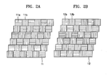
- FIGS. 2A and 2B illustrate first and second polarization grating screens 11 and 12 according to an exemplary embodiment of the present invention.
- each of the first polarization grating screen 11 and the second polarization grating screen 12 may be a combination of birefringence elements, that is, rotators and retarders. That is, the first polarization grating screen 11 realizes a 2D grating pattern with a plurality of first and second birefringence elements 11a and 11b, having a predetermined width, alternating with each other horizontally and vertically.
- the second polarization grating screen 12 realizes a 2D grating pattern with a plurality of third and fourth birefringence elements 12a and 12b, having a predetermined width, alternating with each other horizontally and vertically.
- the first and second birefringence elements and the third and fourth birefringence elements may be square.
- the grating patterns of the first and second polarization grating screens 11 and 12 are stepped grating patterns in which each row is shifted by a predetermined distance.
- the first and second birefringence elements 11a and 11b alternate with each other in a first row, that is, an uppermost row, of the first polarization grating screen 11.
- the second and first birefringence elements 11b and 11a alternate with each other in a second row, which is shifted slightly to the left from the first row.
- the first and second birefringence elements 11a and 11b alternate with each other in a third row, which is shifted slightly to the left from the second row.
- the grating patterns of the polarization grating screens 11 and 12 have a substantially stepped shape.
- the first and second birefringence elements 11a and 11b are rotators which are circular birefringence elements
- the first and second birefringence elements 11a and 11b rotate incident light by angles of +45° and -45°, respectively.
- the third and fourth birefringence elements 12a and 12b are rotators, they rotate incident light by angles of -45° and +45°, respectively.
- the first and second birefringence elements 11a and 11b may be retarders which are linear birefringence elements.
- the first and second birefringence elements 11a and 11b phase-delay incident light by + ⁇ /4 and - ⁇ /4, respectively.
- ⁇ denotes the wavelength of incident light.
- the third and fourth birefringence elements 12a and 12b are retarders, they phase-delay incident light by - ⁇ /4 and + ⁇ /4, respectively.
- incident polarized light of a predetermined direction is phase-delayed by + ⁇ /4 or - ⁇ /4, the direction of polarization of the incident light is changed by +45° or -45°.
- the first through fourth birefringence elements 11a, 11b, 12a, and 12b are rotators or retarders, they can uniquely change the directions of polarization of incident light.
- a 2D image or a 3D image can be realized by moving the first and second polarization grating screens 11 and 12 relative to each other.
- FIGS. 3A through 3C are schematic views for explaining a method of forming a 2D image using the first and second polarization grating screens 11 and 12 in a stereoscopic display according to an exemplary embodiment of the present invention.
- the first and second polarization grating screens 11 and 12 overlap each other such that the first and second birefringence elements 11a and 11b coincide with the corresponding third and fourth birefringence elements 12a and 12b.
- the first birefringence elements 11a is incident on the third birefringence elements 12a
- light transmitted through the second birefringence elements 11b is incident on the fourth birefringence elements 12b.
- the light transmitted through the first birefringence element 11a is rotated by +45° to have a polarization of 135°
- the light transmitted through the second birefringence element 11 b is rotated by -45° to have a polarization of 45°.
- the light transmitted through the first birefringence element 11a and incident on the third birefringence element 12a is rotated by -45 ° to have a polarization of 90°.
- the light transmitted through the second birefringence element 11b and incident on the fourth birefringence element 12b is rotated by +45° to have a polarization of 90° as well. Accordingly, when the first and second polarization grating screens 11 and 12 overlap each other as illustrated, light emitted from the second polarization grating screen 12 has a uniform polarization.
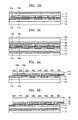
- FIG. 3B is a sectional view of the stereoscopic display of FIG. 3A configured to obtain a 2D image.
- the stereoscopic display includes a display device 10, which produces a predetermined image; a first polarization plate 13, which transmits only light with a predetermined direction of polarization; first and second polarization grating screens 11 and 12; and a second polarization plate 14, facing the second polarization grating screen 12, and which transmits only light with a predetermined direction of polarization of light transmitted through the second polarization grating screen 12.
- the first polarization plate 13, the first and second polarization grating screens 11 and 12, and the second polarization plate 14 constitute a parallax barrier unit that transmits all incident light in a 2D mode.
- the first and second polarization grating screens 11 and 12 overlap each other such that the first and second birefringence elements 11a and 11b of the first polarization grating screen coincide with the corresponding third and fourth birefringence elements 12a and 12b of the second polarization grating screen 12.
- the first polarization plate 13 may transmit only light with a polarization of 90° of light incident from the display device 10. After passing through the first polarization plate 13, part of the light passes through the first birefringence elements 11a and the third birefringence elements 12a, and the remaining part of the light passes through the second birefringence element 11bs and the fourth birefringence element 12bs. As described above, all light emitted from the second polarization grating screen 12 has the same polarization of 90°.
- the display device 10 displays a general 2D image, and the viewer can see the 2D image.
- the first and second birefringence elements 11a and 11b respectively rotate incident light by +45° and -45° and the third and fourth birefringence elements 12a and 12b respectively rotate incident light by -45° and +45°; however, the first through fourth birefringence elements 11a, 11b, 12a, and 12b may rotate incident light at different angles.
- the third and fourth birefringence elements 12a and 12b may respectively rotate incident light by +45° and -45°. In this case, if incident light with a polarization of 90° continuously passes through the first and third birefringence elements 11a and 12a, the transmitted light has a polarization of 180°.
- the transmitted light has a polarization of 0°. Therefore, if the first polarization plate 13 transmits only light with a polarization of 90°, the second polarization plate 14 should be able to transmit light with a polarization of 0° and 180°, perpendicular to the first polarization plate 13.
- the display device 10 may be any kind of display, for example, a PDP.
- the elements 11, 12, 13, and 14 constituting the parallax barrier unit are disposed between the display device 10 and a viewer.
- the display device 10 may be an LCD instead of the PDP.
- the LCD includes a backlight unit 15 (see FIG. 3C), which emits light; a rear polarization plate 16, which transmits only light with a predetermined direction of polarization of light emitted by the backlight unit 15; an LCD panel 17, which polarizes incident light for each pixel and provides an image; and a front polarization plate 18, which transmits only light with a predetermined direction of polarization of light transmitted through the LCD panel 17. Since the LCD includes rear and front polarization panels 16 and 18, the front polarization plate 18 of the LCD may be used as the first polarization plate of the parallax barrier unit when the parallax barrier unit is disposed between the viewer and the LCD. Additionally, as shown in FIG. 3C, the parallax barrier unit may be disposed between the backlight unit 15 and the LCD panel 17 of the LCD. In this case, the rear polarization plate 16 of the LCD may be used as the second polarization plate of the parallax barrier unit.
- FIGS. 4A and 4B are sectional views for explaining a method of forming a 3D image in the stereoscopic display according to an exemplary embodiment of the present invention.
- the first polarization grating screen 11 and the second polarization grating screen 12 of the parallax barrier unit are moved relative to one another by a predetermined distance in a horizontal direction. Either one or both of the first polarization grating screen 11 and the second polarization grating screen 12 can be moved.
- the first and second birefringence elements 11a and 11b of the first polarization grating screen 11 and the third and fourth birefringence elements 12a and 12b of the second polarization grating screen 12 are misaligned with each other.
- part of the light transmitted through the first birefringence elements 11a is transmitted through the third birefringence elements 12a, and the remaining part of the light transmitted through the first birefringence elements 11a is transmitted through the fourth birefringence elements 12b.
- Part of the light transmitted through the second birefringence elements 11b is transmitted through the third birefringence elements 12a, and the remaining part of the light is transmitted through the fourth birefringence elements 12b.
- the stereoscopic display operates as follows.
- first polarization plate 13 First, light emitted from the display device 10 is transmitted through the first polarization plate 13 to have a polarization of 90°. Thereafter, part of the light transmitted through the first polarization plate 13 is transmitted through the first birefringence elements 11a to have a polarization of 135°, and the remaining light transmitted through the first polarization plate 13 is transmitted through the second birefringence elements 11b to have a polarization of 45°. Part of the light transmitted through the first birefringence elements 11a is transmitted through the third birefringence elements 12a to have a polarization of 90°, and the remaining light transmitted through the first birefringence elements 11a is transmitted through the fourth birefringence elements 12b to have a polarization of 180°.
- part of the light transmitted through the second birefringence elements 11b is transmitted through the third birefringence elements 12a to have a polarization of 0°, and the remaining light transmitted through the second birefringence elements 11b is transmitted through the fourth birefringence elements 12b to have a polarization of 90°. Since the second polarization plate 14 transmits only light with a polarization of 90°, only the light continuously transmitted through the first birefringence elements 11a and the third birefringence elements 12a and the light continuously transmitted through the second birefringence elements 11b and the fourth birefringence elements 12b can be transmitted through the second polarization plate 14, and the other light is blocked off.
- the display device 10 includes a plurality of 2D pixels that emit light independently, and the display device 10 displays the images to be input to the left eye and to the right eye, respectively, in pixel areas corresponding to the transmission areas. Since binocular parallax occurs in this way, a stereoscopic 3D image can be obtained.
- FIG. 4C is a front view of a plurality of barriers and apertures formed by the black areas and the transmission areas.
- each of the polarization grating screens 11 and 12 has a stepped grating pattern.
- barriers 20 and apertures 21, formed by horizontally moving the two polarization grating screens 11 and 12 are inclined in a stepped pattern.
- Diagonally disposed corners of the apertures 21 for forming the left-eye image or the right-eye image are in contact with one another.
- a horizontal displacement between the two polarization grating screens 11 and 12 may be equal to a shift distance for rows of the grating patterns of the polarization grating screens 11 and 12.
- a plurality of apertures are vertically aligned to provide a 3D image, such that one aperture corresponds to one pixel of a display device. Accordingly, since the apertures for providing an image are densely aligned in the vertical direction, the resolution of the 3D image deteriorates, and color and brightness vary according to the viewer's position.
- one aperture of the 2D/3D switchable display according to the present invention corresponds to one of a red (R) sub-pixel, a green (G) sub-pixel, and a blue (B) sub-pixel of a display device, and three diagonally adjacent apertures form one pixel. That is, as shown in FIG. 4C, an aperture 21 R corresponds to a red (R) sub-pixel, an aperture 21 G corresponds to a green (G) sub-pixel, and an aperture 21B corresponds to a blue (B) sub-pixel.
- FIG. 4C an aperture 21 R corresponds to a red (R) sub-pixel
- an aperture 21 G corresponds to a green (G) sub-pixel
- an aperture 21B corresponds to a blue (B) sub-pixel.
- 4D is a front view of effective pixels of a 3D image formed by the stereoscopic display.
- red (R), green (G), and blue (B) sub-pixels are connected diagonally, and one pixel P is formed by three sub-pixels whose opposite diagonal corners are in contact.
- the shifted distance of the rows of the grating patterns of the polarization grating screens 11 and 12 may be equal to a width of one sub-pixel of the display device.
- the RGB sub-pixels are not densely arranged at a predetermined point, color and brightness vary little according to the viewer's position.
- the display device 10 may be a PDP or an LCD.
- a parallax barrier unit for generating parallax barriers is disposed between the backlight unit 15 and the LCD panel 17, as in FIG. 3C.
- the rear polarization plate 16 of the LCD may be used as the second polarization plate of the parallax barrier unit.
- the two exemplary polarization grating screens 11 and 12 described above move horizontally, they may move vertically. In this case, barriers and apertures are aligned in a horizontal direction and alternate in a vertical direction. Accordingly, the viewer can see a vertical stereoscopic image.
- the two polarization grating screens 11 and 12 move simultaneously a predetermined distance in both horizontal and vertical directions, vertical parallax as well as horizontal parallax is created, thereby providing a clearer stereoscopic image.
- a 2D/3D switchable display uses two polarization grating screens, thus enabling simple switching between a 2D mode and a 3D mode.
- the screens have stepped polarization grating patterns, when a 3D image is formed, a row of apertures is inclined diagonally, and three diagonally adjacent apertures form one pixel. Therefore, color and brightness vary little according to the viewer's position, in comparison to the conventional art. As a result, a multi-viewpoint image can be obtained.
- the 2D/3D switchable stereoscopic display of preferred embodiments of the present invention can provide a clearer stereoscopic image than a conventional 2D/3D switchable stereoscopic display.
Landscapes
- Engineering & Computer Science (AREA)
- Multimedia (AREA)
- Signal Processing (AREA)
- Stereoscopic And Panoramic Photography (AREA)
- Testing, Inspecting, Measuring Of Stereoscopic Televisions And Televisions (AREA)
Applications Claiming Priority (1)
| Application Number | Priority Date | Filing Date | Title |
|---|---|---|---|
| KR1020050028077A KR101086412B1 (ko) | 2005-04-04 | 2005-04-04 | 편광격자 스크린을 이용한 2차원/3차원 영상 호환용 입체영상 디스플레이 장치 |
Publications (3)
| Publication Number | Publication Date |
|---|---|
| EP1711022A2 true EP1711022A2 (fr) | 2006-10-11 |
| EP1711022A3 EP1711022A3 (fr) | 2010-01-20 |
| EP1711022B1 EP1711022B1 (fr) | 2011-03-09 |
Family
ID=36699336
Family Applications (1)
| Application Number | Title | Priority Date | Filing Date |
|---|---|---|---|
| EP06251660A Expired - Lifetime EP1711022B1 (fr) | 2005-04-04 | 2006-03-28 | Dispositif d'affichage stéréoscopique avec commutation entre des modes de fonctionnement 3D et 2D en utilisant une grille de diffraction de polarisation |
Country Status (6)
| Country | Link |
|---|---|
| US (1) | US7697203B2 (fr) |
| EP (1) | EP1711022B1 (fr) |
| JP (1) | JP4925702B2 (fr) |
| KR (1) | KR101086412B1 (fr) |
| CN (1) | CN100378507C (fr) |
| DE (1) | DE602006020519D1 (fr) |
Cited By (5)
| Publication number | Priority date | Publication date | Assignee | Title |
|---|---|---|---|---|
| EP1950980A1 (fr) * | 2007-01-24 | 2008-07-30 | Samsung Electronics Co., Ltd. | Appareil d'affichage autostéreoscopique commutable en 2D/3D et hautement efficace, utilisant un écran gaufré et un multiplexage temporel des vues 3D |
| EP1965245A1 (fr) * | 2007-02-27 | 2008-09-03 | Samsung Electronics Co., Ltd. | Appareil d'affichage stéréoscopique |
| CN102081238A (zh) * | 2010-12-17 | 2011-06-01 | 电子科技大学 | 一种光控的光栅式自由立体显示器件及其制备方法 |
| EP2772784A4 (fr) * | 2011-10-27 | 2015-05-27 | Neoviewkolon Co Ltd | Dispositif d'affichage transparent d'images stéréoscopiques |
| CN108732749A (zh) * | 2017-04-13 | 2018-11-02 | 印正有限公司 | 显示装置 |
Families Citing this family (56)
| Publication number | Priority date | Publication date | Assignee | Title |
|---|---|---|---|---|
| KR101086412B1 (ko) | 2005-04-04 | 2011-11-25 | 삼성전자주식회사 | 편광격자 스크린을 이용한 2차원/3차원 영상 호환용 입체영상 디스플레이 장치 |
| KR101086411B1 (ko) * | 2005-04-04 | 2011-11-25 | 삼성전자주식회사 | 2차원/3차원 영상 호환용 입체 영상 디스플레이 장치 |
| KR20070006116A (ko) * | 2005-07-07 | 2007-01-11 | 삼성전자주식회사 | 2차원/3차원 영상 호환용 완전시차 입체 영상 디스플레이장치 |
| KR20070094170A (ko) * | 2006-03-16 | 2007-09-20 | 엘지전자 주식회사 | 플라즈마 디스플레이 패널의 입체영상 구현장치 |
| KR100839414B1 (ko) * | 2007-04-19 | 2008-06-19 | 삼성에스디아이 주식회사 | 전자 영상 기기 |
| CN101131501B (zh) * | 2007-09-20 | 2012-07-04 | 友达光电股份有限公司 | 显示装置、形成显示装置的方法及呈现立体影像的方法 |
| KR20100033067A (ko) | 2008-09-19 | 2010-03-29 | 삼성전자주식회사 | 2차원과 3차원 겸용 영상 표시 장치 및 방법 |
| CN101494800B (zh) * | 2009-02-27 | 2012-04-04 | 福建华映显示科技有限公司 | 影像处理方法及影像处理装置 |
| TWI419124B (zh) * | 2009-03-06 | 2013-12-11 | Au Optronics Corp | 二維/三維影像顯示裝置 |
| IL201110A (en) * | 2009-09-22 | 2014-08-31 | Vorotec Ltd | Apparatus and method for navigation |
| KR101256936B1 (ko) * | 2009-12-11 | 2013-04-25 | 삼성메디슨 주식회사 | 초음파 진단 시스템 |
| EP2355526A3 (fr) | 2010-01-14 | 2012-10-31 | Nintendo Co., Ltd. | Support de stockage lisible sur ordinateur doté d'un programme de contrôle de l'affichage stocké dessus, appareil de contrôle de l'affichage, système de contrôle de l'affichage et procédé de contrôle de l'affichage |
| EP2539853B1 (fr) | 2010-02-25 | 2019-01-09 | Lirhot Systems Ltd. | Filtre de lumière avec angles de polarisation variables et algorithme de traitement |
| KR20110113457A (ko) * | 2010-04-09 | 2011-10-17 | 차형경 | 나안방식 대형 3d 디스플레이 기술 |
| TWI417866B (zh) * | 2010-04-22 | 2013-12-01 | Chunghwa Picture Tubes Ltd | 立體畫面顯示方法及其立體顯示裝置 |
| US20130057663A1 (en) * | 2010-04-30 | 2013-03-07 | Alexandre M. Bratkovski | Image viewing systems with dynamically reconfigurable screens for three-dimensional viewing |
| JP5872185B2 (ja) * | 2010-05-27 | 2016-03-01 | 任天堂株式会社 | 携帯型電子機器 |
| US9693039B2 (en) | 2010-05-27 | 2017-06-27 | Nintendo Co., Ltd. | Hand-held electronic device |
| KR101753801B1 (ko) * | 2010-06-10 | 2017-07-04 | 엘지디스플레이 주식회사 | 액정 표시장치 및 구동방법 |
| TWI439730B (zh) * | 2010-07-16 | 2014-06-01 | Au Optronics Corp | 視差控制元件及其應用 |
| KR101174076B1 (ko) * | 2010-08-31 | 2012-08-16 | 유한회사 마스터이미지쓰리디아시아 | 사선 방향 패럴랙스 베리어 방식 입체영상 표시 장치 |
| CN102096228B (zh) * | 2010-12-17 | 2012-07-04 | 湖南创图视维科技有限公司 | 一种显示系统和显示方法 |
| KR101239230B1 (ko) * | 2010-12-17 | 2013-03-06 | 한국과학기술연구원 | 입체영상 표시장치 및 그 구동 방법 |
| CN102541329B (zh) * | 2010-12-27 | 2016-01-20 | 上海天马微电子有限公司 | 触控式面板以及包括该面板的显示装置 |
| JP5608569B2 (ja) * | 2011-01-05 | 2014-10-15 | Necパーソナルコンピュータ株式会社 | ディスプレイ装置、情報処理装置及び表示制御方法 |
| TW201232039A (en) * | 2011-01-28 | 2012-08-01 | Chunghwa Picture Tubes Ltd | Stereoscopic display device with changeable barrier patterns |
| US8587751B2 (en) | 2011-02-14 | 2013-11-19 | Samsung Electronics Co., Ltd. | Display panel and display apparatus having the same |
| EP2487530B1 (fr) | 2011-02-14 | 2015-02-25 | Samsung Electronics Co., Ltd. | Panneau d'affichage comprenant un polariseur sélectif de couleur type à grille métallique |
| US8964012B2 (en) * | 2011-02-14 | 2015-02-24 | Samsung Electronics Co., Ltd. | Display panel having a polarizing layer and display apparatus having the same |
| JP2013019924A (ja) * | 2011-06-17 | 2013-01-31 | Sony Corp | 偏光モジュール及び画像表示装置 |
| US9432658B2 (en) * | 2011-06-20 | 2016-08-30 | Panasonic Intellectual Property Corporation Of America | Image display device |
| TW201307897A (zh) * | 2011-08-04 | 2013-02-16 | Benq Materials Corp | 立體效果顯示面板及其相位差膜 |
| US9338445B2 (en) | 2011-08-04 | 2016-05-10 | Dolby Laboratories Licensing Corporation | Method and apparatus for full resolution 3D display |
| KR101472180B1 (ko) | 2011-08-09 | 2014-12-15 | 주식회사 엘지화학 | 광학 필터 |
| WO2013022258A2 (fr) * | 2011-08-09 | 2013-02-14 | 주식회사 엘지화학 | Filtre optique |
| KR101841619B1 (ko) * | 2011-11-14 | 2018-03-26 | 삼성디스플레이 주식회사 | 금속선 격자 편광소자를 포함하는 액정 표시 장치 및 그 제조 방법 |
| US20130176407A1 (en) * | 2012-01-05 | 2013-07-11 | Reald Inc. | Beam scanned display apparatus and method thereof |
| JP5583158B2 (ja) * | 2012-02-29 | 2014-09-03 | 株式会社東芝 | 液晶光学素子、駆動装置及び画像表示装置 |
| US9071833B1 (en) | 2012-07-10 | 2015-06-30 | Sprint Communications Company L.P. | Two-dimensional supplementary information in a three-dimensional image |
| KR20140011574A (ko) | 2012-07-17 | 2014-01-29 | 삼성디스플레이 주식회사 | 표시 장치 및 그 구동 방법 |
| CN103018940B (zh) * | 2012-12-14 | 2015-04-22 | 京东方科技集团股份有限公司 | 3d显示控制方法、控制装置及显示设备 |
| CN103246071B (zh) * | 2013-04-28 | 2015-10-14 | 京东方科技集团股份有限公司 | 一种3d显示装置 |
| US9551878B2 (en) * | 2013-12-17 | 2017-01-24 | Shenzhen China Star Optoelectronics Technology Co., Ltd | Patterned retarder film and display apparatus |
| US10409079B2 (en) | 2014-01-06 | 2019-09-10 | Avegant Corp. | Apparatus, system, and method for displaying an image using a plate |
| US10303242B2 (en) | 2014-01-06 | 2019-05-28 | Avegant Corp. | Media chair apparatus, system, and method |
| KR101594521B1 (ko) * | 2014-05-30 | 2016-02-26 | 주식회사 레드로버 | 패럴랙스 베리어 및 이를 포함하는 입체영상 디스플레이장치 |
| CN104020573B (zh) * | 2014-06-04 | 2016-03-23 | 四川大学 | 一种基于正交偏振方向性背光源的多视点3d显示装置 |
| CN104656304B (zh) * | 2015-02-13 | 2018-05-01 | 厦门天马微电子有限公司 | 一种显示面板的制作方法 |
| US9823474B2 (en) | 2015-04-02 | 2017-11-21 | Avegant Corp. | System, apparatus, and method for displaying an image with a wider field of view |
| US9995857B2 (en) | 2015-04-03 | 2018-06-12 | Avegant Corp. | System, apparatus, and method for displaying an image using focal modulation |
| CN110113596B (zh) * | 2018-02-01 | 2021-04-27 | 上海济丽信息技术有限公司 | 一种可切换光栅式裸眼3d显示系统及显示方法 |
| CN108663818B (zh) * | 2018-08-13 | 2023-11-14 | 成都航空职业技术学院 | 一种自由立体双视显示装置及方法 |
| CN109298536B (zh) * | 2018-11-20 | 2023-09-12 | 成都航空职业技术学院 | 一种一维双视3d显示装置 |
| CN113711111B (zh) * | 2019-04-15 | 2023-10-17 | 镭亚股份有限公司 | 具有对角视差的静态多视图显示器和方法 |
| CN112014971B (zh) * | 2019-05-31 | 2025-05-16 | 杭州光粒科技有限公司 | 增强现实显示组件及具有该组件的增强现实显示设备 |
| CN113805351B (zh) * | 2021-10-26 | 2024-09-13 | Oppo广东移动通信有限公司 | 显示屏、电子设备以及3d成像系统 |
Citations (2)
| Publication number | Priority date | Publication date | Assignee | Title |
|---|---|---|---|---|
| US20040109115A1 (en) | 2002-12-05 | 2004-06-10 | Chao-Hsu Tsai | Display device for automatically switching between 2D and 3D images |
| EP1666950A2 (fr) | 2004-11-29 | 2006-06-07 | Samsung Electronics Co, Ltd | Barrière à parallaxe pour un afficheur autostereoscopique |
Family Cites Families (22)
| Publication number | Priority date | Publication date | Assignee | Title |
|---|---|---|---|---|
| US5113285A (en) * | 1990-09-28 | 1992-05-12 | Honeywell Inc. | Full color three-dimensional flat panel display |
| US5264964A (en) * | 1991-12-18 | 1993-11-23 | Sades Faris | Multi-mode stereoscopic imaging system |
| JPH08240790A (ja) * | 1994-12-16 | 1996-09-17 | Sharp Corp | 自動立体表示装置および空間光変調器 |
| JP2778543B2 (ja) * | 1995-07-27 | 1998-07-23 | 日本電気株式会社 | 立体表示装置 |
| JPH09113862A (ja) * | 1995-10-24 | 1997-05-02 | Mitsubishi Electric Corp | 立体映像表示装置 |
| US6046849A (en) * | 1996-09-12 | 2000-04-04 | Sharp Kabushiki Kaisha | Parallax barrier, display, passive polarisation modulating optical element and method of making such an element |
| JP2882393B2 (ja) * | 1997-01-27 | 1999-04-12 | 日本電気株式会社 | 立体表示装置 |
| JPH11285031A (ja) | 1998-03-26 | 1999-10-15 | Mr System Kenkyusho:Kk | 立体画像表示装置 |
| KR100625028B1 (ko) | 1999-05-28 | 2006-09-20 | 엘지.필립스 엘시디 주식회사 | 멀티모드용 입체화상 표시장치 |
| JP2002296540A (ja) | 2001-03-29 | 2002-10-09 | Sanyo Electric Co Ltd | 眼鏡無し立体映像表示装置 |
| KR100783358B1 (ko) | 2001-04-27 | 2007-12-07 | 엘지.필립스 엘시디 주식회사 | 입체영상 표시장치 및 제조방법 |
| JP2003202517A (ja) | 2001-12-28 | 2003-07-18 | Canon Inc | 立体画像表示装置 |
| JP2003337390A (ja) * | 2002-05-17 | 2003-11-28 | Canon Inc | 画像表示装置および画像表示システム |
| GB2390172A (en) * | 2002-06-28 | 2003-12-31 | Sharp Kk | Polarising optical element and display |
| JP4088878B2 (ja) * | 2002-09-06 | 2008-05-21 | ソニー株式会社 | 立体画像表示装置 |
| KR100785982B1 (ko) * | 2002-11-07 | 2007-12-14 | 산요덴키가부시키가이샤 | 입체 영상 처리 방법 및 입체 영상 표시 장치 |
| CN1243272C (zh) * | 2002-12-10 | 2006-02-22 | 财团法人工业技术研究院 | 2d-3d切换式自动立体显示装置 |
| JP4098612B2 (ja) * | 2002-12-10 | 2008-06-11 | 株式会社東芝 | 三次元画像表示装置 |
| KR100580633B1 (ko) * | 2003-12-10 | 2006-05-16 | 삼성전자주식회사 | 디스플레이 디바이스 |
| KR101086412B1 (ko) | 2005-04-04 | 2011-11-25 | 삼성전자주식회사 | 편광격자 스크린을 이용한 2차원/3차원 영상 호환용 입체영상 디스플레이 장치 |
| KR101086411B1 (ko) * | 2005-04-04 | 2011-11-25 | 삼성전자주식회사 | 2차원/3차원 영상 호환용 입체 영상 디스플레이 장치 |
| KR20070006116A (ko) * | 2005-07-07 | 2007-01-11 | 삼성전자주식회사 | 2차원/3차원 영상 호환용 완전시차 입체 영상 디스플레이장치 |
-
2005
- 2005-04-04 KR KR1020050028077A patent/KR101086412B1/ko not_active Expired - Fee Related
-
2006
- 2006-03-21 CN CNB2006100660172A patent/CN100378507C/zh not_active Expired - Fee Related
- 2006-03-28 DE DE602006020519T patent/DE602006020519D1/de not_active Expired - Lifetime
- 2006-03-28 EP EP06251660A patent/EP1711022B1/fr not_active Expired - Lifetime
- 2006-03-29 JP JP2006091933A patent/JP4925702B2/ja not_active Expired - Fee Related
- 2006-04-04 US US11/396,559 patent/US7697203B2/en not_active Expired - Fee Related
Patent Citations (2)
| Publication number | Priority date | Publication date | Assignee | Title |
|---|---|---|---|---|
| US20040109115A1 (en) | 2002-12-05 | 2004-06-10 | Chao-Hsu Tsai | Display device for automatically switching between 2D and 3D images |
| EP1666950A2 (fr) | 2004-11-29 | 2006-06-07 | Samsung Electronics Co, Ltd | Barrière à parallaxe pour un afficheur autostereoscopique |
Cited By (6)
| Publication number | Priority date | Publication date | Assignee | Title |
|---|---|---|---|---|
| EP1950980A1 (fr) * | 2007-01-24 | 2008-07-30 | Samsung Electronics Co., Ltd. | Appareil d'affichage autostéreoscopique commutable en 2D/3D et hautement efficace, utilisant un écran gaufré et un multiplexage temporel des vues 3D |
| US7522340B2 (en) | 2007-01-24 | 2009-04-21 | Samsung Electronics Co., Ltd. | Highly efficient 2D/3D switchable display apparatus |
| EP1965245A1 (fr) * | 2007-02-27 | 2008-09-03 | Samsung Electronics Co., Ltd. | Appareil d'affichage stéréoscopique |
| CN102081238A (zh) * | 2010-12-17 | 2011-06-01 | 电子科技大学 | 一种光控的光栅式自由立体显示器件及其制备方法 |
| EP2772784A4 (fr) * | 2011-10-27 | 2015-05-27 | Neoviewkolon Co Ltd | Dispositif d'affichage transparent d'images stéréoscopiques |
| CN108732749A (zh) * | 2017-04-13 | 2018-11-02 | 印正有限公司 | 显示装置 |
Also Published As
| Publication number | Publication date |
|---|---|
| US20060227420A1 (en) | 2006-10-12 |
| EP1711022B1 (fr) | 2011-03-09 |
| CN1847927A (zh) | 2006-10-18 |
| JP4925702B2 (ja) | 2012-05-09 |
| EP1711022A3 (fr) | 2010-01-20 |
| KR101086412B1 (ko) | 2011-11-25 |
| DE602006020519D1 (de) | 2011-04-21 |
| JP2006285247A (ja) | 2006-10-19 |
| CN100378507C (zh) | 2008-04-02 |
| US7697203B2 (en) | 2010-04-13 |
| KR20060105351A (ko) | 2006-10-11 |
Similar Documents
| Publication | Publication Date | Title |
|---|---|---|
| EP1711022B1 (fr) | Dispositif d'affichage stéréoscopique avec commutation entre des modes de fonctionnement 3D et 2D en utilisant une grille de diffraction de polarisation | |
| US7468838B2 (en) | Stereoscopic display for switching between 2D/3D images | |
| CN1893674B (zh) | 提供全视差图像的2d/3d可转换立体显示器 | |
| KR100728777B1 (ko) | 패럴랙스 베리어 및 이를 구비한 입체 영상 표시장치 | |
| CN101093630B (zh) | 三维图像显示装置 | |
| TWI407772B (zh) | 自動立體顯示裝置及其濾色器 | |
| KR100759393B1 (ko) | 패럴랙스 배리어 및 이를 구비한 입체 영상 표시장치 | |
| JP4400172B2 (ja) | 画像表示装置、携帯端末装置、表示パネル及び画像表示方法 | |
| KR101001627B1 (ko) | 입체 영상표시장치 | |
| EP1965245A1 (fr) | Appareil d'affichage stéréoscopique | |
| JP4602960B2 (ja) | 3次元映像表示装置用表示パネル及びこれを備える3次元映像表示装置 | |
| KR20070001528A (ko) | 렌티큘러방식 입체영상표시장치 | |
| KR20140070789A (ko) | 입체 영상 표시 장치 및 그 구동 방법 | |
| KR100852758B1 (ko) | 영상 디스플레이 장치 | |
| US8427591B2 (en) | 3D liquid crystal display system | |
| Tsai et al. | 32.4: Invited Paper: The Pursuit of High‐Definition 3D Display Technology | |
| KR102059469B1 (ko) | 입체 표시 장치 | |
| KR20140055532A (ko) | 3차원 영상 표시장치의 구동방법 | |
| KR100745460B1 (ko) | 입체영상구현용 액정표시장치 | |
| JP2012123129A (ja) | 立体画像表示装置 |
Legal Events
| Date | Code | Title | Description |
|---|---|---|---|
| PUAI | Public reference made under article 153(3) epc to a published international application that has entered the european phase |
Free format text: ORIGINAL CODE: 0009012 |
|
| 17P | Request for examination filed |
Effective date: 20060328 |
|
| AK | Designated contracting states |
Kind code of ref document: A2 Designated state(s): AT BE BG CH CY CZ DE DK EE ES FI FR GB GR HU IE IS IT LI LT LU LV MC NL PL PT RO SE SI SK TR |
|
| AX | Request for extension of the european patent |
Extension state: AL BA HR MK YU |
|
| PUAL | Search report despatched |
Free format text: ORIGINAL CODE: 0009013 |
|
| AK | Designated contracting states |
Kind code of ref document: A3 Designated state(s): AT BE BG CH CY CZ DE DK EE ES FI FR GB GR HU IE IS IT LI LT LU LV MC NL PL PT RO SE SI SK TR |
|
| AX | Request for extension of the european patent |
Extension state: AL BA HR MK YU |
|
| 17Q | First examination report despatched |
Effective date: 20100308 |
|
| RIC1 | Information provided on ipc code assigned before grant |
Ipc: H04N 13/00 20060101AFI20100721BHEP |
|
| AKX | Designation fees paid |
Designated state(s): DE FR GB IT NL |
|
| GRAP | Despatch of communication of intention to grant a patent |
Free format text: ORIGINAL CODE: EPIDOSNIGR1 |
|
| GRAS | Grant fee paid |
Free format text: ORIGINAL CODE: EPIDOSNIGR3 |
|
| GRAA | (expected) grant |
Free format text: ORIGINAL CODE: 0009210 |
|
| AK | Designated contracting states |
Kind code of ref document: B1 Designated state(s): DE FR GB IT NL |
|
| REG | Reference to a national code |
Ref country code: GB Ref legal event code: FG4D |
|
| REF | Corresponds to: |
Ref document number: 602006020519 Country of ref document: DE Date of ref document: 20110421 Kind code of ref document: P |
|
| REG | Reference to a national code |
Ref country code: DE Ref legal event code: R096 Ref document number: 602006020519 Country of ref document: DE Effective date: 20110421 |
|
| REG | Reference to a national code |
Ref country code: NL Ref legal event code: T3 |
|
| PLBE | No opposition filed within time limit |
Free format text: ORIGINAL CODE: 0009261 |
|
| STAA | Information on the status of an ep patent application or granted ep patent |
Free format text: STATUS: NO OPPOSITION FILED WITHIN TIME LIMIT |
|
| 26N | No opposition filed |
Effective date: 20111212 |
|
| REG | Reference to a national code |
Ref country code: DE Ref legal event code: R097 Ref document number: 602006020519 Country of ref document: DE Effective date: 20111212 |
|
| PG25 | Lapsed in a contracting state [announced via postgrant information from national office to epo] |
Ref country code: IT Free format text: LAPSE BECAUSE OF FAILURE TO SUBMIT A TRANSLATION OF THE DESCRIPTION OR TO PAY THE FEE WITHIN THE PRESCRIBED TIME-LIMIT Effective date: 20110309 |
|
| REG | Reference to a national code |
Ref country code: FR Ref legal event code: PLFP Year of fee payment: 11 |
|
| REG | Reference to a national code |
Ref country code: FR Ref legal event code: PLFP Year of fee payment: 12 |
|
| REG | Reference to a national code |
Ref country code: FR Ref legal event code: PLFP Year of fee payment: 13 |
|
| PGFP | Annual fee paid to national office [announced via postgrant information from national office to epo] |
Ref country code: NL Payment date: 20190221 Year of fee payment: 14 |
|
| PGFP | Annual fee paid to national office [announced via postgrant information from national office to epo] |
Ref country code: FR Payment date: 20190225 Year of fee payment: 14 |
|
| PGFP | Annual fee paid to national office [announced via postgrant information from national office to epo] |
Ref country code: DE Payment date: 20200220 Year of fee payment: 15 Ref country code: GB Payment date: 20200225 Year of fee payment: 15 |
|
| REG | Reference to a national code |
Ref country code: NL Ref legal event code: MM Effective date: 20200401 |
|
| PG25 | Lapsed in a contracting state [announced via postgrant information from national office to epo] |
Ref country code: NL Free format text: LAPSE BECAUSE OF NON-PAYMENT OF DUE FEES Effective date: 20200401 |
|
| PG25 | Lapsed in a contracting state [announced via postgrant information from national office to epo] |
Ref country code: FR Free format text: LAPSE BECAUSE OF NON-PAYMENT OF DUE FEES Effective date: 20200331 |
|
| REG | Reference to a national code |
Ref country code: DE Ref legal event code: R119 Ref document number: 602006020519 Country of ref document: DE |
|
| GBPC | Gb: european patent ceased through non-payment of renewal fee |
Effective date: 20210328 |
|
| PG25 | Lapsed in a contracting state [announced via postgrant information from national office to epo] |
Ref country code: GB Free format text: LAPSE BECAUSE OF NON-PAYMENT OF DUE FEES Effective date: 20210328 Ref country code: DE Free format text: LAPSE BECAUSE OF NON-PAYMENT OF DUE FEES Effective date: 20211001 |