EP1711032A2 - Akustische Schwingplatte - Google Patents
Akustische Schwingplatte Download PDFInfo
- Publication number
- EP1711032A2 EP1711032A2 EP06006921A EP06006921A EP1711032A2 EP 1711032 A2 EP1711032 A2 EP 1711032A2 EP 06006921 A EP06006921 A EP 06006921A EP 06006921 A EP06006921 A EP 06006921A EP 1711032 A2 EP1711032 A2 EP 1711032A2
- Authority
- EP
- European Patent Office
- Prior art keywords
- vibratory plate
- acoustic vibratory
- polymer material
- laminated bodies
- acoustic
- Prior art date
- Legal status (The legal status is an assumption and is not a legal conclusion. Google has not performed a legal analysis and makes no representation as to the accuracy of the status listed.)
- Withdrawn
Links
Images



Classifications
-
- H—ELECTRICITY
- H04—ELECTRIC COMMUNICATION TECHNIQUE
- H04R—LOUDSPEAKERS, MICROPHONES, GRAMOPHONE PICK-UPS OR LIKE ACOUSTIC ELECTROMECHANICAL TRANSDUCERS; ELECTRIC HEARING AIDS; PUBLIC ADDRESS SYSTEMS
- H04R7/00—Diaphragms for electromechanical transducers; Cones
- H04R7/02—Diaphragms for electromechanical transducers; Cones characterised by the construction
- H04R7/04—Plane diaphragms
- H04R7/06—Plane diaphragms comprising a plurality of sections or layers
- H04R7/10—Plane diaphragms comprising a plurality of sections or layers comprising superposed layers in contact
-
- H—ELECTRICITY
- H04—ELECTRIC COMMUNICATION TECHNIQUE
- H04R—LOUDSPEAKERS, MICROPHONES, GRAMOPHONE PICK-UPS OR LIKE ACOUSTIC ELECTROMECHANICAL TRANSDUCERS; ELECTRIC HEARING AIDS; PUBLIC ADDRESS SYSTEMS
- H04R7/00—Diaphragms for electromechanical transducers; Cones
- H04R7/02—Diaphragms for electromechanical transducers; Cones characterised by the construction
- H04R7/04—Plane diaphragms
- H04R7/06—Plane diaphragms comprising a plurality of sections or layers
-
- H—ELECTRICITY
- H04—ELECTRIC COMMUNICATION TECHNIQUE
- H04R—LOUDSPEAKERS, MICROPHONES, GRAMOPHONE PICK-UPS OR LIKE ACOUSTIC ELECTROMECHANICAL TRANSDUCERS; ELECTRIC HEARING AIDS; PUBLIC ADDRESS SYSTEMS
- H04R2307/00—Details of diaphragms or cones for electromechanical transducers, their suspension or their manufacture covered by H04R7/00 or H04R31/003, not provided for in any of its subgroups
- H04R2307/029—Diaphragms comprising fibres
-
- H—ELECTRICITY
- H04—ELECTRIC COMMUNICATION TECHNIQUE
- H04R—LOUDSPEAKERS, MICROPHONES, GRAMOPHONE PICK-UPS OR LIKE ACOUSTIC ELECTROMECHANICAL TRANSDUCERS; ELECTRIC HEARING AIDS; PUBLIC ADDRESS SYSTEMS
- H04R31/00—Apparatus or processes specially adapted for the manufacture of transducers or diaphragms therefor
Definitions
- the present invention relates to an acoustic vibratory plate used in a speaker or the like.
- the elastic modulus influences a piston vibration band B1 and the internal loss influences peak-dip of a split vibration band B2. Furthermore, for flattening, a high internal loss, that is, high damping property is required.
- the piston band B1 is enlarged in a direction X1 in which the frequency becomes larger. Furthermore, by increasing the internal loss, a resonance peak P is reduced in a direction X2 in which a sound pressure becomes lower. In addition, by increasing the damping property, that is, by making the internal loss higher, a curve profile indicating the frequency response becomes smoother, so that the flattening is improved.
- the density influences a reproduction sound pressure level. More specifically, by making the density lower, in other words, by making the material more light-weighted, sensitivity (level) is improved in a direction X3 in which the sound pressure becomes higher.
- a damping material with a high internal loss such as a damping agent has been applied to a surface of the vibratory plate, by which peak-dip of the split vibration is flattened.
- an acoustic vibratory plate is an acoustic vibratory plate having at least first to third laminated bodies layered.
- the first and third laminated bodies are formed of a polymer material
- the second laminated body is formed of a polymer material different from the polymer material forming the first and third laminated bodies in dynamic internal loss.
- an acoustic vibratory plate is an acoustic vibratory plate having three or more multiple-laminated bodies layered.
- each of the laminated bodies is formed of a first or second polymer material different from each other in dynamic internal loss, and the laminated body formed of the first polymer material and the laminated body formed of the second polymer material are arranged alternately.
- the acoustic vibratory plate according to the embodiments of the present invention effectively increases the internal loss and realizes an increase in damping property, thereby realizing the flattening of peak-dip of a split region.
- Fig. 1A and Fig. 1B show an acoustic vibratory plate to which the present invention is applied: Fig. 1A is a cross-sectional view in normal times and Fig. 1B is a cross-sectional view showing damping by shear deformation during vibration.
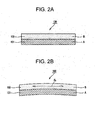
- Fig. 2A and Fig. 2B show a related art acoustic vibratory plate: Fig. 2A is a cross-sectional view in normal times and Fig. 2B is a cross-sectional view showing damping by stretching deformation of a damping agent during vibration.
- Fig. 3 is a characteristic chart showing relationships between a reproduction frequency response of an acoustic vibratory plate according to Example 3 and reproduction frequency responses of acoustic vibratory plates of Comparative Examples 3-1, 3-2.
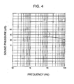
- Fig. 4 is a characteristic chart showing a reproduction frequency response of an acoustic vibratory plate according to Example 4.
- Fig. 5 is a characteristic chart showing a relationship between a reproduction frequency response of an acoustic vibratory plate according to Example 5 and a reproduction frequency response of an acoustic vibratory plate of Comparative Example 5.
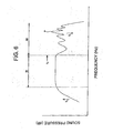
- Fig. 6 is a chart showing relationships of a reproduction frequency response of a related art acoustic vibratory plate.
- a first laminated body 11 a second laminated body 12 and a third laminated body 13 are layered in order in a thickness direction.
- the first laminated body 11 and the third laminated body 13 are made of a polymer material A. Although the first and third laminated bodies 11 and 13 are made of the same material in the present embodiment, they may be made of different materials.
- polyester PET
- PC polycarbonate
- PEN polyethylene naphthalate
- PEEK polyether ether keton
- PP polypropylene
- TPX polymethylpentene
- the polymer material A containing a polymer alone may be a colored one such as polyimide (PI), polyether imide (PEI), liquid crystal polymer (LCP) or the like.
- PI polyimide
- PEI polyether imide
- LCP liquid crystal polymer
- the second laminated body 12 is formed between the first and third laminated bodies 11, 13, and is made of a damping agent B which is a polymer material with a high damping property.
- the second laminated body 12 is made of the damping agent B which is a material with a higher dynamic internal loss than that of the polymer material A forming the first and third laminated bodies 11, 13.
- this damping agent B a hot-melt, polyester-based adhesive for laminate containing a polyester resin (vylon-300 produced by TOYOBO., LTD) as a main component, a hot-melt film adhesive (Admer film (olefin-based resin) (TOHCELLO CO., LTD) hot-melt film) or the like is used.
- the first to third laminated bodies 11, 12, 13 are layered in the thickness direction, the first and third laminated bodies 11, 13 are formed of the polymer material A, and the second laminated body 12 is formed of the damping agent B, that is, the polymer material with a higher dynamic internal loss than that of the polymer material A.
- This structure effectively increases the internal loss in the entire three-layered structure and realizes an increase in damping property, thereby realizing the flattening of peak-dip in a split region.
- the present invention is not limited to this.
- any acoustic vibratory plate that is made of a multilayer film having a multilayer structure formed by layering three or more multiple-laminated bodies.
- film materials such as the polymer material A and the damping agent B are layered in such a manner that the adjacent laminated bodies have different properties, that is, different dynamic internal losses.
- an acoustic vibratory plate may have a four-layered structure formed by layering the materials in the order of A/B/A/B, may have a five-layered structure formed by layering the materials in the order of A/B/A/B/A, and may have a further multilayer structure.
- the multilayer structure is obtained by increasing the laminated bodies in number, for example, by layering three or more multiple-laminated bodies, forming each of the laminated bodies by the first polymer material A or the damping agent B as the second polymer material which have different dynamic internal losses from each other, and arranging the laminated body formed of the first polymer material A and the laminated body formed of the second polymer material B alternately.
- the internal loss can be increased because of an effect of shear deformation described later, so that the damping property can be enhanced to the extent of the increased laminated bodies.
- a damping mechanism of the acoustic vibratory plate 1 to which the present invention is applied is now described in comparison with a damping mechanism of a related art acoustic vibratory plate by considering respective bending vibrations.
- a description of the respective damping mechanisms is given in comparison by considering the bending vibrations in reference to Figs. 1 and 2, in which a polymer material is denoted by A and a damping agent which is a polymer material with a dynamic internal loss different from that of the polymer material A is denoted by B, which compose the acoustic vibratory plate 1 to which the present invention is applied and an acoustic vibratory plate 100 as an comparative example for comparing with the acoustic vibratory plate 1.
- the bending vibration is a kind of stretching deformation of the materials and that the magnitude of the damping property depends on the internal losses of the materials and the structure by which the material are composed. Namely, if the acoustic vibratory plate is made of only a material with a high internal loss, the damping property is high. On the other hand, in the case where the laminated bodies made of the polymer material A and the damping agent B which are different kinds of materials are layered as in the acoustic vibratory plate 1 of the embodiment of the present invention, this layered structure largely influences the damping property.
- acoustic vibratory plate 100 according to the comparative example for comparing with the acoustic vibratory plate 1 to which the present invention is applied, which has a three-layered structure as shown in Fig. 1A, is described in reference to Fig. 2.
- the acoustic vibratory plate 100 of the comparative example has a two-layered structure in which a first laminated body 101 made of the polymer material A and a second laminated body 102 made of the damping agent B are layered in the thickness direction.
- the damping agent B is applied to the first laminated body 101 to thereby make up the acoustic vibratory plate 100.
- the acoustic vibratory plate 100 has the two-layered structure as shown in Fig. 2A, and the damping mechanism of this two-layered structure is implemented by energy absorption by stretching deformation of the damping agent B with a high internal loss. More specifically, as shown in Fig. 2B, the energy absorption is performed by the damping agent B being stretched to deform in a direction d2 during vibration.
- the acoustic vibratory plate 1 to which the present invention is applied has the three-layered structure as shown in Fig. 1A, and in a damping mechanism of the three-layered structure, deformation in a shear direction, that is, shear deformation occurs with bending in the damping agent B, i.e., the second laminated body 12, formed between the first and third laminated bodies 11, 13 made of the polymer material A.
- the damping agent B i.e., the second laminated body 12
- the damping agent B is shear-deformed in directions d11, d12 as shown in Fig. 1B, by which the energy absorption is performed.
- the damping agent B being the second laminated body 102 of the acoustic vibratory plate 100 is stretch-deformed while the damping agent B being the second laminated body 12 of the acoustic vibratory plate 1 to which the present invention is applied is shear-deformed.
- the forms of the deformation occurring in the respective damping agents B are largely different from each other in energy absorption mechanism.
- the internal loss by the shear deformation in the shear direction by the damping agent B of the acoustic vibratory plate 1 having the three-layered structure is larger than the internal loss by the stretching deformation by the damping agent B of the acoustic vibratory plate 100 having the two-layered structure.
- the magnitude of the deformation is proportional to a thickness of the damping agent B. Accordingly, in order to obtain a large damping property, the second laminated body 102 (damping agent B) needs to be sufficiently thick.
- the multilayer structure of the acoustic vibratory plate 1 or the like to which the present invention is applied even fine deformation such as vibration causes shear deformation in the second laminated body 12 and even if a thickness of the second laminated body 12 (damping agent B) is small, large shear deformation occurs. Namely, the energy absorption is large, and thus, the damping performance is large.
- Such a structure is an effective damping method to fine vibration in the acoustic vibratory plate or the like.
- the acoustic vibratory plate 1 uses the method of applying the nature of the damping agent B as a visco-elastic material to effectively increase the damping property of the acoustic vibratory plate, and by forming the polymer material A and the polymer material B functioning as the damping agent, which make up the vibratory plate, into a laminated complex of not less than three-layered structure of A/B/A, the damping property effectively increases in comparison with the method of applying the damping agent, as in the comparative example, so that the flattening of the peak-dip in a split region is achieved.
- the acoustic vibratory plate 1 to which the present invention is applied three or more laminated bodies of the polymer materials are layered in the thickness direction, and the dynamic internal losses of the polymer materials forming the adjacent laminated bodies are different from each other, which effectively increases the internal loss and realizes an increase in damping property, thereby realizing the flattening of peak-dip in a split region.
- the acoustic vibratory plate 1 to which the present invention is applied can exert the damping property with a smaller thickness and can, thus, realize a reduction in thickness and a reduction in weight. Furthermore, the acoustic vibratory plate 1 to which the present invention 1 is applied realizes the flattening of peak-dip in a split region, thereby realizing the reproduction at 100 kHz.
- an acoustic vibratory plate is made up, using only a multilayer film
- the present invention is not limited to this.
- an acoustic vibratory plate may be made up by joining another material on one end side in the thickness direction of the laminated bodies making up the acoustic vibratory plate.
- a vibratory plate material such as aluminum foil may be formed in such a manner as to be stuck to either of the first and third laminated bodies 11, 13 of the acoustic vibratory plate 1 shown in Fig. 1A.
- the alternative material is not limited to aluminum, but other vibratory plate materials may be used.
- another material may be formed on one end side in the thickness direction of the multilayer laminated bodies so as to be joined.
- the acoustic vibratory plate made of the multilayer film with another material joined similar to the above-described acoustic vibratory plate 1, three or more laminated bodies of the polymer materials are layered in the thickness direction and the respective adjacent laminated bodies are formed of the different materials in property (dynamic internal loss), which effectively increases the internal loss and realizes an increase in damping property, thereby realizing the flattening of peak-dip in a split region.
- the multilayer film functions as a damping material of the vibratory plate of aluminum or the like.
- the acoustic vibratory plate can obtain a flatter characteristic without peak-dip than an acoustic vibratory plate made of aluminum alone.
- the multilayer structure composed of three or more layers generates a light interference phenomenon and reflected light turns metal glossy color, so that a decorative function of the acoustic vibratory plate can be exerted.
- the polymer material A and the damping agent B which make up the laminated bodies formed into the multilayer structure composed of three or more layers, have different refractive indexes from each other, and differentiating them in thickness can allow different light interference phenomena to be generated. This arises from a mechanism in which an optical path difference is generated according to wavelength, and an incident angle varies according to view angle, so that specific phases are synchronized.
- PET film biaxially stretched polyester film
- LA polyester-based adhesive for laminate composed of a polyester resin
- Example 1 In the comparative simulation, as Example 1 to which the present invention is applied, a three-layered structure in which the laminated bodies were layered in the order of A/B/A, that is, constitution similar to the one shown in Fig. 1A was employed.
- PET films were used as the polymer material A forming the first and third laminated bodies 11, 13 and were formed with a thickness of 3 microns, respectively, and an LA was used as the damping agent B forming the second laminated body 12, with a thickness of 1 micron to form a complex (of three-layered structure) making up an acoustic vibratory plate.
- An internal loss of the complex was obtained by the simulation.
- Comparative Example 1 for comparing the Example 1 having the above-described constitution was constituted as follows.
- the acoustic vibratory plate of Comparative Example 1 had a constitution similar to the before-described constitution as shown in Fig. 2A, in which a PET film was used as the polymer material A forming the first laminated body 101 and an LA was used as the damping agent B forming the second laminated body 102 to form a complex (of two-layered structure) making up an acoustic vibratory plate.
- a thickness of the damping agent B that allows the acoustic vibratory plate of Comparative Example 1 to have an internal loss of the same value as that of the acoustic vibratory plate of Example 1 was obtained by the simulation and thereby, the comparison was performed. By performing this simulation, Example 1 was compared with Comparative Example 1 with respect to usefulness.
- Example 1 three-layered structure
- ⁇ ⁇ 1 + 1 ⁇ 8 ⁇ ′ 2 2 ⁇ 2 ( a ⁇ b ) 2 ⁇ ( a ⁇ b ) ⁇ 4 a ⁇ ′ 2 2
- ⁇ thickness of LA/thickness of PET
- the equation (3) gives a thickness ratio of the respective layers in the related art two-layered structure in order to obtain the same loss coefficient as that of the three-layered structure, and thus, cannot be calculated if the internal loss of the three-layered structure, which are indicated by the above-described equations (1), (2), cannot be given. Namely, by using the value of the internal loss of the three-layered structure, the thickness ratio of the two-layered structure can be calculated.
- Example 1 From the calculation of the above-described equations (1) to (3) based on property values indicating in "Table 1", it is found that in Example 1 to which the present invention is applied, a total of thickness of A of the three-layered structure of A/B/A, that is, the PET films is 6 microns.
- Comparative Example 1 if the thickness of the PET film is 6 microns, it is found from the calculation of the above-described equations (1) to (3) based on the property values indicating in "Table 1" that the thickness of the LA of the damping agent B needs to be 3 microns. In contrast, the thickness of the LA of the damping agent B of Example 1 is 1 micron as described above.
- the similar internal loss can be obtained even when the thickness of the LA used as the damping agent B is 1/3 of the related art shown in Comparative Example 1, which enables a reduction in weight required of an acoustic vibratory plate.
- Example 2 a three-layered structure in which the laminated bodies were layered in the order of A/B/A, that is, constitution similar to the constitution as shown in Fig. 1A was employed.
- PET films were used as the polymer material A forming the first and third laminated bodies 11, 13 and were formed with a thickness of 25 microns, respectively, and an LA was used as the damping agent B forming the second laminated body 12, and was formed with a thickness of 10 microns to form a complex (of three-layered structure) making up an acoustic vibratory plate.
- an internal loss was obtained by a vibration reed method.
- Comparative Example 2 a two-layered structure in which the laminated bodies were layered in the order of A/B, that is, constitution similar to the constitution shown in Fig. 2A was employed.
- a PET film was used similar to the polymer material A of Example 2 and was formed with the same thickness as a total thickness of Example 2, that is, thickness of 50 microns, and as the damping agent B forming the second laminated body 102, similar to the damping agent B of Example 2, an LA was used and, based on the simulation result of Example 1, was applied at 30 microns which is three times the thickness of Example 2 to form a complex (of two-layered structure) making up an acoustic vibratory plate.
- Example 2 As shown in “Table 2", in the complexes of the polymer material A and the damping agent B, in the case of the polymer material A having the similar thickness, it was confirmed that in Example 2, the thickness of the LA used as the damping agent B necessary for obtaining a similar internal loss was only about 1/3 of that of Comparative Example 2 which was constituted in the related art. Furthermore, the result of the simulation of Example 1 could be verified and it was confirmed that this simulation was valid in using for an acoustic vibratory plate.
- Example 3 a Balance Dome Tweeter (hereinafter, referred to as "Tw") with a diameter of 25 mm was manufactured using the complex having the three-layered structure constituted in Example 2, and its reproduction frequency response was measured.
- Tw Balance Dome Tweeter
- Example 3-1 a Balance Dome Tw with a diameter of 25 mm was manufactured similar to Example 3, using the complex having the two-layered structure constituted in the above-described Comparative Example 2. Furthermore, as Comparative Example 3-2, a Balance Dome Tw with a diameter of 25 mm was manufactured similar to Example 3, using a PET film alone of 50 microns.
- Fig. 3 shows the results obtained by measuring reproduction frequency responses of the Tw's using the complexes of Example 3, and Comparative Examples 3-1, 3-2.
- L3 indicates the reproduction frequency response of Example 3
- L31 indicates the reproduction frequency response of Comparative Example 3-1
- L32 indicates the reproduction frequency response of Comparative Example 3-2.
- the acoustic vibratory plate of Example 3 to which the present invention is applied shows a characteristic that peak-dip in a high frequency band becomes less and the sound pressure level becomes high. This characteristic is attributed to an effect of obtaining a higher internal loss with a thickness of the damping agent composed of less LA than the related art method and a reduction in weight of the vibratory plate due to the small thickness of the damping agent. Accordingly, it was confirmed that the present invention was a technique that effectively works on an acoustic vibratory plate.
- Example 4 a fifteen-layered structure in which the laminated bodies were layered in the order of A/B/A/B...B/A was employed.
- 1st to 15th laminated bodies were layered.
- PET films were used as the polymer material A forming the 1st, 3rd, 5th, 7th, 9th, 11th, 13th, and 15th laminated bodies and were formed each with a thickness of 3 microns
- LA's were used as the damping agent B forming 2nd, 4th, 6th, 8th, 10th, 12th and 14th laminated bodies each with a thickness of 1 micron to form a complex having the fifteen-layered structure making up an acoustic vibratory plate.
- a Tw similar to that of Example 3 was produced and its reproduction frequency response was measured.
- Fig. 4 shows the results obtained by measuring the reproduction frequency response of the Tw using the complex of the fifteen-layered structure of Example 4.
- L4 indicates the reproduction frequency response of Example 4. Similar to Example 3 indicated by the curve L3 in Fig. 3, L4 has less peak-dip at 20 kHz or higher, which makes it clear that the constitution having the multilayer structure in which three or more laminated bodies are layered effectively can increase the internal loss, and increase the damping property, so that the flattening of the peak/dip of a split region is realized. Accordingly, the usefulness of the present invention was made clear.
- Example 4 generated a light interference phenomenon and reflected light turned a metal glossy color and could be used for decoration of the vibratory plate.
- Example 5 is intended to confirm a combined effect of the above-described multilayer film and another material. More specifically, in Examples 3, 4, the effectiveness of the acoustic vibratory plates was examined using only the multilayer film composed of A and B.
- aluminum foil was joined as another material on one end side in the thickness direction of the first to fifth laminated bodies which were layered in the order of A/B/A/B/A to form the five-layered structure.
- PET films were used as the polymer material A forming the first, third and fifth laminated bodies and were formed each with a thickness of 3 microns.
- LA's were used as the damping agent B forming the second and fourth laminated bodies and were formed each with a thickness of 1 micron.
- the aluminum foil with a thickness of 35 microns was formed to form a complex acoustic vibratory plate.
- a Tw similar to the above-described Example 3 was produced and its reproduction frequency response was measured.
- Comparative Example 5 for comparing with this Example 5, a Tw similar to Example 5 was produced using an acoustic vibratory plate formed of aluminum alone and its reproduction frequency response was measured.
- Fig. 5 shows the results obtained by measuring reproduction frequency responses of the Tw's using the complex with the aluminum foil joined and the aluminum vibratory plate of Example 5 and Comparative Example 5, respectively.
- L5 indicates a reproduction frequency response of Example 5
- L51 indicates a reproduction frequency response of Comparative Example.
- the characteristic of the acoustic vibratory plate of Comparative Example 5 made of aluminum alone has large peak-dip, while the acoustic vibratory plate of Example 5 to which the present invention is applied shows a flat characteristic without peak-dip, largely exerting the effect.
- a method for producing the multilayer laminated bodies is not limited to these examples only but an efficient manufacturing method of a multilayer film and equipment in a related art may be used, and the kinds of materials of the polymer material A and the damping agent B and the constituted thickness are not limited to the above-described examples, either.
- Example 5 although a description was given using the aluminum vibratory plate having low internal loss because the effect of the present invention is easily exerted, "another material" which is joined on one end side in the thickness direction of the laminated bodies is not limited to aluminum but may be a typical material used in another acoustic vibratory plate.
- the acoustic vibratory plate to which the present invention is applied has the three or more laminated bodies, which effectively increases the internal loss of the acoustic vibratory plate, so that peak-dip of a split vibration band can be flattened.
- the acoustic vibratory plate to which the present invention is applied is effective especially when used for a speaker that reproduces a high frequency band of 20 kHz or higher.
- the laminated bodies made of the polymer materials composing the acoustic vibratory plate can increase the damping property and can obtain metal gloss, which can improve its decorative property.
Landscapes
- Engineering & Computer Science (AREA)
- Multimedia (AREA)
- Physics & Mathematics (AREA)
- Acoustics & Sound (AREA)
- Signal Processing (AREA)
- Laminated Bodies (AREA)
- Diaphragms For Electromechanical Transducers (AREA)
Applications Claiming Priority (1)
| Application Number | Priority Date | Filing Date | Title |
|---|---|---|---|
| JP2005109032A JP2006295245A (ja) | 2005-04-05 | 2005-04-05 | 音響振動板 |
Publications (2)
| Publication Number | Publication Date |
|---|---|
| EP1711032A2 true EP1711032A2 (de) | 2006-10-11 |
| EP1711032A3 EP1711032A3 (de) | 2008-07-02 |
Family
ID=36645736
Family Applications (1)
| Application Number | Title | Priority Date | Filing Date |
|---|---|---|---|
| EP06006921A Withdrawn EP1711032A3 (de) | 2005-04-05 | 2006-03-31 | Akustische Schwingplatte |
Country Status (5)
| Country | Link |
|---|---|
| US (1) | US7726441B2 (de) |
| EP (1) | EP1711032A3 (de) |
| JP (1) | JP2006295245A (de) |
| KR (1) | KR101229387B1 (de) |
| CN (1) | CN1849013B (de) |
Cited By (1)
| Publication number | Priority date | Publication date | Assignee | Title |
|---|---|---|---|---|
| GB2488029A (en) * | 2011-02-14 | 2012-08-15 | Element Six Ltd | Polycrystalline diamond speaker dome coated with a metal compound layer produces colours by optical interference |
Families Citing this family (28)
| Publication number | Priority date | Publication date | Assignee | Title |
|---|---|---|---|---|
| EP1859649B1 (de) * | 2005-03-10 | 2016-05-18 | Knowles Ipc (M) Sdn Bhd | Membran mit hoher beständigkeit gegenüber knicken und/oder knittern |
| JP2008205974A (ja) | 2007-02-21 | 2008-09-04 | Sony Corp | スピーカ用振動板 |
| JP4944726B2 (ja) * | 2007-10-18 | 2012-06-06 | 帝人デュポンフィルム株式会社 | 音響振動板用二軸配向多層積層フィルム及びその製造方法 |
| JP5128316B2 (ja) * | 2008-03-06 | 2013-01-23 | ミネベア株式会社 | スピーカ用振動板およびこれを用いたスピーカ |
| JP5290132B2 (ja) * | 2009-01-16 | 2013-09-18 | ミネベア株式会社 | スピーカ用振動板およびこれを用いたスピーカ |
| GB0904099D0 (en) * | 2009-03-10 | 2009-04-22 | Bpb Ltd | Laminated acoustic soundproofing panel |
| KR20100101921A (ko) * | 2009-03-10 | 2010-09-20 | 주식회사 비에스이 | 마이크로 스피커용 진동판 및 그 제조방법 |
| JP5300661B2 (ja) * | 2009-08-31 | 2013-09-25 | スター精密株式会社 | 電気音響変換器 |
| CN102118671B (zh) * | 2009-12-30 | 2015-08-12 | 富准精密工业(深圳)有限公司 | 音膜 |
| JP5352566B2 (ja) * | 2010-11-02 | 2013-11-27 | 勝 田丸 | 音響機器用振動板 |
| US8503699B2 (en) | 2011-06-01 | 2013-08-06 | Infineon Technologies Ag | Plate, transducer and methods for making and operating a transducer |
| KR101288257B1 (ko) * | 2011-09-30 | 2013-07-26 | 삼성전기주식회사 | 미세토출장치의 구동부 제작방법 |
| DE102012208477A1 (de) | 2012-05-21 | 2013-11-21 | Tesa Se | Asymmetrische Mehrschichtmembran für elektroakustische Wandler |
| WO2014135620A1 (en) * | 2013-03-08 | 2014-09-12 | Isovolta Ag | Multilayer-compound membrane for electroacoustic transducers |
| WO2014165844A1 (en) * | 2013-04-05 | 2014-10-09 | FITZROY ENGINEERING, LLC, dba LIVE-WALL | Planar loudspeaker membrane for wide frequency range sound reproduction and speaker utilizing same |
| DE102013206812A1 (de) * | 2013-04-16 | 2014-11-06 | Tesa Se | Verbund zur Herstellung einer akustischen Membran und akustische Membran |
| US9113250B2 (en) * | 2013-05-29 | 2015-08-18 | Tang Band Industries Co., Ltd. | Speaker with diaphragm arrangement |
| DE102013225665A1 (de) | 2013-12-11 | 2015-06-18 | Tesa Se | Mehrschicht-Laminat mit hoher innerer Dämpfung |
| DE102014204015A1 (de) | 2014-03-05 | 2015-09-10 | Tesa Se | Mehrschicht-Verbund mit hoher innerer Dämpfung |
| CN203883985U (zh) * | 2014-05-26 | 2014-10-15 | 歌尔声学股份有限公司 | 扬声器振膜 |
| DE102014225579A1 (de) | 2014-12-11 | 2016-06-16 | Tesa Se | Mehrschicht-Verbund für akustische Membranen |
| DE102017202621A1 (de) | 2017-02-17 | 2018-08-23 | Tesa Se | Vibrationsdämpfende Silikon-Haftklebmasse |
| DE102017202622A1 (de) | 2017-02-17 | 2018-08-23 | Tesa Se | Membran für Mikrolautsprecher |
| DE102017202623A1 (de) | 2017-02-17 | 2018-08-23 | Tesa Se | Vibrationsdämpfende Silikon-Haftklebmasse |
| DE102017202624A1 (de) | 2017-02-17 | 2018-08-23 | Tesa Se | Vibrationsdämpfende Silikon-Haftklebmasse |
| US11993026B2 (en) * | 2021-02-10 | 2024-05-28 | Raytheon Company | Multi-functional interface/surface layer for thermoplastic components |
| US12212922B2 (en) * | 2022-01-25 | 2025-01-28 | Harman International Industries, Incorporated | Noise-reducing loudspeaker |
| KR20240119708A (ko) * | 2023-01-30 | 2024-08-06 | 엘지디스플레이 주식회사 | 장치 |
Citations (1)
| Publication number | Priority date | Publication date | Assignee | Title |
|---|---|---|---|---|
| EP0065882A2 (de) * | 1981-05-26 | 1982-12-01 | Celestion International Limited | Kalottenmembranen für Lautsprecher |
Family Cites Families (29)
| Publication number | Priority date | Publication date | Assignee | Title |
|---|---|---|---|---|
| US4195713A (en) * | 1974-05-29 | 1980-04-01 | Reduc Acoustics Ab | Sandwich structures with partial damping layers |
| US4135601A (en) * | 1975-06-24 | 1979-01-23 | Pioneer Electronic Corporation | Boron coated diaphragm for use in a loud speaker |
| CA1098774A (en) * | 1976-05-17 | 1981-04-07 | Hirotoshi Niguchi | Acoustic diaphragm with polyurethane elastomer coating |
| JPS5358224A (en) * | 1976-11-05 | 1978-05-26 | Matsushita Electric Ind Co Ltd | Composite diaphragm for speakers |
| JPS5379525A (en) * | 1976-12-23 | 1978-07-14 | Sony Corp | Compound diaphtagm for speakers |
| US4470479A (en) * | 1977-03-24 | 1984-09-11 | Matsushita Electric Industrial Co., Ltd. | Method of making metal coated foil speaker diaphragm |
| DE2852828C2 (de) * | 1978-12-07 | 1981-02-26 | Teroson Gmbh, 6900 Heidelberg | Verfahren zur Herstellung einer körperschalldämpfenden Beschichtung |
| JPS57123050A (en) | 1980-12-01 | 1982-07-31 | Toray Industries | Polyester composite film |
| US4690960A (en) * | 1981-01-14 | 1987-09-01 | Nippon Electric Co., Ltd. | Vibration damping material |
| JPS60102310U (ja) * | 1983-12-16 | 1985-07-12 | 株式会社ブリヂストン | 制振遮音板 |
| JPH06101876B2 (ja) | 1986-06-09 | 1994-12-12 | 松下電器産業株式会社 | スピ−カ用振動板 |
| JPH01223898A (ja) | 1988-03-03 | 1989-09-06 | Pioneer Electron Corp | 音響用振動部材及びその製造方法 |
| JPH01229600A (ja) * | 1988-03-09 | 1989-09-13 | Sumitomo Rubber Ind Ltd | スピーカー振動板 |
| JPH02214888A (ja) | 1989-02-16 | 1990-08-27 | Seikosha Co Ltd | 可変色発音装置 |
| US5274199A (en) * | 1990-05-18 | 1993-12-28 | Sony Corporation | Acoustic diaphragm and method for producing same |
| US5329072A (en) * | 1991-05-23 | 1994-07-12 | Yamaha Corporation | Acoustic diaphragm |
| US5259036A (en) * | 1991-07-22 | 1993-11-02 | Shure Brothers, Inc. | Diaphragm for dynamic microphones and methods of manufacturing the same |
| US6097829A (en) * | 1995-04-06 | 2000-08-01 | Precision Power, Inc. | Fiber-honeycomb-fiber sandwich speaker diaphragm and method |
| US5945643A (en) * | 1995-06-16 | 1999-08-31 | Casser; Donald J. | Vibration dampening material and process |
| JPH11241223A (ja) | 1997-12-25 | 1999-09-07 | Nissan Motor Co Ltd | 発色性複合短繊維及びそれを結合した発色性構造体 |
| EP0985695B1 (de) * | 1998-09-07 | 2004-04-07 | Mitsui Takeda Chemicals, Inc. | Harzzusammensetzung mit hervorragenden schwingungsdämpfenden Eigenschaften und geformter Gegenstand daraus |
| US6453049B1 (en) * | 1999-03-12 | 2002-09-17 | Gti Audio Systems Internation Inc. | Acoustic diaphragm |
| TW494060B (en) * | 2000-04-14 | 2002-07-11 | John T S Lin | Molding method of carbon fiber layer |
| JP2002127288A (ja) * | 2000-10-27 | 2002-05-08 | Pilot Ink Co Ltd | 光輝性熱変色性積層体 |
| JP2003107545A (ja) | 2001-09-27 | 2003-04-09 | Ngk Insulators Ltd | リッジ型光導波路素子の製造方法 |
| JP3913113B2 (ja) * | 2002-06-04 | 2007-05-09 | パイオニア株式会社 | スピーカ振動板及びその製造方法 |
| US7010143B2 (en) * | 2002-08-22 | 2006-03-07 | Tai-Yan Kam | Rectangular panel-form loudspeaker and its radiating panel |
| EP1429582B1 (de) * | 2002-12-09 | 2013-01-16 | Onkyo Corporation | Lautsprechermembran sowie Verfahren zur Herstellung derselben |
| US7030304B1 (en) * | 2003-12-31 | 2006-04-18 | Austin Harris | Lenticular image guitar top |
-
2005
- 2005-04-05 JP JP2005109032A patent/JP2006295245A/ja active Pending
-
2006
- 2006-03-30 US US11/392,603 patent/US7726441B2/en not_active Expired - Fee Related
- 2006-03-31 EP EP06006921A patent/EP1711032A3/de not_active Withdrawn
- 2006-04-03 KR KR1020060030036A patent/KR101229387B1/ko not_active Expired - Fee Related
- 2006-04-05 CN CN2006100732039A patent/CN1849013B/zh not_active Expired - Fee Related
Patent Citations (1)
| Publication number | Priority date | Publication date | Assignee | Title |
|---|---|---|---|---|
| EP0065882A2 (de) * | 1981-05-26 | 1982-12-01 | Celestion International Limited | Kalottenmembranen für Lautsprecher |
Non-Patent Citations (1)
| Title |
|---|
| L. CREMER, M. HECKL, B.A.T. PETERSSON: "Structure-Borne Sound", 1 January 2005, SPRINGER, Berlin, pages: 196 - 217 * |
Cited By (3)
| Publication number | Priority date | Publication date | Assignee | Title |
|---|---|---|---|---|
| GB2488029A (en) * | 2011-02-14 | 2012-08-15 | Element Six Ltd | Polycrystalline diamond speaker dome coated with a metal compound layer produces colours by optical interference |
| GB2488029B (en) * | 2011-02-14 | 2013-05-29 | Element Six Ltd | Coated speaker dome and coated diamond products |
| US8863890B2 (en) | 2011-02-14 | 2014-10-21 | Element Six Limited | Coated speaker dome and coated diamond products |
Also Published As
| Publication number | Publication date |
|---|---|
| KR20060107310A (ko) | 2006-10-13 |
| KR101229387B1 (ko) | 2013-02-05 |
| CN1849013B (zh) | 2011-08-10 |
| US7726441B2 (en) | 2010-06-01 |
| EP1711032A3 (de) | 2008-07-02 |
| JP2006295245A (ja) | 2006-10-26 |
| US20060222202A1 (en) | 2006-10-05 |
| CN1849013A (zh) | 2006-10-18 |
Similar Documents
| Publication | Publication Date | Title |
|---|---|---|
| US7726441B2 (en) | Acoustic vibratory plate | |
| US11528822B2 (en) | Flexible display screen cover plate, flexible display module and flexible display device | |
| US10856083B2 (en) | Diaphragm and miniature speaker comprising same | |
| US9232316B2 (en) | Optically clear diaphragm for an acoustic transducer and method for making same | |
| DE69601648T2 (de) | Anschlagtafeln mit lautsprechern | |
| US4291205A (en) | Laminated loudspeaker diaphragm with honeycomb core and damping layers | |
| DE69601724T2 (de) | Grusskarte oder dergleichen mit lautsprecher | |
| WO2003074272A1 (en) | Biaxially oriented multi-layer laminated film and method for manufacture thereof | |
| KR101736703B1 (ko) | 스피커 진동 시스템 | |
| EP1980880A3 (de) | Optische mehrschichtige Filter mit periodischer Variation des hohen und niedrigen optischen Brechungsindex und optisches Instrument | |
| US10028060B2 (en) | Temperature stable membrane plate structure for a loudspeaker | |
| CN212344045U (zh) | 振膜和应用该振膜的发声装置 | |
| US10034093B2 (en) | Temperature stable membrane plate structure for a loudspeaker | |
| CN211982128U (zh) | 一种振膜球顶及扬声器 | |
| CN112976727B (zh) | 一种芯层为薄膜型声学超材料的宽频降噪复合三明治板 | |
| US20010049246A1 (en) | Method for forming carbon fiber layer | |
| KR101606714B1 (ko) | 다층식 그라파이트 필름 제조 방법 | |
| JPS594021Y2 (ja) | 遮音硝子装置 | |
| JPS6168231A (ja) | 防眩フイルムの製造方法 | |
| KR20040026068A (ko) | 하니컴 코아, 하니컴 코아용 금형 및 하니콤 코아 제조방법 | |
| US20200039184A1 (en) | Composite middle frame of electronic communication device | |
| CN216305129U (zh) | 一种环保型拼接式铝合金蜂窝芯板 | |
| KR200401068Y1 (ko) | 인쇄품질이 우수해진 광고용 배너시트 | |
| JPH03147838A (ja) | 吸音材およびその製造方法ならびに吸音体 | |
| EP1841280A1 (de) | Lautsprecher-membran |
Legal Events
| Date | Code | Title | Description |
|---|---|---|---|
| PUAI | Public reference made under article 153(3) epc to a published international application that has entered the european phase |
Free format text: ORIGINAL CODE: 0009012 |
|
| AK | Designated contracting states |
Kind code of ref document: A2 Designated state(s): AT BE BG CH CY CZ DE DK EE ES FI FR GB GR HU IE IS IT LI LT LU LV MC NL PL PT RO SE SI SK TR |
|
| AX | Request for extension of the european patent |
Extension state: AL BA HR MK YU |
|
| PUAL | Search report despatched |
Free format text: ORIGINAL CODE: 0009013 |
|
| AK | Designated contracting states |
Kind code of ref document: A3 Designated state(s): AT BE BG CH CY CZ DE DK EE ES FI FR GB GR HU IE IS IT LI LT LU LV MC NL PL PT RO SE SI SK TR |
|
| AX | Request for extension of the european patent |
Extension state: AL BA HR MK YU |
|
| RIC1 | Information provided on ipc code assigned before grant |
Ipc: H04R 7/12 20060101ALI20080529BHEP Ipc: H04R 17/00 20060101AFI20060713BHEP |
|
| 17P | Request for examination filed |
Effective date: 20080723 |
|
| 17Q | First examination report despatched |
Effective date: 20080909 |
|
| AKX | Designation fees paid |
Designated state(s): DE GB |
|
| STAA | Information on the status of an ep patent application or granted ep patent |
Free format text: STATUS: THE APPLICATION IS DEEMED TO BE WITHDRAWN |
|
| 18D | Application deemed to be withdrawn |
Effective date: 20141001 |