EP1711299B1 - Couvercle pour receptacle de fil a souder - Google Patents
Couvercle pour receptacle de fil a souder Download PDFInfo
- Publication number
- EP1711299B1 EP1711299B1 EP04804150A EP04804150A EP1711299B1 EP 1711299 B1 EP1711299 B1 EP 1711299B1 EP 04804150 A EP04804150 A EP 04804150A EP 04804150 A EP04804150 A EP 04804150A EP 1711299 B1 EP1711299 B1 EP 1711299B1
- Authority
- EP
- European Patent Office
- Prior art keywords
- welding wire
- combination
- slot
- spacing means
- cover
- Prior art date
- Legal status (The legal status is an assumption and is not a legal conclusion. Google has not performed a legal analysis and makes no representation as to the accuracy of the status listed.)
- Expired - Lifetime
Links
- 238000003466 welding Methods 0.000 title claims abstract description 76
- 239000000853 adhesive Substances 0.000 claims description 4
- 230000001070 adhesive effect Effects 0.000 claims description 4
- 239000004033 plastic Substances 0.000 claims description 4
- 229920003023 plastic Polymers 0.000 claims description 4
- 230000000694 effects Effects 0.000 claims description 2
- 238000011109 contamination Methods 0.000 description 4
- 239000011111 cardboard Substances 0.000 description 2
- 239000000463 material Substances 0.000 description 2
- 239000000123 paper Substances 0.000 description 2
- 239000010985 leather Substances 0.000 description 1
- 230000002265 prevention Effects 0.000 description 1
- 239000007787 solid Substances 0.000 description 1
Images


Classifications
-
- B—PERFORMING OPERATIONS; TRANSPORTING
- B23—MACHINE TOOLS; METAL-WORKING NOT OTHERWISE PROVIDED FOR
- B23K—SOLDERING OR UNSOLDERING; WELDING; CLADDING OR PLATING BY SOLDERING OR WELDING; CUTTING BY APPLYING HEAT LOCALLY, e.g. FLAME CUTTING; WORKING BY LASER BEAM
- B23K9/00—Arc welding or cutting
- B23K9/12—Automatic feeding or moving of electrodes or work for spot or seam welding or cutting
- B23K9/133—Means for feeding electrodes, e.g. drums, rolls, motors
-
- B—PERFORMING OPERATIONS; TRANSPORTING
- B65—CONVEYING; PACKING; STORING; HANDLING THIN OR FILAMENTARY MATERIAL
- B65D—CONTAINERS FOR STORAGE OR TRANSPORT OF ARTICLES OR MATERIALS, e.g. BAGS, BARRELS, BOTTLES, BOXES, CANS, CARTONS, CRATES, DRUMS, JARS, TANKS, HOPPERS, FORWARDING CONTAINERS; ACCESSORIES, CLOSURES, OR FITTINGS THEREFOR; PACKAGING ELEMENTS; PACKAGES
- B65D85/00—Containers, packaging elements or packages, specially adapted for particular articles or materials
- B65D85/02—Containers, packaging elements or packages, specially adapted for particular articles or materials for annular articles
- B65D85/04—Containers, packaging elements or packages, specially adapted for particular articles or materials for annular articles for coils of wire, rope or hose
-
- B—PERFORMING OPERATIONS; TRANSPORTING
- B65—CONVEYING; PACKING; STORING; HANDLING THIN OR FILAMENTARY MATERIAL
- B65H—HANDLING THIN OR FILAMENTARY MATERIAL, e.g. SHEETS, WEBS, CABLES
- B65H49/00—Unwinding or paying-out filamentary material; Supporting, storing or transporting packages from which filamentary material is to be withdrawn or paid-out
- B65H49/02—Methods or apparatus in which packages do not rotate
- B65H49/04—Package-supporting devices
- B65H49/10—Package-supporting devices for one operative package and one or more reserve packages
- B65H49/12—Package-supporting devices for one operative package and one or more reserve packages the reserve packages being mounted to permit manual or automatic transfer to operating position
Definitions
- the invention relates to the combination of a cover and a welding wire container according to the preamble of claim 1. Such a combination is known from US 2003/0042163 .
- Welding wire for automatic welding machines is provided in coils, each coil being placed in a container.
- a cover is provided on top of the container in order to prevent dirt or other contaminations from entering into the container.
- the cover typically consists of cardboard or of a plastics material.
- first container which currently provides the welding wire
- second container which is being used as soon as the wire from the first container has been entirely consumed.
- the end of the welding wire of the first container is joined to the beginning of the welding wire of the second container so that a continuous supply of the welding wire is ensured.
- the first container is replaced by a new container, and the beginning of the welding wire of the new container is joined to the end of the welding wire from the container currently used.
- WO 02/094493 shows a system with two containers in which a runner is arranged on the welding wire.
- the runner is a solid body and is intended to prevent kinks in the wire by means of its weights.
- this solution has proven to not work satisfactorily.
- the object of the invention is to provide a cover and a welding wire container which prevent entanglement or kinks in the welding wire, in particular when the system is switching from one container to the other, while at the same time allowing to use a cover for closing the container.
- the invention provides a combination of a cover and a welding wire container containing welding wire, the cover having an upper surface provided with a slot through which the welding wire can be withdrawn from the container, characterized in that the slot has spacing means which defme an inner portion and an outer portion of the slot such that welding wire extending through the inner portion of the slot is held spaced from welding wire extending through the outer portion of the slot, and in that the spacing means is formed so as to be deflectable such that the welding wire is allowed to pass the spacing means when the spacing means in is in a deflected condition.
- the invention is based on the recognition that it is possible to combine both a cover for the container so as to prevent dirt and other contaminations from entering into the container, and a means for preventing entanglement of the wire and kinks - in the wire, in particular in the phase in which the system switches from one container to the other.
- the invention basically consists in provision of a spacing means on a cover, the spacing means holding the two portions of the welding wire of one container spaced apart, namely the portion being fed to the welding machine and the portion extending towards the other container.
- the cover effectively prevents dirt and other contaminations from entering the container as the slot forms only a very small opening in the cover (less than 1 % of the overall surface).
- the spacing means is formed such that its spacing effect can be overcome by the welding wire. This allows the welding wire to escape from the container currently used such that the system can switch to the subsequent container, without any external interference. The pulling force acting on the welding wire when being withdrawn from the container allows to automatically make the spacing means ineffective.
- the spacing means can be overcome by either at least partially detaching the spacing means from the cover, by destructing the spacing means or by deflecting the spacing means so as to allow the welding wire to escape through the slot.
- the spacing means can be formed by an adhesive strip.
- the strip is attached to the cover so as to close an intermediate portion of the slot, leaving open an inner portion and an outer portion.
- the spacing means if formed from two narrow portions of the slot. These narrow portions hold the welding wire portions extending through the cover spaced from each other while at the same time allowing the wire to pass through when switching from the currently used container to the subsequent container.
- the spacing means is formed from a plate attached to the upper surface of the cover.
- the plate can be attached to the upper surface of the cover on one side of the slot only, which allows the spacing means to be bent upwardly when the welding wire seeks to escape through the slot.
- the plate could be attached to the cover so as to detach therefrom under the traction force of the welding wire.
- the slot in the cover extends from an edge of the cover towards the center and beyond the center. This gives the welding wire a certain freedom of movement, contributing to the prevention of entanglement and kinks.
- Fig. 1 shows a first welding wire container 10 and a second welding wire container 12. Both welding wire containers contain a coil 14 of welding wire 16. The end portion 18 of the welding wire contained in the first container 10 is joined by a butt welding to the beginning or front portion 20 of the welding wire coil contained in the second container 12. The welding wire 16 is withdrawn from the welding wire containers 10, 12 through a feeding system 22 which is only schematically depicted.
- each cover 24 On top of each container 10, 12 a cover 24 (see also Figs. 3 and 4 ) is arranged.
- Each cover has an upper surface 26 which closes an upper opening of the respective container, and side walls 28 extending from the upper surface 26 and positioning the cover on the respective container.
- a truncated pyramid 30 is provided in the center of the upper surface 26 in the center of the upper surface 26 in the center of the upper surface 26. Further, a slot 32 is provided in the upper surface 26. The slot 32 extends from an edge of the cover 24 towards and beyond the center of the upper surface 26. As can be seen in Figs. 3 and 4 , the slot 32 extends over the left side surface and the upper surface of the truncated pyramid 30 and over almost the entire right side surface.
- a spacing means 34 is provided on the upper surface of the cover.
- the spacing means 34 divides the slot 32 into an inner portion 36 and an outer portion 38.
- the welding wire feed to the welding machine extends through the inner portion 36 of slot 32, and the end portion of the welding wire coil connected to the forward end of the subsequent welding wire coil extends through the outer portion 38 of the slot 32.
- the spacing means 34 in the preferred embodiment, is formed from a plastic plate attached to the upper surface 26 of the cover 24 on one side of the slot 32 only. This attachment is schematically shown with reference numeral 40 in Figs. 3 and 4 .
- the welding wire is withdrawn from the respective container through the inner portion 36 of the slot.
- a small loop 42 of welding wire (please see Fig. 1 ) remains in the container.
- the spacing means 34 ensures that the welding wire portion leading to the subsequent welding wire container is held spaced apart from the portion currently withdrawn from the container. This prevents any entanglement and kinks in the welding wire. If the welding wire is continued to be withdrawn from the container, loop 42 bends spacing means 34 upwardly on the side opposite attachment 40 so that the welding wire entirely escapes from the first container. The system then automatically continues to withdraw the welding wire from the second container.
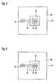
- Figure 5 shows a cover in which the spacing means is formed from two separate adhesive paper labels attached to the cover spaced from each other.
- One of the labels holds the end portion 18 of the welding wire in the outer portion 38 of the slot 32, and a second label holds the wire portion currently withdrawn in the inner portion 36 of the slot.
- the paper labels are ruptured so as to allow the welding wire to escape from the container through the slot.
- Figure 6 shows a third embodiment which largely corresponds to the second embodiment.
- the two labels are formed from a stronger material such as plastic, leather or cardboard.
- the labels are provided with a preformed cut which makes it easier for the welding wire to escape from the labels.
Landscapes
- Engineering & Computer Science (AREA)
- Mechanical Engineering (AREA)
- Physics & Mathematics (AREA)
- Plasma & Fusion (AREA)
- Packaging Of Annular Or Rod-Shaped Articles, Wearing Apparel, Cassettes, Or The Like (AREA)
- Storage Of Web-Like Or Filamentary Materials (AREA)
- Package Closures (AREA)
- Table Devices Or Equipment (AREA)
- Closing Of Containers (AREA)
Claims (19)
- Combinaison d'un couvercle (24) et d'un réceptacle (10, 12) de fil à souder qui contient du fil à souder, le couvercle présentant une face supérieure (26) pourvue d'une fente (32) à travers laquelle le fil à souder (16) peut être retiré du réceptacle, caractérisée en ce que la fente (32) présente un moyen d'écartement (34) définissant un tronçon intérieur (36) et un tronçon extérieur (38) de la fente de telle sorte que du fil à souder s'étendant à travers le tronçon intérieur de la fente est maintenu à distance du fil à souder s'étendant à travers le tronçon extérieur de la fente, et en ce que le moyen d'écartement (34) est réalisé de manière à pouvoir être dévié de telle sorte que le fil à souder peut passer par le moyen d'écartement lorsque le moyen d'écartement se trouve dans un état dévié.
- Combinaison selon la revendication 1, caractérisée en ce que le moyen d'écartement (34) est réalisé de manière à ce que son effet d'écartement puisse être surmonté par le fil à souder.
- Combinaison selon la revendication 1 ou la revendication 2, caractérisée en ce que le moyen d'écartement (34) est fixé au couvercle (24) de manière à être au moins partiellement détachable du couvercle.
- Combinaison selon l'une des revendications 1 à 3, caractérisée en ce que le moyen d'écartement est réalisé de manière à être destructible.
- Combinaison selon l'une des revendications précédentes, caractérisée en ce que le moyen d'écartement (34) est formé à partir d'une bande adhésive.
- Combinaison selon l'une des revendications 1 à 4, caractérisée en ce que le moyen d'écartement (34) est formé d'une étiquette attachée au couvercle.
- Combinaison selon la revendication 5 ou la revendication 6, caractérisée en ce que le moyen d'écartement (34) est formé d'une étiquette intérieure et d'une étiquette extérieure.
- Combinaison selon la revendication 7, caractérisée en ce que les étiquettes intérieure et extérieure ont chacune une ouverture pour le fil à souder.
- Combinaison selon la revendication 5, caractérisée en ce que le moyen d'écartement (34) est formé d'une seule bande adhésive.
- Combinaison selon l'une des revendications 1 à 4, caractérisée en ce que le moyen d'écartement (34) est une plaque fixée à la face supérieure (26) du couvercle (24).
- Combinaison selon la revendication 10, caractérisée en ce que la plaque est fixée à la face supérieure du couvercle seulement d'un côté de la fente (32).
- Combinaison selon l'une des revendications précédentes, caractérisée en ce que le moyen d'écartement (34) est en matière plastique.
- Combinaison selon la revendication 1, caractérisée en ce que le moyen d'écartement est composé d'au moins un tronçon étroit de la fente où les bords de la fente sont agencés opposés les uns aux autres avec une distance inférieure au diamètre du fil à souder.
- Combinaison selon l'une des revendications précédentes, caractérisée en ce que la fente (32) s'étend depuis un bord du couvercle vers le centre et au-delà du centre.
- Combinaison selon l'une des revendications précédentes, caractérisée en ce qu'un tronçon surélevé (30) est prévu au centre du couvercle.
- Combinaison selon la revendication 15, caractérisée en ce que le tronçon surélevé a la forme d'un tronc de cône.
- Combinaison selon la revendication 15, caractérisée en ce que le tronçon surélevé a la forme d'une pyramide tronconique (30).
- Combinaison selon la revendication 17, caractérisée en ce que la fente (32) traverse une face latérale et une face supérieure de la pyramide tronconique et s'étend sur presque toute la face latérale opposée de la pyramide tronconique.
- Combinaison selon l'une des revendications précédentes, caractérisée en ce que la fente (32) présente une largeur d'environ 20 mm.
Applications Claiming Priority (2)
| Application Number | Priority Date | Filing Date | Title |
|---|---|---|---|
| DE10360466A DE10360466A1 (de) | 2003-12-22 | 2003-12-22 | Abdeckung für einen Schweißdrahtbehälter |
| PCT/EP2004/014554 WO2005061168A1 (fr) | 2003-12-22 | 2004-12-21 | Couvercle pour receptacle de fil a souder |
Publications (2)
| Publication Number | Publication Date |
|---|---|
| EP1711299A1 EP1711299A1 (fr) | 2006-10-18 |
| EP1711299B1 true EP1711299B1 (fr) | 2010-10-06 |
Family
ID=34673019
Family Applications (1)
| Application Number | Title | Priority Date | Filing Date |
|---|---|---|---|
| EP04804150A Expired - Lifetime EP1711299B1 (fr) | 2003-12-22 | 2004-12-21 | Couvercle pour receptacle de fil a souder |
Country Status (8)
| Country | Link |
|---|---|
| US (1) | US20070272573A1 (fr) |
| EP (1) | EP1711299B1 (fr) |
| AT (1) | ATE483546T1 (fr) |
| CA (1) | CA2547857A1 (fr) |
| DE (2) | DE10360466A1 (fr) |
| DK (1) | DK1711299T3 (fr) |
| ES (1) | ES2354161T3 (fr) |
| WO (1) | WO2005061168A1 (fr) |
Families Citing this family (20)
| Publication number | Priority date | Publication date | Assignee | Title |
|---|---|---|---|---|
| DE102006022841A1 (de) | 2006-03-30 | 2007-10-04 | Sidergas Spa | Halterung für eine Schweißdrahtspule |
| US7410111B2 (en) | 2006-06-16 | 2008-08-12 | Lincoln Global, Inc. | Guide ring for coiled wire |
| US7690593B2 (en) | 2007-07-09 | 2010-04-06 | Lincoln Global, Inc. | Welding wire guide ring |
| US7721985B2 (en) | 2007-07-09 | 2010-05-25 | Lincoln Global, Inc. | Welding wire guide ring |
| EP2288469B1 (fr) | 2008-05-27 | 2013-04-10 | AWDS Technologies SRL | Système de guidage de fil |
| EP2174741B1 (fr) | 2008-10-07 | 2012-06-20 | SIDERGAS SpA | Couvercle pour conteneur de fil-électrode à souder |
| US7938352B2 (en) | 2009-03-10 | 2011-05-10 | Lincoln Global, Inc. | Wire dispensing apparatus for packaged wire |
| US8235210B2 (en) | 2009-04-27 | 2012-08-07 | Lincoln Global, Inc. | Welding wire container cover and container containing same |
| EP2456590B1 (fr) | 2009-07-20 | 2015-09-09 | AWDS Technologies SRL | Gaine de guidage de fil, en particulier une gaine de fil de soudure, comprenant un moyen de sollicitation entre des corps de guidage articulés |
| US8127923B2 (en) | 2009-11-13 | 2012-03-06 | Sidergas Spa | Container for welding wire |
| US8389901B1 (en) | 2010-05-27 | 2013-03-05 | Awds Technologies Srl | Welding wire guiding liner |
| US8882018B2 (en) | 2011-12-19 | 2014-11-11 | Sidergas Spa | Retainer for welding wire container and welding wire container with retainer |
| US10294065B2 (en) | 2013-06-06 | 2019-05-21 | Sidergas Spa | Retainer for a welding wire container and welding wire container |
| US10343231B2 (en) | 2014-05-28 | 2019-07-09 | Awds Technologies Srl | Wire feeding system |
| US10010962B1 (en) | 2014-09-09 | 2018-07-03 | Awds Technologies Srl | Module and system for controlling and recording welding data, and welding wire feeder |
| US10350696B2 (en) | 2015-04-06 | 2019-07-16 | Awds Technologies Srl | Wire feed system and method of controlling feed of welding wire |
| US9975728B2 (en) | 2015-09-10 | 2018-05-22 | Sidergas Spa | Wire container lid, wire container and wire feeding system |
| US9950857B1 (en) | 2016-10-17 | 2018-04-24 | Sidergas Spa | Welding wire container |
| US11278981B2 (en) | 2020-01-20 | 2022-03-22 | Awds Technologies Srl | Device for imparting a torsional force onto a wire |
| US11174121B2 (en) | 2020-01-20 | 2021-11-16 | Awds Technologies Srl | Device for imparting a torsional force onto a wire |
Family Cites Families (15)
| Publication number | Priority date | Publication date | Assignee | Title |
|---|---|---|---|---|
| US2580900A (en) * | 1950-02-23 | 1952-01-01 | Mandel E Epstein | Package for twine, rope, or the like |
| FR1146262A (fr) * | 1956-03-24 | 1957-11-08 | Geoffrey-Delore Sa | Dispositif pour dévider en continu du fil à partir de fûts |
| US3096951A (en) * | 1962-01-02 | 1963-07-09 | New Haven Wire & Cable Inc | Wire package and reel therefor |
| US3823894A (en) * | 1973-01-04 | 1974-07-16 | Anaconda Co | Strand package |
| US4274607A (en) * | 1979-12-03 | 1981-06-23 | Belden Corporation | Guide device for use in elongate filament dispensing package and the like |
| US4451014A (en) * | 1982-08-11 | 1984-05-29 | Mossberg Industries, Inc. | Wire storing and dereeling apparatus |
| JPS6082276A (ja) * | 1983-10-06 | 1985-05-10 | Kobe Steel Ltd | パツク入り溶接用ワイヤのワイヤ継ぎ方法 |
| JPS6082275A (ja) * | 1983-10-06 | 1985-05-10 | Kobe Steel Ltd | パツク入り溶接用ワイヤのワイヤ継ぎ方法 |
| CA2071419C (fr) * | 1991-06-18 | 1996-03-19 | William Dimmett Cooper | Rondelle retenue pour contenant a bobine de fil a souder |
| US5553810A (en) * | 1994-02-23 | 1996-09-10 | The Lincoln Electric Company | Covers for welding wire reels |
| US6016911A (en) * | 1999-02-19 | 2000-01-25 | Chen; Hua-Mei | Package for a reel of wire |
| ES2203052T3 (es) * | 1999-05-31 | 2004-04-01 | C.I.F.E. S.R.L. | Caja de carton para contener y distribuir hilo. |
| SE0101749L (sv) | 2001-05-18 | 2002-04-23 | Esab Ab | Anordning vid svetstrådsmatning, trådorienteringslöpare, metod och användning |
| US6715608B1 (en) * | 2001-11-06 | 2004-04-06 | Lincoln Global, Inc. | Package for welding wire |
| US7017742B2 (en) * | 2002-04-10 | 2006-03-28 | Hobart Brothers Company, | Recyclable container adapted for movement by a lifting device and method for making same |
-
2003
- 2003-12-22 DE DE10360466A patent/DE10360466A1/de not_active Withdrawn
-
2004
- 2004-12-21 AT AT04804150T patent/ATE483546T1/de active
- 2004-12-21 US US10/596,697 patent/US20070272573A1/en not_active Abandoned
- 2004-12-21 DE DE602004029502T patent/DE602004029502D1/de not_active Expired - Lifetime
- 2004-12-21 DK DK04804150.3T patent/DK1711299T3/da active
- 2004-12-21 EP EP04804150A patent/EP1711299B1/fr not_active Expired - Lifetime
- 2004-12-21 CA CA002547857A patent/CA2547857A1/fr not_active Abandoned
- 2004-12-21 WO PCT/EP2004/014554 patent/WO2005061168A1/fr not_active Ceased
- 2004-12-21 ES ES04804150T patent/ES2354161T3/es not_active Expired - Lifetime
Also Published As
| Publication number | Publication date |
|---|---|
| US20070272573A1 (en) | 2007-11-29 |
| WO2005061168A1 (fr) | 2005-07-07 |
| DE10360466A1 (de) | 2005-07-14 |
| ATE483546T1 (de) | 2010-10-15 |
| DE602004029502D1 (de) | 2010-11-18 |
| EP1711299A1 (fr) | 2006-10-18 |
| DK1711299T3 (da) | 2011-01-31 |
| ES2354161T3 (es) | 2011-03-10 |
| CA2547857A1 (fr) | 2005-07-07 |
Similar Documents
| Publication | Publication Date | Title |
|---|---|---|
| EP1711299B1 (fr) | Couvercle pour receptacle de fil a souder | |
| EP1714930B1 (fr) | Couvercle pour un réceptacle de fil à souder | |
| EP2220984B1 (fr) | Distributeur de lingettes doté de fonctionnalités anti-amas et anti-recul | |
| CA2047011C (fr) | Distribution de sacs en plastique | |
| USD610856S1 (en) | Recyclable wine-dispensing container | |
| EP2174741B1 (fr) | Couvercle pour conteneur de fil-électrode à souder | |
| US6557740B1 (en) | Device for removing a pill from its package | |
| WO1997001495A1 (fr) | Etiquette autocollante a bande d'arrachage | |
| WO1998005570A1 (fr) | Dispositif de transport et de fermeture de boites a boisson | |
| WO2003045816A8 (fr) | Emballage a ouverture par dechirure orientee | |
| US20070295853A1 (en) | Mechanism for braking the unwinding of a bundle of metallic wire housed in a drum | |
| SK282585B6 (sk) | Nádobka, najmä na nápoje | |
| US20110174833A1 (en) | Dispenser for z-folded precut wiping materials stored in cardboard cassette packaging | |
| US20040040670A1 (en) | Adhesive tape dispenser | |
| US8991656B2 (en) | Container | |
| JP2008205406A (ja) | テープフィーダ | |
| JP5426331B2 (ja) | ラベル貼着装置 | |
| EP1474339B1 (fr) | Pile de sacs | |
| US20020195204A1 (en) | Tape dispenser provided with means to prevent bodily injury of a user thereof | |
| NL8002146A (nl) | Afgifte-inrichting met garantiezegel-lip, bruikbaar voor spuitbuskleppen. | |
| JP4792564B2 (ja) | パウチ容器用スパウト及びパウチ容器 | |
| KR101472834B1 (ko) | 접착테이프용 디스펜서 | |
| US20040206665A1 (en) | Transport tape | |
| EP1880952A1 (fr) | Pile de sacs | |
| US20260048918A1 (en) | Re-closable container with zipper |
Legal Events
| Date | Code | Title | Description |
|---|---|---|---|
| PUAI | Public reference made under article 153(3) epc to a published international application that has entered the european phase |
Free format text: ORIGINAL CODE: 0009012 |
|
| 17P | Request for examination filed |
Effective date: 20060518 |
|
| AK | Designated contracting states |
Kind code of ref document: A1 Designated state(s): AT BE BG CH CY CZ DE DK EE ES FI FR GB GR HU IE IS IT LI LT LU MC NL PL PT RO SE SI SK TR |
|
| DAX | Request for extension of the european patent (deleted) | ||
| 17Q | First examination report despatched |
Effective date: 20080331 |
|
| GRAP | Despatch of communication of intention to grant a patent |
Free format text: ORIGINAL CODE: EPIDOSNIGR1 |
|
| GRAS | Grant fee paid |
Free format text: ORIGINAL CODE: EPIDOSNIGR3 |
|
| GRAA | (expected) grant |
Free format text: ORIGINAL CODE: 0009210 |
|
| AK | Designated contracting states |
Kind code of ref document: B1 Designated state(s): AT BE BG CH CY CZ DE DK EE ES FI FR GB GR HU IE IS IT LI LT LU MC NL PL PT RO SE SI SK TR |
|
| REG | Reference to a national code |
Ref country code: GB Ref legal event code: FG4D |
|
| REG | Reference to a national code |
Ref country code: CH Ref legal event code: EP |
|
| REG | Reference to a national code |
Ref country code: IE Ref legal event code: FG4D |
|
| REF | Corresponds to: |
Ref document number: 602004029502 Country of ref document: DE Date of ref document: 20101118 Kind code of ref document: P |
|
| REG | Reference to a national code |
Ref country code: NL Ref legal event code: T3 |
|
| REG | Reference to a national code |
Ref country code: DK Ref legal event code: T3 |
|
| REG | Reference to a national code |
Ref country code: SE Ref legal event code: TRGR |
|
| PG25 | Lapsed in a contracting state [announced via postgrant information from national office to epo] |
Ref country code: SI Free format text: LAPSE BECAUSE OF FAILURE TO SUBMIT A TRANSLATION OF THE DESCRIPTION OR TO PAY THE FEE WITHIN THE PRESCRIBED TIME-LIMIT Effective date: 20101006 |
|
| PGFP | Annual fee paid to national office [announced via postgrant information from national office to epo] |
Ref country code: CH Payment date: 20101224 Year of fee payment: 7 |
|
| REG | Reference to a national code |
Ref country code: CH Ref legal event code: NV Representative=s name: BUGNION S.A. |
|
| REG | Reference to a national code |
Ref country code: ES Ref legal event code: FG2A Effective date: 20110228 |
|
| LTIE | Lt: invalidation of european patent or patent extension |
Effective date: 20101006 |
|
| PG25 | Lapsed in a contracting state [announced via postgrant information from national office to epo] |
Ref country code: LT Free format text: LAPSE BECAUSE OF FAILURE TO SUBMIT A TRANSLATION OF THE DESCRIPTION OR TO PAY THE FEE WITHIN THE PRESCRIBED TIME-LIMIT Effective date: 20101006 |
|
| PG25 | Lapsed in a contracting state [announced via postgrant information from national office to epo] |
Ref country code: PT Free format text: LAPSE BECAUSE OF FAILURE TO SUBMIT A TRANSLATION OF THE DESCRIPTION OR TO PAY THE FEE WITHIN THE PRESCRIBED TIME-LIMIT Effective date: 20110207 Ref country code: IS Free format text: LAPSE BECAUSE OF FAILURE TO SUBMIT A TRANSLATION OF THE DESCRIPTION OR TO PAY THE FEE WITHIN THE PRESCRIBED TIME-LIMIT Effective date: 20110206 Ref country code: FI Free format text: LAPSE BECAUSE OF FAILURE TO SUBMIT A TRANSLATION OF THE DESCRIPTION OR TO PAY THE FEE WITHIN THE PRESCRIBED TIME-LIMIT Effective date: 20101006 Ref country code: BG Free format text: LAPSE BECAUSE OF FAILURE TO SUBMIT A TRANSLATION OF THE DESCRIPTION OR TO PAY THE FEE WITHIN THE PRESCRIBED TIME-LIMIT Effective date: 20110106 |
|
| PGFP | Annual fee paid to national office [announced via postgrant information from national office to epo] |
Ref country code: CZ Payment date: 20101221 Year of fee payment: 7 |
|
| PG25 | Lapsed in a contracting state [announced via postgrant information from national office to epo] |
Ref country code: GR Free format text: LAPSE BECAUSE OF FAILURE TO SUBMIT A TRANSLATION OF THE DESCRIPTION OR TO PAY THE FEE WITHIN THE PRESCRIBED TIME-LIMIT Effective date: 20110107 |
|
| PG25 | Lapsed in a contracting state [announced via postgrant information from national office to epo] |
Ref country code: MC Free format text: LAPSE BECAUSE OF NON-PAYMENT OF DUE FEES Effective date: 20101231 Ref country code: EE Free format text: LAPSE BECAUSE OF FAILURE TO SUBMIT A TRANSLATION OF THE DESCRIPTION OR TO PAY THE FEE WITHIN THE PRESCRIBED TIME-LIMIT Effective date: 20101006 |
|
| PLBE | No opposition filed within time limit |
Free format text: ORIGINAL CODE: 0009261 |
|
| STAA | Information on the status of an ep patent application or granted ep patent |
Free format text: STATUS: NO OPPOSITION FILED WITHIN TIME LIMIT |
|
| PG25 | Lapsed in a contracting state [announced via postgrant information from national office to epo] |
Ref country code: SK Free format text: LAPSE BECAUSE OF FAILURE TO SUBMIT A TRANSLATION OF THE DESCRIPTION OR TO PAY THE FEE WITHIN THE PRESCRIBED TIME-LIMIT Effective date: 20101006 Ref country code: RO Free format text: LAPSE BECAUSE OF FAILURE TO SUBMIT A TRANSLATION OF THE DESCRIPTION OR TO PAY THE FEE WITHIN THE PRESCRIBED TIME-LIMIT Effective date: 20101006 Ref country code: PL Free format text: LAPSE BECAUSE OF FAILURE TO SUBMIT A TRANSLATION OF THE DESCRIPTION OR TO PAY THE FEE WITHIN THE PRESCRIBED TIME-LIMIT Effective date: 20101006 |
|
| 26N | No opposition filed |
Effective date: 20110707 |
|
| PG25 | Lapsed in a contracting state [announced via postgrant information from national office to epo] |
Ref country code: IE Free format text: LAPSE BECAUSE OF NON-PAYMENT OF DUE FEES Effective date: 20101221 |
|
| REG | Reference to a national code |
Ref country code: DE Ref legal event code: R097 Ref document number: 602004029502 Country of ref document: DE Effective date: 20110707 |
|
| PG25 | Lapsed in a contracting state [announced via postgrant information from national office to epo] |
Ref country code: CZ Free format text: LAPSE BECAUSE OF NON-PAYMENT OF DUE FEES Effective date: 20111221 |
|
| REG | Reference to a national code |
Ref country code: CH Ref legal event code: PL |
|
| PG25 | Lapsed in a contracting state [announced via postgrant information from national office to epo] |
Ref country code: CY Free format text: LAPSE BECAUSE OF FAILURE TO SUBMIT A TRANSLATION OF THE DESCRIPTION OR TO PAY THE FEE WITHIN THE PRESCRIBED TIME-LIMIT Effective date: 20101006 |
|
| PG25 | Lapsed in a contracting state [announced via postgrant information from national office to epo] |
Ref country code: HU Free format text: LAPSE BECAUSE OF FAILURE TO SUBMIT A TRANSLATION OF THE DESCRIPTION OR TO PAY THE FEE WITHIN THE PRESCRIBED TIME-LIMIT Effective date: 20110407 Ref country code: LU Free format text: LAPSE BECAUSE OF NON-PAYMENT OF DUE FEES Effective date: 20101221 |
|
| PG25 | Lapsed in a contracting state [announced via postgrant information from national office to epo] |
Ref country code: TR Free format text: LAPSE BECAUSE OF FAILURE TO SUBMIT A TRANSLATION OF THE DESCRIPTION OR TO PAY THE FEE WITHIN THE PRESCRIBED TIME-LIMIT Effective date: 20101006 Ref country code: CH Free format text: LAPSE BECAUSE OF NON-PAYMENT OF DUE FEES Effective date: 20111231 Ref country code: LI Free format text: LAPSE BECAUSE OF NON-PAYMENT OF DUE FEES Effective date: 20111231 |
|
| PGFP | Annual fee paid to national office [announced via postgrant information from national office to epo] |
Ref country code: SE Payment date: 20141219 Year of fee payment: 11 Ref country code: ES Payment date: 20141226 Year of fee payment: 11 Ref country code: GB Payment date: 20141219 Year of fee payment: 11 Ref country code: DK Payment date: 20141219 Year of fee payment: 11 |
|
| PGFP | Annual fee paid to national office [announced via postgrant information from national office to epo] |
Ref country code: AT Payment date: 20141222 Year of fee payment: 11 Ref country code: NL Payment date: 20141219 Year of fee payment: 11 Ref country code: FR Payment date: 20141219 Year of fee payment: 11 |
|
| PGFP | Annual fee paid to national office [announced via postgrant information from national office to epo] |
Ref country code: IT Payment date: 20141222 Year of fee payment: 11 |
|
| PGFP | Annual fee paid to national office [announced via postgrant information from national office to epo] |
Ref country code: DE Payment date: 20141218 Year of fee payment: 11 |
|
| PGFP | Annual fee paid to national office [announced via postgrant information from national office to epo] |
Ref country code: BE Payment date: 20141219 Year of fee payment: 11 |
|
| PG25 | Lapsed in a contracting state [announced via postgrant information from national office to epo] |
Ref country code: BE Free format text: LAPSE BECAUSE OF NON-PAYMENT OF DUE FEES Effective date: 20151231 |
|
| REG | Reference to a national code |
Ref country code: DE Ref legal event code: R119 Ref document number: 602004029502 Country of ref document: DE |
|
| REG | Reference to a national code |
Ref country code: DK Ref legal event code: EBP Effective date: 20151231 |
|
| REG | Reference to a national code |
Ref country code: SE Ref legal event code: EUG |
|
| REG | Reference to a national code |
Ref country code: AT Ref legal event code: MM01 Ref document number: 483546 Country of ref document: AT Kind code of ref document: T Effective date: 20151221 |
|
| GBPC | Gb: european patent ceased through non-payment of renewal fee |
Effective date: 20151221 |
|
| PG25 | Lapsed in a contracting state [announced via postgrant information from national office to epo] |
Ref country code: SE Free format text: LAPSE BECAUSE OF NON-PAYMENT OF DUE FEES Effective date: 20151222 |
|
| REG | Reference to a national code |
Ref country code: NL Ref legal event code: MM Effective date: 20160101 |
|
| REG | Reference to a national code |
Ref country code: FR Ref legal event code: ST Effective date: 20160831 |
|
| PG25 | Lapsed in a contracting state [announced via postgrant information from national office to epo] |
Ref country code: NL Free format text: LAPSE BECAUSE OF NON-PAYMENT OF DUE FEES Effective date: 20160101 Ref country code: GB Free format text: LAPSE BECAUSE OF NON-PAYMENT OF DUE FEES Effective date: 20151221 Ref country code: DE Free format text: LAPSE BECAUSE OF NON-PAYMENT OF DUE FEES Effective date: 20160701 |
|
| PG25 | Lapsed in a contracting state [announced via postgrant information from national office to epo] |
Ref country code: AT Free format text: LAPSE BECAUSE OF NON-PAYMENT OF DUE FEES Effective date: 20151221 Ref country code: FR Free format text: LAPSE BECAUSE OF NON-PAYMENT OF DUE FEES Effective date: 20151231 |
|
| PG25 | Lapsed in a contracting state [announced via postgrant information from national office to epo] |
Ref country code: IT Free format text: LAPSE BECAUSE OF NON-PAYMENT OF DUE FEES Effective date: 20151221 |
|
| REG | Reference to a national code |
Ref country code: ES Ref legal event code: FD2A Effective date: 20170127 |
|
| PG25 | Lapsed in a contracting state [announced via postgrant information from national office to epo] |
Ref country code: DK Free format text: LAPSE BECAUSE OF NON-PAYMENT OF DUE FEES Effective date: 20151231 |
|
| PG25 | Lapsed in a contracting state [announced via postgrant information from national office to epo] |
Ref country code: ES Free format text: LAPSE BECAUSE OF NON-PAYMENT OF DUE FEES Effective date: 20151222 |