EP1712509A2 - Vorrichtung und Verfahren zum Handhaben und Kontrollieren eines Garnes eines Kreuzspulkopfes einer Kreuzspulmaschine während des Startens einer neuen Partie - Google Patents
Vorrichtung und Verfahren zum Handhaben und Kontrollieren eines Garnes eines Kreuzspulkopfes einer Kreuzspulmaschine während des Startens einer neuen Partie Download PDFInfo
- Publication number
- EP1712509A2 EP1712509A2 EP06111874A EP06111874A EP1712509A2 EP 1712509 A2 EP1712509 A2 EP 1712509A2 EP 06111874 A EP06111874 A EP 06111874A EP 06111874 A EP06111874 A EP 06111874A EP 1712509 A2 EP1712509 A2 EP 1712509A2
- Authority
- EP
- European Patent Office
- Prior art keywords
- yarn
- crosswinding
- suction mouth
- pirn
- suction
- Prior art date
- Legal status (The legal status is an assumption and is not a legal conclusion. Google has not performed a legal analysis and makes no representation as to the accuracy of the status listed.)
- Granted
Links
- 238000000034 method Methods 0.000 title claims abstract description 27
- 230000008569 process Effects 0.000 title claims abstract description 21
- 238000005304 joining Methods 0.000 claims abstract description 15
- 238000005520 cutting process Methods 0.000 claims description 15
- 238000004804 winding Methods 0.000 claims description 13
- 230000015572 biosynthetic process Effects 0.000 claims description 3
- 230000000903 blocking effect Effects 0.000 claims description 2
- 238000006467 substitution reaction Methods 0.000 description 4
- 230000009471 action Effects 0.000 description 3
- 230000007547 defect Effects 0.000 description 3
- 230000008859 change Effects 0.000 description 1
- 238000004140 cleaning Methods 0.000 description 1
- 230000001419 dependent effect Effects 0.000 description 1
- 230000000694 effects Effects 0.000 description 1
- 238000003780 insertion Methods 0.000 description 1
- 230000037431 insertion Effects 0.000 description 1
- 238000004519 manufacturing process Methods 0.000 description 1
- 230000007246 mechanism Effects 0.000 description 1
- 238000012986 modification Methods 0.000 description 1
- 230000004048 modification Effects 0.000 description 1
Images



Classifications
-
- B—PERFORMING OPERATIONS; TRANSPORTING
- B65—CONVEYING; PACKING; STORING; HANDLING THIN OR FILAMENTARY MATERIAL
- B65H—HANDLING THIN OR FILAMENTARY MATERIAL, e.g. SHEETS, WEBS, CABLES
- B65H54/00—Winding, coiling, or depositing filamentary material
- B65H54/02—Winding and traversing material on to reels, bobbins, tubes, or like package cores or formers
- B65H54/22—Automatic winding machines, i.e. machines with servicing units for automatically performing end-finding, interconnecting of successive lengths of material, controlling and fault-detecting of the running material and replacing or removing of full or empty cores
- B65H54/26—Automatic winding machines, i.e. machines with servicing units for automatically performing end-finding, interconnecting of successive lengths of material, controlling and fault-detecting of the running material and replacing or removing of full or empty cores having one or more servicing units moving along a plurality of fixed winding units
-
- B—PERFORMING OPERATIONS; TRANSPORTING
- B65—CONVEYING; PACKING; STORING; HANDLING THIN OR FILAMENTARY MATERIAL
- B65H—HANDLING THIN OR FILAMENTARY MATERIAL, e.g. SHEETS, WEBS, CABLES
- B65H65/00—Securing material to cores or formers
-
- B—PERFORMING OPERATIONS; TRANSPORTING
- B65—CONVEYING; PACKING; STORING; HANDLING THIN OR FILAMENTARY MATERIAL
- B65H—HANDLING THIN OR FILAMENTARY MATERIAL, e.g. SHEETS, WEBS, CABLES
- B65H67/00—Replacing or removing cores, receptacles, or completed packages at paying-out, winding, or depositing stations
- B65H67/08—Automatic end-finding and material-interconnecting arrangements
- B65H67/081—Automatic end-finding and material-interconnecting arrangements acting after interruption of the winding process, e.g. yarn breakage, yarn cut or package replacement
-
- B—PERFORMING OPERATIONS; TRANSPORTING
- B65—CONVEYING; PACKING; STORING; HANDLING THIN OR FILAMENTARY MATERIAL
- B65H—HANDLING THIN OR FILAMENTARY MATERIAL, e.g. SHEETS, WEBS, CABLES
- B65H2701/00—Handled material; Storage means
- B65H2701/30—Handled filamentary material
- B65H2701/31—Textiles threads or artificial strands of filaments
Definitions
- the present invention relates to a device and process for handling and controlling the yarn in a crosswinding head of a crosswinding machine during the starting operations of a new lot, or for the contemporaneous replacement of a pirn with a new one and a bobbin with a new tube, around which the yarn coming from the feeding pirn is wound to form a new bobbin.
- crosswinding procedures essentially consist of unwinding operations of the yarn from feeding pirns, cleaning the yarn from possible faults and its crosswinding onto tubes, according to forms and dimensions which vary according to the destination of the yarn.
- the bobbins are normally cylindrical, or truncated-conical with a low conicity, if, on the contrary, the yarn is destined for feeding low-speed machines, the bobbins are truncated-conical with a higher conicity.
- the degree of conicity is selected so as to always ensure a correct unwinding of the bobbins during their final use, in the presence of more or less strong centrifugal forces.
- a crosswinding machine allows the contemporaneous crosswinding of a series of bobbins, i.e. it normally comprises a series of so-called crosswinding heads, positioned side by side, and served by at least one common service device, also called trolley, which can run along the whole crosswinding machine, positioning itself in correspondence with each crosswinding head and which effects, in an automated manner, various operations which are cyclically required by each crosswinding head.
- a common service device also called trolley
- the crosswinding head in the case of the starting of a new lot, or if it is necessary to contemporaneously substitute a pirn and bobbin, the crosswinding head must be stopped, the pirn and bobbin must be removed and a new pirn and a new winding tube, around which a new bobbin must be formed, must be respectively positioned in their place.
- the yarn coming from the new pirn must be moved to the new tube and wound onto the same in order to restart the crosswinding operations.
- each crosswinding head is generally equipped with devices, situated along the run of the yarn from the feeding pirn to the winding bobbin, whose function is to eliminate possible yarn imperfections and remedy possible breakages.
- said defects In the case of yarn defects, in fact, said defects must be located, the yarn must be cut, the faulty part eliminated and the two ends, which have formed on the side of the pirn and bobbin, respectively, must be re-joined.
- the capturing devices of the cut yarn ends normally consist of two suction mouths, for the collection of the yarn end coming from the side of the pirn and from the side of the bobbin, respectively, situated on arms oscillating between a first operating position, corresponding to the pirn and the bobbin, respectively, and a second operating position, in correspondence with the device for joining the yarn ends, also called joiner or knotter.
- the handling and controlling of the yarn during the starting operations of a new lot require the intervention of the common service device which, in cooperation with the devices of the crosswinding head situated along the run of the yarn from the feeding pirn to the winding bobbin, recovers the yarn end coming from the new pirn, positions the new winding tube on the crosswinding head and arranges the yarn end on the new winding tube.
- the suction of the suction mouth situated on the side of the bobbin is stopped, the suction of the suction mouth which is on the side of the bobbin is contemporaneously activated, which takes custody of the yarn end.
- the suction mouth situated on the side of the bobbin is then rotated to its position near the bobbin, where the yarn is collected by the handling device of the common service trolley.
- An objective of the present invention is therefore to collect the yarn end coming from the new pirn and to deliver it to a position which facilitates the intervention of the service trolley, in particular its collection of the yarn to be wound around the new winding tube during the starting operations of a new lot.
- a further objective of the present invention is to guarantee a higher productivity of the crosswinding machine through a higher operating factor.
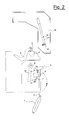
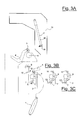
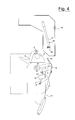
- Figures 1-7 show, in particular, a pirn 1, from which the yarn 2 unravels, which must be delivered to the end of a bobbin-holder arm 4, wherein there is a counter-pin 3 for housing a tube (not shown) around which the yarn 2 will be wound for the formation of the bobbin.
- a slit-plate 5 is shown together with a driving and traversing cylinder 6.
- a suction mouth 7 is shown, for the suction of the yarn 2 ends on the side of the pirn 1, together with a suction mouth 8 for the suction of the yarn 2 ends on the side of the bobbin and a joining device 9.
- the slit-plate 5 has the function of revealing defects of the yarn 2 and possibly cutting it, by means of a cutting device not shown in the figures, but substantially situated in the same position as the slit-plate 5.
- the driving and traversing cylinder 6 carries the yarn 2 according to a backwards and forwards movement along the whole length of the bobbin, so that the yarn 2 is uniformly distributed along the whole length of the bobbin.
- the driving and traversing cylinder 6 is crossed by several grooves, also called cavities, inside which the yarn 2 is passed, maintaining the driving and traversing cylinder 6 in rotation.
- the function of the two suction mouths 7 on the side of the pirn and 8 on the side of the bobbin is, on the contrary, to collect the ends of the yarn 2, for example formed as a result of cutting or breakage of the yarn 2, and connected to the pirn 1 and to the bobbin, respectively, and to carry them to the joining device 9, which re-establishes the continuity of yarn 2.
- a new pirn 1 is arranged in operating position and the end of yarn 2 which comes from the same, is collected by suction on the part of the suction mouth 7.
- the seizing of the yarn 2 end is further assured by a nipper 10, situated at the end of the suction mouth 7, which intervenes by blocking the yarn 2 after a part of the same yarn 2 has been sucked by the suction mouth 7.
- the suction mouth 7, with the nipper 10 closed, is then rotated around the rotation axis A, unwinding the yarn 2 from the pirn 1 and until the same yarn 2 has been induced to cross the joining device 9 (figure 2).
- the closing of the nipper 10 not only ensures the seizure of the yarn 2, but also prevents an excessive amount of yarn from being sucked, as could happen if the seizure of the yarn 2 were left to a continuous suction action exerted by the suction mouth 7.
- the closing of the nipper 10 also makes the suction of the suction mouth 7 superfluous, and this can be deactivated.
- the joiner 9 cuts the yarn 2 and withholds its end coming from the pirn 1.
- the suction of the suction mouth 7 is activated and the nipper 10 is opened to remove the end of the yarn which has remained on the suction mouth 7 after the cutting.
- the joiner 9 withholds the yarn 2 coming from the pirn 1, and once the suction mouth 7 on the side of the pirn has finished its operations, it is ready to return to its standby position.
- the suction mouth 8, on the side of the bobbin is moved towards the yarn 2, along the run of the yarn 2 itself, from the pirn to the joiner 9.
- the suction from the suction mouth 8 is activated and the yarn 2 is released from the joiner 9, as it is sucked by the suction mouth 8.
- the suction mouth 8 on the side of the bobbin is rotated around its rotation axis B and, maintaining its suction activated, it rises, engaging the yarn 2 on its back and unwinding it from the pirn 1 (figure 4).
- the position of the yarn 2 on the back of the suction mouth 8 can be suitably constrained by means of positioning devices.
- the suction inlet 11 of the suction mouth 8 is extremely large (due to the main function of the suction mouth 8, which consists in recovering the end of a broken yarn 2 from the bobbin, said end being in any possible point along the length of the bobbin), the back of the suction mouth 8 narrowing as it proceeds from the aspiration inlet 11 towards the oscillating arm 12 of the suction mouth 8, the yarn 2 can be situated in any position of the back of the suction mouth 8 and, during the rotation of the same around its rotation axis B, in the absence of the positioning means, could also fall to the side.
- the positioning means of the yarn 2 are preferably produced in the form of at least one taper seat 13, situated on the back of the suction mouth 8, V-shaped so that, once the yarn 2 has been collected along the arms of the V-shaped taper seat 13, it tends to converge towards the center of the taper seat 13 itself.
- the positioning means of the yarn comprise two V-shaped taper seats, a first taper seat 13 near the suction inlet 11 of the suction mouth 8, substantially having the same width as the inlet 11 of the suction mouth 8, and a second taper seat 14, near the arm 12 of the suction mouth, which has smaller dimensions.
- the suction mouth 8 engages the yarn 2 first with its portion closer to the aspiration inlet 11. Consequently, due to the action of the first taper seat 13, the yarn 2 has already reached a well-defined position when it engages the whole back of the suction mouth 8 and, therefore, the second taper seat 14.
- the yarn 2 occupies a well-defined position in the space between the part of the back of the suction mouth 8 which is further away from the suction inlet 11 and the slit-plate 5.
- the handling device 15 comprises a telescopic arm 17, at whose end there is a nipping and cutting device 18.
- the calling signal of the service trolley 16 on the part of the crosswinding head engaged in a starting operation of a new lot can be sent at the beginning of the operation, so that the trolley 16 is positioned in correspondence with the crosswinding head before the suction mouth 8 has reached the intervention position of the handling device 15.
- the devices of the trolley 16 which are charged with the doffing operations of the bobbin and its substitution with a new tube are ready to intervene when the suction mouth 8 reaches the intervention position, but the trolley 16 could be compelled to wait.
- the calling signal of the service trolley 16 can be sent subsequently, so that the trolley 16 is positioned in correspondence with the crosswinding head after the suction mouth 8 has reached the intervention position of the handling device 15. In this way, the time the service trolley 16 dedicates to the specific crosswinding head for the doffing operations of the bobbin and its substitution, is minimized, but the crosswinding head could be compelled to wait.
- the nipping and cutting device 18 captures the yarn 2. Subsequently, as shown in figure 7, the nipping and cutting device 18 cuts the yarn 2 and withholds the end coming from the pirn 1. The end of the yarn remaining on the side of the inlet 11 of the suction mouth 8, is sucked and removed.
- the handling mechanism 15 still maintaining its hold on the yarn 2 end coming from the pirn 1, moves away from the crosswinding head, to facilitate the return of the suction mouth 8 to its rest position, by the rotation of the oscillating arm 12 around the rotation axis B.
- the subsequent insertion phases of the yarn 2 end onto the new winding tube can be completed by the handling device 15, according to any of the known techniques, which have the common aspect of engaging the yarn 2 end between the base of the tube and the counterpoint 3 of the bobbin-holder arm 4.
- the handling device 15 of the service trolley 16 subsequently releases the yarn 2, and a new bobbin can be formed, whereas the service trolley 16 becomes available for intervening on other crosswinding heads of the crosswinding machine.
Landscapes
- Engineering & Computer Science (AREA)
- Textile Engineering (AREA)
- Replacing, Conveying, And Pick-Finding For Filamentary Materials (AREA)
- Spinning Or Twisting Of Yarns (AREA)
- Treatment Of Fiber Materials (AREA)
- Filamentary Materials, Packages, And Safety Devices Therefor (AREA)
Applications Claiming Priority (1)
| Application Number | Priority Date | Filing Date | Title |
|---|---|---|---|
| IT000628A ITMI20050628A1 (it) | 2005-04-13 | 2005-04-13 | Dispositivo e procedimento per la manipolazione e il controllo del filo in una testa di roccatura di una macchina roccatrice nelle operazioni di avvio di una nuova partira |
Publications (3)
| Publication Number | Publication Date |
|---|---|
| EP1712509A2 true EP1712509A2 (de) | 2006-10-18 |
| EP1712509A3 EP1712509A3 (de) | 2008-01-30 |
| EP1712509B1 EP1712509B1 (de) | 2010-05-26 |
Family
ID=36754835
Family Applications (1)
| Application Number | Title | Priority Date | Filing Date |
|---|---|---|---|
| EP06111874A Expired - Lifetime EP1712509B1 (de) | 2005-04-13 | 2006-03-29 | Vorrichtung und Verfahren zum Handhaben und Kontrollieren eines Garnes eines Kreuzspulkopfes einer Kreuzspulmaschine während des Startens einer neuen Partie |
Country Status (6)
| Country | Link |
|---|---|
| US (1) | US20060230739A1 (de) |
| EP (1) | EP1712509B1 (de) |
| CN (1) | CN1847130B (de) |
| AT (1) | ATE469090T1 (de) |
| DE (1) | DE602006014465D1 (de) |
| IT (1) | ITMI20050628A1 (de) |
Cited By (3)
| Publication number | Priority date | Publication date | Assignee | Title |
|---|---|---|---|---|
| DE102008050070A1 (de) | 2008-10-01 | 2010-04-08 | Oerlikon Textile Gmbh & Co. Kg | Vorrichtung zur automatischen Inbetriebnahme einer Arbeitsstelle einer Kreuzspulen herstellenden Textilmaschine |
| WO2017178312A1 (de) * | 2016-04-15 | 2017-10-19 | Oerlikon Textile Gmbh & Co. Kg | Vorrichtung zum aufwickeln eines fadens |
| EP3312116A1 (de) * | 2016-10-19 | 2018-04-25 | Murata Machinery, Ltd. | Garnaufwicklungsvorrichtung und paketrotationsstoppverfahren |
Families Citing this family (4)
| Publication number | Priority date | Publication date | Assignee | Title |
|---|---|---|---|---|
| DE102016108423A1 (de) * | 2016-05-06 | 2017-11-09 | Rieter Ingolstadt Gmbh | Verfahren zum Handhaben eines Fadenendes und Spulstelle |
| CN108439072B (zh) * | 2018-03-07 | 2023-06-27 | 青岛宏大纺织机械有限责任公司 | 一种落筒小车的生头装置及生头方法 |
| CN111302152A (zh) * | 2020-03-26 | 2020-06-19 | 青岛宏大纺织机械有限责任公司 | 一种控制管纱吸嘴准确送纱的装置及方法 |
| CN114803711B (zh) * | 2021-01-18 | 2025-07-15 | 深圳市微埃智能科技有限公司 | 投料装置及投纱机器人 |
Citations (3)
| Publication number | Priority date | Publication date | Assignee | Title |
|---|---|---|---|---|
| US4411128A (en) | 1980-09-26 | 1983-10-25 | Murata Kikai Kabushiki Kaisha | Method and apparatus for splicing spun yarns |
| US4630433A (en) | 1984-11-12 | 1986-12-23 | Mesdan S.P.A. | Method for the splicing of textile threads by means of a compressed gas, and splicing device for the accomplishment of the method |
| EP0717001A1 (de) | 1994-12-15 | 1996-06-19 | SAVIO MACCHINE TESSILI S.r.l. | Verfahren und Vorrichtung zur Durchführung eines flexibelen und modulierenden Wickelzyklus |
Family Cites Families (5)
| Publication number | Priority date | Publication date | Assignee | Title |
|---|---|---|---|---|
| JPS5949332B2 (ja) * | 1976-06-25 | 1984-12-01 | 村田機械株式会社 | 紡糸を止めずに糸継する方法 |
| DE19836702A1 (de) * | 1998-08-13 | 2000-02-17 | Schlafhorst & Co W | Kreuzspulen herstellende Textilmaschine |
| DE10007950A1 (de) * | 2000-02-22 | 2001-08-23 | Schlafhorst & Co W | Vorrichtung zur Inbetriebnahme einer Arbeitsstelle einer Kreuzspulen herstellenden Textilmaschine |
| JP3646682B2 (ja) * | 2001-02-28 | 2005-05-11 | 村田機械株式会社 | 自動ワインダにおける巻取管への糸装着方法及び自動ワインダ |
| DE10257804A1 (de) * | 2002-12-11 | 2004-07-01 | Saurer Gmbh & Co. Kg | Verfahren und Vorrichtung zur Inbetriebnahme einer Arbeitsstelle einer Kreuzspulen herstellenden Textilmaschine |
-
2005
- 2005-04-13 IT IT000628A patent/ITMI20050628A1/it unknown
-
2006
- 2006-03-29 DE DE602006014465T patent/DE602006014465D1/de not_active Expired - Lifetime
- 2006-03-29 AT AT06111874T patent/ATE469090T1/de not_active IP Right Cessation
- 2006-03-29 EP EP06111874A patent/EP1712509B1/de not_active Expired - Lifetime
- 2006-04-03 US US11/396,858 patent/US20060230739A1/en not_active Abandoned
- 2006-04-13 CN CN2006100736345A patent/CN1847130B/zh not_active Expired - Fee Related
Patent Citations (4)
| Publication number | Priority date | Publication date | Assignee | Title |
|---|---|---|---|---|
| US4411128A (en) | 1980-09-26 | 1983-10-25 | Murata Kikai Kabushiki Kaisha | Method and apparatus for splicing spun yarns |
| US4411128B1 (de) | 1980-09-26 | 1990-04-10 | Murata Machinery Ltd | |
| US4630433A (en) | 1984-11-12 | 1986-12-23 | Mesdan S.P.A. | Method for the splicing of textile threads by means of a compressed gas, and splicing device for the accomplishment of the method |
| EP0717001A1 (de) | 1994-12-15 | 1996-06-19 | SAVIO MACCHINE TESSILI S.r.l. | Verfahren und Vorrichtung zur Durchführung eines flexibelen und modulierenden Wickelzyklus |
Cited By (5)
| Publication number | Priority date | Publication date | Assignee | Title |
|---|---|---|---|---|
| DE102008050070A1 (de) | 2008-10-01 | 2010-04-08 | Oerlikon Textile Gmbh & Co. Kg | Vorrichtung zur automatischen Inbetriebnahme einer Arbeitsstelle einer Kreuzspulen herstellenden Textilmaschine |
| CN101712424B (zh) * | 2008-10-01 | 2012-09-05 | 欧瑞康纺织有限及两合公司 | 自动启动制造交叉卷绕筒子的纺织机械工位的方法 |
| WO2017178312A1 (de) * | 2016-04-15 | 2017-10-19 | Oerlikon Textile Gmbh & Co. Kg | Vorrichtung zum aufwickeln eines fadens |
| CN109071145A (zh) * | 2016-04-15 | 2018-12-21 | 欧瑞康纺织有限及两合公司 | 用于卷绕线的设备 |
| EP3312116A1 (de) * | 2016-10-19 | 2018-04-25 | Murata Machinery, Ltd. | Garnaufwicklungsvorrichtung und paketrotationsstoppverfahren |
Also Published As
| Publication number | Publication date |
|---|---|
| DE602006014465D1 (de) | 2010-07-08 |
| ITMI20050628A1 (it) | 2006-10-14 |
| CN1847130B (zh) | 2012-06-27 |
| EP1712509B1 (de) | 2010-05-26 |
| EP1712509A3 (de) | 2008-01-30 |
| ATE469090T1 (de) | 2010-06-15 |
| US20060230739A1 (en) | 2006-10-19 |
| CN1847130A (zh) | 2006-10-18 |
Similar Documents
| Publication | Publication Date | Title |
|---|---|---|
| US3295775A (en) | Method and apparatus for readying the winding operation of yarn supply coils on coil winding machines | |
| CN1028039C (zh) | 在气流纺纱装置中连接纱线的方法和装置 | |
| JP2730585B2 (ja) | 紡績運転を迅速に再開する方法と装置 | |
| US20030029153A1 (en) | Service unit for restarting the spinning of work stations in an open-end spinning machine | |
| CN107055212B (zh) | 用于运行工位的方法和工位 | |
| CN103628198A (zh) | 自由端气流纺纱机工位的运行方法和装置 | |
| EP1712504B1 (de) | Vorrichtung und Verfahren zum Handhaben und Steuern eines Fadens in einem Kreuzwickelkopf einer Kreuzwickelmaschine beim Auswechseln von Spulen | |
| US5634602A (en) | Open end spinning machine with associated service device | |
| CN106467256B (zh) | 在卷绕机的卷绕工位上连接顶纱和底纱的方法和卷绕工位 | |
| US5950957A (en) | Bobbin winding unit of a textile machine for producing cross-wound bobbins | |
| EP1712509B1 (de) | Vorrichtung und Verfahren zum Handhaben und Kontrollieren eines Garnes eines Kreuzspulkopfes einer Kreuzspulmaschine während des Startens einer neuen Partie | |
| CN100545332C (zh) | 自动落纱动作方法和落纱装置 | |
| JP3698873B2 (ja) | 糸条パッケージの形成方法および形成装置 | |
| US6662542B2 (en) | Open-end spinning device and process for temporary receiving a yarn | |
| JP2019199363A (ja) | 糸継ぎされる糸片と排出される糸片を分離する方法、加圧ローラユニット及び吸引ノズル | |
| JP2006521981A (ja) | 繊維機械における糸ボビンの位置決め・取出し装置 | |
| EP4101956A1 (de) | Spinnmaschine mit halbautomatischem doffing und verfahren zum halbautomatischen doffing in einer spinnmaschine | |
| US20030038205A1 (en) | Service unit for a textile machine producing cheeses | |
| CN107963512B (zh) | 纱线卷取装置以及卷装的旋转停止方法 | |
| CN111747233B (zh) | 用于在纺织机工位产生接纱连接的方法以及纺织机工位 | |
| EP1524229B1 (de) | Vorrichtung und Verfahren zum Bilden der Fadenreservewicklung auf Wickelhülsen in Offenend-Spinnmaschinen | |
| JP2023142771A (ja) | 糸巻取機及び糸巻取方法 | |
| EP4467497B1 (de) | Garnwickler | |
| US3345004A (en) | Multiple winder with automatic thread positioning | |
| EP0417849A1 (de) | Verfahren zum Entfernen des am Ende der Spulhülse geklemmten und aufgewickelten Garnteiles und eine Vorrichtung zum Durchführen des Verfahrens |
Legal Events
| Date | Code | Title | Description |
|---|---|---|---|
| PUAI | Public reference made under article 153(3) epc to a published international application that has entered the european phase |
Free format text: ORIGINAL CODE: 0009012 |
|
| AK | Designated contracting states |
Kind code of ref document: A2 Designated state(s): AT BE BG CH CY CZ DE DK EE ES FI FR GB GR HU IE IS IT LI LT LU LV MC NL PL PT RO SE SI SK TR |
|
| AX | Request for extension of the european patent |
Extension state: AL BA HR MK YU |
|
| PUAL | Search report despatched |
Free format text: ORIGINAL CODE: 0009013 |
|
| AK | Designated contracting states |
Kind code of ref document: A3 Designated state(s): AT BE BG CH CY CZ DE DK EE ES FI FR GB GR HU IE IS IT LI LT LU LV MC NL PL PT RO SE SI SK TR |
|
| AX | Request for extension of the european patent |
Extension state: AL BA HR MK YU |
|
| RIC1 | Information provided on ipc code assigned before grant |
Ipc: B65H 67/04 20060101ALI20071227BHEP Ipc: B65H 67/08 20060101ALI20071227BHEP Ipc: B65H 67/06 20060101ALI20071227BHEP Ipc: B65H 54/26 20060101AFI20071227BHEP |
|
| 17P | Request for examination filed |
Effective date: 20080630 |
|
| 17Q | First examination report despatched |
Effective date: 20080804 |
|
| AKX | Designation fees paid |
Designated state(s): AT BE BG CH CY CZ DE DK EE ES FI FR GB GR HU IE IS IT LI LT LU LV MC NL PL PT RO SE SI SK TR |
|
| GRAP | Despatch of communication of intention to grant a patent |
Free format text: ORIGINAL CODE: EPIDOSNIGR1 |
|
| GRAS | Grant fee paid |
Free format text: ORIGINAL CODE: EPIDOSNIGR3 |
|
| GRAA | (expected) grant |
Free format text: ORIGINAL CODE: 0009210 |
|
| AK | Designated contracting states |
Kind code of ref document: B1 Designated state(s): AT BE BG CH CY CZ DE DK EE ES FI FR GB GR HU IE IS IT LI LT LU LV MC NL PL PT RO SE SI SK TR |
|
| REG | Reference to a national code |
Ref country code: GB Ref legal event code: FG4D |
|
| REG | Reference to a national code |
Ref country code: CH Ref legal event code: EP |
|
| REG | Reference to a national code |
Ref country code: IE Ref legal event code: FG4D |
|
| REF | Corresponds to: |
Ref document number: 602006014465 Country of ref document: DE Date of ref document: 20100708 Kind code of ref document: P |
|
| REG | Reference to a national code |
Ref country code: CH Ref legal event code: NV Representative=s name: BOHEST AG |
|
| REG | Reference to a national code |
Ref country code: NL Ref legal event code: VDEP Effective date: 20100526 |
|
| LTIE | Lt: invalidation of european patent or patent extension |
Effective date: 20100526 |
|
| PG25 | Lapsed in a contracting state [announced via postgrant information from national office to epo] |
Ref country code: SE Free format text: LAPSE BECAUSE OF FAILURE TO SUBMIT A TRANSLATION OF THE DESCRIPTION OR TO PAY THE FEE WITHIN THE PRESCRIBED TIME-LIMIT Effective date: 20100526 Ref country code: LT Free format text: LAPSE BECAUSE OF FAILURE TO SUBMIT A TRANSLATION OF THE DESCRIPTION OR TO PAY THE FEE WITHIN THE PRESCRIBED TIME-LIMIT Effective date: 20100526 |
|
| PG25 | Lapsed in a contracting state [announced via postgrant information from national office to epo] |
Ref country code: LV Free format text: LAPSE BECAUSE OF FAILURE TO SUBMIT A TRANSLATION OF THE DESCRIPTION OR TO PAY THE FEE WITHIN THE PRESCRIBED TIME-LIMIT Effective date: 20100526 Ref country code: SI Free format text: LAPSE BECAUSE OF FAILURE TO SUBMIT A TRANSLATION OF THE DESCRIPTION OR TO PAY THE FEE WITHIN THE PRESCRIBED TIME-LIMIT Effective date: 20100526 Ref country code: IS Free format text: LAPSE BECAUSE OF FAILURE TO SUBMIT A TRANSLATION OF THE DESCRIPTION OR TO PAY THE FEE WITHIN THE PRESCRIBED TIME-LIMIT Effective date: 20100926 Ref country code: FI Free format text: LAPSE BECAUSE OF FAILURE TO SUBMIT A TRANSLATION OF THE DESCRIPTION OR TO PAY THE FEE WITHIN THE PRESCRIBED TIME-LIMIT Effective date: 20100526 Ref country code: AT Free format text: LAPSE BECAUSE OF FAILURE TO SUBMIT A TRANSLATION OF THE DESCRIPTION OR TO PAY THE FEE WITHIN THE PRESCRIBED TIME-LIMIT Effective date: 20100526 |
|
| PG25 | Lapsed in a contracting state [announced via postgrant information from national office to epo] |
Ref country code: GR Free format text: LAPSE BECAUSE OF FAILURE TO SUBMIT A TRANSLATION OF THE DESCRIPTION OR TO PAY THE FEE WITHIN THE PRESCRIBED TIME-LIMIT Effective date: 20100827 Ref country code: CY Free format text: LAPSE BECAUSE OF FAILURE TO SUBMIT A TRANSLATION OF THE DESCRIPTION OR TO PAY THE FEE WITHIN THE PRESCRIBED TIME-LIMIT Effective date: 20100526 Ref country code: PL Free format text: LAPSE BECAUSE OF FAILURE TO SUBMIT A TRANSLATION OF THE DESCRIPTION OR TO PAY THE FEE WITHIN THE PRESCRIBED TIME-LIMIT Effective date: 20100526 |
|
| PG25 | Lapsed in a contracting state [announced via postgrant information from national office to epo] |
Ref country code: DK Free format text: LAPSE BECAUSE OF FAILURE TO SUBMIT A TRANSLATION OF THE DESCRIPTION OR TO PAY THE FEE WITHIN THE PRESCRIBED TIME-LIMIT Effective date: 20100526 Ref country code: PT Free format text: LAPSE BECAUSE OF FAILURE TO SUBMIT A TRANSLATION OF THE DESCRIPTION OR TO PAY THE FEE WITHIN THE PRESCRIBED TIME-LIMIT Effective date: 20100927 Ref country code: NL Free format text: LAPSE BECAUSE OF FAILURE TO SUBMIT A TRANSLATION OF THE DESCRIPTION OR TO PAY THE FEE WITHIN THE PRESCRIBED TIME-LIMIT Effective date: 20100526 Ref country code: EE Free format text: LAPSE BECAUSE OF FAILURE TO SUBMIT A TRANSLATION OF THE DESCRIPTION OR TO PAY THE FEE WITHIN THE PRESCRIBED TIME-LIMIT Effective date: 20100526 |
|
| PG25 | Lapsed in a contracting state [announced via postgrant information from national office to epo] |
Ref country code: RO Free format text: LAPSE BECAUSE OF FAILURE TO SUBMIT A TRANSLATION OF THE DESCRIPTION OR TO PAY THE FEE WITHIN THE PRESCRIBED TIME-LIMIT Effective date: 20100526 Ref country code: BE Free format text: LAPSE BECAUSE OF FAILURE TO SUBMIT A TRANSLATION OF THE DESCRIPTION OR TO PAY THE FEE WITHIN THE PRESCRIBED TIME-LIMIT Effective date: 20100526 Ref country code: CZ Free format text: LAPSE BECAUSE OF FAILURE TO SUBMIT A TRANSLATION OF THE DESCRIPTION OR TO PAY THE FEE WITHIN THE PRESCRIBED TIME-LIMIT Effective date: 20100526 Ref country code: SK Free format text: LAPSE BECAUSE OF FAILURE TO SUBMIT A TRANSLATION OF THE DESCRIPTION OR TO PAY THE FEE WITHIN THE PRESCRIBED TIME-LIMIT Effective date: 20100526 |
|
| PLBE | No opposition filed within time limit |
Free format text: ORIGINAL CODE: 0009261 |
|
| STAA | Information on the status of an ep patent application or granted ep patent |
Free format text: STATUS: NO OPPOSITION FILED WITHIN TIME LIMIT |
|
| 26N | No opposition filed |
Effective date: 20110301 |
|
| REG | Reference to a national code |
Ref country code: DE Ref legal event code: R097 Ref document number: 602006014465 Country of ref document: DE Effective date: 20110228 |
|
| PG25 | Lapsed in a contracting state [announced via postgrant information from national office to epo] |
Ref country code: MC Free format text: LAPSE BECAUSE OF NON-PAYMENT OF DUE FEES Effective date: 20110331 |
|
| GBPC | Gb: european patent ceased through non-payment of renewal fee |
Effective date: 20110329 |
|
| REG | Reference to a national code |
Ref country code: FR Ref legal event code: ST Effective date: 20111130 |
|
| REG | Reference to a national code |
Ref country code: IE Ref legal event code: MM4A |
|
| PG25 | Lapsed in a contracting state [announced via postgrant information from national office to epo] |
Ref country code: IE Free format text: LAPSE BECAUSE OF NON-PAYMENT OF DUE FEES Effective date: 20110329 Ref country code: FR Free format text: LAPSE BECAUSE OF NON-PAYMENT OF DUE FEES Effective date: 20110331 |
|
| PG25 | Lapsed in a contracting state [announced via postgrant information from national office to epo] |
Ref country code: GB Free format text: LAPSE BECAUSE OF NON-PAYMENT OF DUE FEES Effective date: 20110329 |
|
| PG25 | Lapsed in a contracting state [announced via postgrant information from national office to epo] |
Ref country code: LU Free format text: LAPSE BECAUSE OF NON-PAYMENT OF DUE FEES Effective date: 20110329 |
|
| PG25 | Lapsed in a contracting state [announced via postgrant information from national office to epo] |
Ref country code: BG Free format text: LAPSE BECAUSE OF FAILURE TO SUBMIT A TRANSLATION OF THE DESCRIPTION OR TO PAY THE FEE WITHIN THE PRESCRIBED TIME-LIMIT Effective date: 20100826 Ref country code: TR Free format text: LAPSE BECAUSE OF FAILURE TO SUBMIT A TRANSLATION OF THE DESCRIPTION OR TO PAY THE FEE WITHIN THE PRESCRIBED TIME-LIMIT Effective date: 20100526 |
|
| PG25 | Lapsed in a contracting state [announced via postgrant information from national office to epo] |
Ref country code: ES Free format text: LAPSE BECAUSE OF FAILURE TO SUBMIT A TRANSLATION OF THE DESCRIPTION OR TO PAY THE FEE WITHIN THE PRESCRIBED TIME-LIMIT Effective date: 20100906 Ref country code: HU Free format text: LAPSE BECAUSE OF FAILURE TO SUBMIT A TRANSLATION OF THE DESCRIPTION OR TO PAY THE FEE WITHIN THE PRESCRIBED TIME-LIMIT Effective date: 20100526 |
|
| REG | Reference to a national code |
Ref country code: CH Ref legal event code: PCAR Free format text: NEW ADDRESS: HOLBEINSTRASSE 36-38, 4051 BASEL (CH) |
|
| PGFP | Annual fee paid to national office [announced via postgrant information from national office to epo] |
Ref country code: DE Payment date: 20200330 Year of fee payment: 15 |
|
| PGFP | Annual fee paid to national office [announced via postgrant information from national office to epo] |
Ref country code: CH Payment date: 20210319 Year of fee payment: 16 |
|
| REG | Reference to a national code |
Ref country code: DE Ref legal event code: R119 Ref document number: 602006014465 Country of ref document: DE |
|
| PG25 | Lapsed in a contracting state [announced via postgrant information from national office to epo] |
Ref country code: DE Free format text: LAPSE BECAUSE OF NON-PAYMENT OF DUE FEES Effective date: 20211001 |
|
| PGFP | Annual fee paid to national office [announced via postgrant information from national office to epo] |
Ref country code: IT Payment date: 20220304 Year of fee payment: 17 |
|
| REG | Reference to a national code |
Ref country code: CH Ref legal event code: PL |
|
| PG25 | Lapsed in a contracting state [announced via postgrant information from national office to epo] |
Ref country code: LI Free format text: LAPSE BECAUSE OF NON-PAYMENT OF DUE FEES Effective date: 20220331 Ref country code: CH Free format text: LAPSE BECAUSE OF NON-PAYMENT OF DUE FEES Effective date: 20220331 |
|
| PG25 | Lapsed in a contracting state [announced via postgrant information from national office to epo] |
Ref country code: IT Free format text: LAPSE BECAUSE OF NON-PAYMENT OF DUE FEES Effective date: 20230329 |