EP1712876A2 - Dispositif extensible pour la mesure de distance - Google Patents
Dispositif extensible pour la mesure de distance Download PDFInfo
- Publication number
- EP1712876A2 EP1712876A2 EP06006514A EP06006514A EP1712876A2 EP 1712876 A2 EP1712876 A2 EP 1712876A2 EP 06006514 A EP06006514 A EP 06006514A EP 06006514 A EP06006514 A EP 06006514A EP 1712876 A2 EP1712876 A2 EP 1712876A2
- Authority
- EP
- European Patent Office
- Prior art keywords
- arms
- distance device
- rollers
- measuring
- relative
- Prior art date
- Legal status (The legal status is an assumption and is not a legal conclusion. Google has not performed a legal analysis and makes no representation as to the accuracy of the status listed.)
- Withdrawn
Links
- 125000006850 spacer group Chemical group 0.000 claims description 14
- XAGFODPZIPBFFR-UHFFFAOYSA-N aluminium Chemical compound [Al] XAGFODPZIPBFFR-UHFFFAOYSA-N 0.000 claims description 4
- 229910052782 aluminium Inorganic materials 0.000 claims description 4
- 230000003287 optical effect Effects 0.000 claims description 4
- 229910000831 Steel Inorganic materials 0.000 claims description 3
- 239000010959 steel Substances 0.000 claims description 3
- 238000005259 measurement Methods 0.000 description 4
- 230000000694 effects Effects 0.000 description 3
- 230000004048 modification Effects 0.000 description 2
- 238000012986 modification Methods 0.000 description 2
- 239000011343 solid material Substances 0.000 description 2
- 230000006978 adaptation Effects 0.000 description 1
- 230000000712 assembly Effects 0.000 description 1
- 238000000429 assembly Methods 0.000 description 1
- 239000000969 carrier Substances 0.000 description 1
- 239000011521 glass Substances 0.000 description 1
- 239000000463 material Substances 0.000 description 1
- 238000005096 rolling process Methods 0.000 description 1
Images



Classifications
-
- G—PHYSICS
- G01—MEASURING; TESTING
- G01B—MEASURING LENGTH, THICKNESS OR SIMILAR LINEAR DIMENSIONS; MEASURING ANGLES; MEASURING AREAS; MEASURING IRREGULARITIES OF SURFACES OR CONTOURS
- G01B11/00—Measuring arrangements characterised by the use of optical techniques
- G01B11/26—Measuring arrangements characterised by the use of optical techniques for measuring angles or tapers; for testing the alignment of axes
- G01B11/27—Measuring arrangements characterised by the use of optical techniques for measuring angles or tapers; for testing the alignment of axes for testing the alignment of axes
- G01B11/272—Measuring arrangements characterised by the use of optical techniques for measuring angles or tapers; for testing the alignment of axes for testing the alignment of axes using photoelectric detection means
Definitions
- the present invention relates to a spacer device.
- the spacer device according to the invention is particularly suitable as a spacer in the sense of the EP 0 543 971 to serve.
- the distance device can be used for the measurement of hollow cylinders and their relative position to a reference axis.
- the spacer device according to the invention is extendable and can therefore also for the measurement of hollow cylindrical objects according to the subject of the EP 1083402 B serve. To avoid repetition, reference is made to the cited patents.
- the object of the invention is to provide a spacer device for the measurement of hollow cylinders, which can be a simple, yet mechanically stable way to adapt to different diameters of the hollow cylinder and is characterized in comparison to commercially available devices of this kind by a significant cost advantage.
- an arrangement with exactly three arms (10, 20, 30) is provided, wherein the arms by means of slots (12, 22, 32) and / or webs (16, 26, 36 ) or comparable structural elements are coupled together cyclically and against each other while maintaining a relative angle of about 60 ° relative to each other are displaced.
- one or more measuring wheels or rollers mounted on each end of an arm are preferably located for contacting the surface of a hollow cylinder to be measured.
- two such assemblies are mounted together in the axial direction with the aid of three struts, connectors or the like, i. to a unit extending in the axial direction, so that a remaining axial tilt angle of the assembly is reduced within a hollow cylinder to be measured.
- the spacer device can be made of solid material or is made by joining together halves or portions of individual partial pieces.
- the spacer device is composed of parts which are cut from aluminum or steel hollow sections of rectangular cross-section.
- the spacer device is rotatable about a vertical axis within a hollow cylinder, measuring wheels, rollers or the like.
- the measuring wheels are preferably designed as a ball bearing.
- the wheels 27, 29 are mounted by means of an axle 28 at the end of an arm 20, or also attached to the ends of the arms 20, 30.
- There are exactly three arms provided so that an exact adaptation of the wheels to the contour and surface of a hollow cylinder to be measured can be made.
- the three arms 10, 20, 30 are arranged displaceable relative to one another.
- a clamping device is provided (not shown), which is designed, for example, in the form of one or more tabs, which may be attached to the points A and C and may have a clamping screw, which for fixing the arms against each other the point Contact B With similar clamping devices and the points B 'or B "can be contacted.
- a metrological sensor or device or a light beam emitter, especially a laser emitter can be mounted.
- a light beam transmitter it is also possible to provide a light-reflecting device or another optical element, for example a reflective glass prism.
- the embodiment shown has a comparatively high stability with low material expenditure and weight.
- the arms of the spacer are made of a slotted hollow profile 110 (so-called C-profile) and made movable and displaceable against each other by means of ball bearings 120, 121, 122, 123 or other suitable wheels.
- the ball bearings are each supported by a suitable web portion 116.
- Each arm 110 is equipped with such a web part including associated ball bearings.
- a perspective view of a suitable arrangement of this kind is shown in FIG.
- a web portion 116 is preferably made of solid material. It has suitable mounting devices, additional pieces 117 or holes so that it can be mounted on one end side of an arm 110, etc.
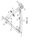
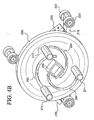
- FIGs. 4A and 4B Another embodiment of the invention is shown in Figs. 4A and 4B.
- This spacer device is characterized by lower extensibility of the effective perimeter radius, for example, from about 1 to 2% of the arm lengths.
- wheels, metering rollers or ball bearings for rolling within a hollow cylindrical measuring surface at the end of the arms, in this case the arms 210, 220, 230.
- Fig. 4 A only measuring rollers 222, 223 are shown; corresponding additional measuring rollers are provided at points A and C.
- the arms 210, 220, 230 are hinged against each other with hinges 240, 250, 260.
- arm 230 may be provided with slots or slots such that by means of a combination of one or more screws 262 and wing nuts or the like. 264 the effective side length of the spacer device can be adjusted to some extent. In confined spaces, a correspondingly effective locking device can also be operated from the side of the three-armed arrangement.
- Bolts 270, 272 and others are used for receiving and clamping (for example, also by means of wing nuts, not shown) of an Instrumenträgers.
- light emitters preferably in the form of green-emitting, in the axial direction of the hollow cylinder to be measured radiating laser beam devices, or two-dimensionally sensing Light receiving devices are arranged.
- the instrument carrier is equipped with electronic Inclinometem, so that a rotational position of the spacer device can be sensed within the hollow cylinder.
- the measured value of such Inclinometer can be converted by means of a correction function on the actual rotation angle of the instrument carrier relative to the axis of the hollow cylinder to be measured.
- FIG. 4 B where in addition to the equipped with Meßrädem- or rollers arms 210, 220, 230, an instrument carrier 280, here shown for example in the form of a circular disc.
- the instrument carrier 280 spirally arranged slots or slots 282, 284, 288, through which said bolts 270, 272, etc. are inserted.
- the bolts, including the arms 210, etc. can then be stably fixed relative to the instrument carrier 280 by means of the clamping nuts 271, 273 and 274.
- Fig. 4B is further shown how an optical element, such as a reflective prism 290 (English: right angle prism) centric on the instrument carrier 280 fixed, but interchangeable, is attached.
- an optical element such as a reflective prism 290 (English: right angle prism) centric on the instrument carrier 280 fixed, but interchangeable, is attached.
- a device which relates to a modification of the arrangement shown in FIGS. 4A and 4B.
- this modification only two arms 210 and 230 are provided which, as in FIG. 4, are provided with a hinge or the like. 240 hingedly connected.
- at positions A and C and at the other end of the arm 210 are corresponding precision rollers 222, 223, but preferably not necessarily in pairs.
- fastening elements similar to 270, 272 from FIG. 4 are provided, to which one or more preferably flat instrument carriers can be fastened, which are particularly suitable for functioning as an adapter for a light beam transmitter.
- one or more components is provided with resilient effect.
- This component or spring acts on the arms 210, 230 extending, so that always the best possible contact of the precision rollers to the Hollow cylinder is present. In this way, the measurement of hollow cylinders with variable cross-sectional area or incomplete round cross section is possible. It is advantageous that the component with resilient action in the vicinity of the hinge or the like. 240 to place. In addition, there are further attachment options for such a component with resilient effect, for example, the attachment of an end to at least one intended instrument carrier. The other end of the spring can then act on one or both arms 210, 230. This component with resilient action (spring) is thus suitable to exert on the arms (210, 230) a spreading force. As a result, contact the arms of the device according to the invention by means of precision rollers virtually backlash the surface to be measured, even in those places where their shape deviates from an ideal form.
- a preferred embodiment of the invention is shown, in the contracted or in the expanded state.
- the arms 10, 20 and 30 produced from a suitable extruded aluminum profile and the measuring rollers 27, 29 correspond to those of FIG. 1.
- the instrument carrier 50 is provided with oblong holes 51, 53, 55 which interact with locking screws 52, 54 and 56 Also, a fixation of the arms 10, 20, 30 cause relative to each other -
- rollers in the form of ball bearings similar to those provided in Fig. 2, however, the slot shown in Fig. 2 for web-like brackets now per arm is in duplicate, namely on both sides on the side surfaces of the arms 10, 20, 30th
Landscapes
- Physics & Mathematics (AREA)
- General Physics & Mathematics (AREA)
- Length Measuring Devices By Optical Means (AREA)
Applications Claiming Priority (1)
| Application Number | Priority Date | Filing Date | Title |
|---|---|---|---|
| DE102005017053 | 2005-04-12 |
Publications (2)
| Publication Number | Publication Date |
|---|---|
| EP1712876A2 true EP1712876A2 (fr) | 2006-10-18 |
| EP1712876A3 EP1712876A3 (fr) | 2008-07-09 |
Family
ID=36613386
Family Applications (1)
| Application Number | Title | Priority Date | Filing Date |
|---|---|---|---|
| EP06006514A Withdrawn EP1712876A3 (fr) | 2005-04-12 | 2006-03-29 | Dispositif extensible pour la mesure de distance |
Country Status (2)
| Country | Link |
|---|---|
| US (1) | US7350309B2 (fr) |
| EP (1) | EP1712876A3 (fr) |
Families Citing this family (4)
| Publication number | Priority date | Publication date | Assignee | Title |
|---|---|---|---|---|
| US8011110B2 (en) * | 2008-09-04 | 2011-09-06 | Mitsubishi Heavy Industries, Ltd. | Centering mechanism |
| US8118293B1 (en) * | 2009-03-18 | 2012-02-21 | The United States Of America As Represented By The Secretary Of The Navy | Multi-axis cylinder manipulator |
| US20170016707A1 (en) * | 2015-07-14 | 2017-01-19 | World Concepts Llc | Thread Gauge and Method |
| CN116858114A (zh) * | 2023-06-21 | 2023-10-10 | 煤科(北京)检测技术有限公司 | 液压支架立柱挠度及缸筒扩径量测量装置 |
Citations (2)
| Publication number | Priority date | Publication date | Assignee | Title |
|---|---|---|---|---|
| EP0543971A1 (fr) | 1991-06-13 | 1993-06-02 | Busch Dieter & Co Prueftech | Procede et dispositif de determination de la ligne mediane d'une courbure. |
| EP1083402A1 (fr) | 1999-09-10 | 2001-03-14 | Prüftechnik Dieter Busch Ag | Dispositif pour mésurer la position de l'axe d'un cylindre creux |
Family Cites Families (23)
| Publication number | Priority date | Publication date | Assignee | Title |
|---|---|---|---|---|
| US1403156A (en) * | 1920-07-06 | 1922-01-10 | Gonzalez Ramon | Boiler-diagramming apparatus |
| US2304045A (en) * | 1941-02-20 | 1942-12-01 | Crane Co | Bore reflectoscope |
| US2325362A (en) * | 1942-05-14 | 1943-07-27 | Sr Frank J Black | Apparatus for gauging dimensions of circular workpieces |
| US2485325A (en) * | 1946-05-07 | 1949-10-18 | Sloane Irving | Collapsible tripod dolly |
| US2478609A (en) * | 1946-06-29 | 1949-08-09 | Bell & Howell Co | Device for testing the eccentricity of optical elements |
| US2464070A (en) * | 1946-10-15 | 1949-03-08 | Victor J Carcelli | Self-centering bore gauge |
| US2607012A (en) * | 1950-06-10 | 1952-08-12 | Crane Co | Radiographic inspection device |
| US3907435A (en) * | 1972-09-29 | 1975-09-23 | Laser Alignment | Light beam alignment target and method |
| US3984627A (en) * | 1974-04-18 | 1976-10-05 | Andre Galerne | Method and apparatus for examining the interior of a bore hole and/or caisson or the like |
| DE3419683A1 (de) * | 1984-05-24 | 1985-11-28 | Mannesmann AG, 4000 Düsseldorf | Rohrmolch mit fahrwerken |
| US4843896A (en) * | 1988-02-26 | 1989-07-04 | Western Stress, Inc. | Probe for internal bore inspection |
| US4878296A (en) * | 1988-04-22 | 1989-11-07 | The United States Of America As Represented By The Secretary Of The Navy | Apparatus and method for locating the axis of symmetry (center of circular cross section) of three dimensional objects |
| US4872267A (en) * | 1988-06-27 | 1989-10-10 | Randy Anderton | Measuring device |
| US5074051A (en) * | 1990-07-20 | 1991-12-24 | The Boeing Company | Instrument for measuring the distance of a flange to a hole |
| US5461793A (en) * | 1993-03-31 | 1995-10-31 | Melville; Kenneth B. | Self centering pipe axis laser guide |
| US5426507A (en) * | 1993-04-19 | 1995-06-20 | Spectra-Physics Laserplane, Inc. | Laser-based pipe alignment device and method |
| US5565633A (en) * | 1993-07-30 | 1996-10-15 | Wernicke; Timothy K. | Spiral tractor apparatus and method |
| US5732474A (en) * | 1996-06-20 | 1998-03-31 | Cannon; Peggy | Visual aid and manipulative for demonstrating geometric and trigonmetric functions |
| US6237501B1 (en) * | 2000-02-28 | 2001-05-29 | Daimlerchrysler Corporation | Three-point suspension system for mounting a tool to a rail system |
| US6931748B2 (en) * | 2002-04-05 | 2005-08-23 | Varco I/P, Inc. | Riser and tubular inspection systems |
| USD514612S1 (en) * | 2003-08-13 | 2006-02-07 | Vogel's Holdin B.V. | Projector stand |
| US6996914B1 (en) * | 2004-08-09 | 2006-02-14 | Project Consulting Services, Inc. | Method and apparatus for best fitting two or more items |
| ATE420337T1 (de) * | 2005-03-04 | 2009-01-15 | Busch Dieter & Co Prueftech | Verfahren zum ausrichten von maschinen oder maschinenteilen |
-
2006
- 2006-03-29 EP EP06006514A patent/EP1712876A3/fr not_active Withdrawn
- 2006-04-12 US US11/279,422 patent/US7350309B2/en not_active Expired - Fee Related
Patent Citations (2)
| Publication number | Priority date | Publication date | Assignee | Title |
|---|---|---|---|---|
| EP0543971A1 (fr) | 1991-06-13 | 1993-06-02 | Busch Dieter & Co Prueftech | Procede et dispositif de determination de la ligne mediane d'une courbure. |
| EP1083402A1 (fr) | 1999-09-10 | 2001-03-14 | Prüftechnik Dieter Busch Ag | Dispositif pour mésurer la position de l'axe d'un cylindre creux |
Also Published As
| Publication number | Publication date |
|---|---|
| EP1712876A3 (fr) | 2008-07-09 |
| US20060225294A1 (en) | 2006-10-12 |
| US7350309B2 (en) | 2008-04-01 |
Similar Documents
| Publication | Publication Date | Title |
|---|---|---|
| EP1058809A1 (fr) | Dispositif pour fixer un dispositif de mesure d'alignement des roues sur une jante d'une roue d'un vehicule a moteur | |
| EP2215397A1 (fr) | Tête de trépied | |
| DE10312935B4 (de) | Stützbock | |
| DE202018105381U1 (de) | Koppelungsvorrichtung für Lineale | |
| DE102011014835B4 (de) | Vorrichtung zum Verstellen einer Steuerfläche eines Fluggerätemodells, Steuerflächeneinheit, Fluggerätemodell und Verwendung eines Fluggerätemodells | |
| DE10127515A1 (de) | Schaltgriff | |
| EP1712876A2 (fr) | Dispositif extensible pour la mesure de distance | |
| DE102013022018B3 (de) | Optisches Messsystem | |
| DE20017862U1 (de) | Führungsvorrichtung für eine Werkzeugmaschine | |
| DE102017128322A1 (de) | Winkelverstellbare Konsole | |
| DE2649211C3 (de) | Vorrichtung zum Ausrichten eines Spiegels für ein Laser-Nivettierungsgerat | |
| EP0611336A1 (fr) | Perforatrice avec unites de perforation reglables | |
| CH676025A5 (fr) | ||
| EP1814353B1 (fr) | Dispositif de chargement inclinable d'une enceinte acoustique | |
| DE4025392C1 (fr) | ||
| DE102006005591A1 (de) | Extendierbare Distanzvorrichtung | |
| DE19700478C2 (de) | Befestigungsvorrichtung | |
| DE102009039591A1 (de) | Haltevorrichtung und Halterung | |
| DE29706838U1 (de) | Halterung für Gegenstände in Fahrzeugen | |
| DE102006044024B3 (de) | Verlängerungselement für Spannratschen | |
| DE102015102864A1 (de) | Trägerelement einer Halterungsvorrichtung zur Aufnahme eines zu vermessenden Bauteils in einer Referenzposition | |
| DE4134094C2 (fr) | ||
| DE102009019502A1 (de) | Sensor oder Sensorhalter und Verwendung eines Sensors oder Sensorhalters | |
| DE202005006200U1 (de) | Vorrichtung zum Einstellen eines Federdämpferbeines | |
| EP1314516B1 (fr) | Elément de fixation |
Legal Events
| Date | Code | Title | Description |
|---|---|---|---|
| PUAI | Public reference made under article 153(3) epc to a published international application that has entered the european phase |
Free format text: ORIGINAL CODE: 0009012 |
|
| AK | Designated contracting states |
Kind code of ref document: A2 Designated state(s): AT BE BG CH CY CZ DE DK EE ES FI FR GB GR HU IE IS IT LI LT LU LV MC NL PL PT RO SE SI SK TR |
|
| AX | Request for extension of the european patent |
Extension state: AL BA HR MK YU |
|
| PUAL | Search report despatched |
Free format text: ORIGINAL CODE: 0009013 |
|
| AK | Designated contracting states |
Kind code of ref document: A3 Designated state(s): AT BE BG CH CY CZ DE DK EE ES FI FR GB GR HU IE IS IT LI LT LU LV MC NL PL PT RO SE SI SK TR |
|
| AX | Request for extension of the european patent |
Extension state: AL BA HR MK YU |
|
| RIC1 | Information provided on ipc code assigned before grant |
Ipc: G01B 11/27 20060101ALI20080605BHEP Ipc: G01B 21/14 20060101AFI20060710BHEP |
|
| 17P | Request for examination filed |
Effective date: 20090102 |
|
| 17Q | First examination report despatched |
Effective date: 20090213 |
|
| AKX | Designation fees paid |
Designated state(s): AT BE BG CH CY CZ DE DK EE ES FI FR GB GR HU IE IS IT LI LT LU LV MC NL PL PT RO SE SI SK TR |
|
| GRAP | Despatch of communication of intention to grant a patent |
Free format text: ORIGINAL CODE: EPIDOSNIGR1 |
|
| INTG | Intention to grant announced |
Effective date: 20150611 |
|
| STAA | Information on the status of an ep patent application or granted ep patent |
Free format text: STATUS: THE APPLICATION IS DEEMED TO BE WITHDRAWN |
|
| 18D | Application deemed to be withdrawn |
Effective date: 20151022 |