EP1712877A1 - Vorrichtung zur Schätzung von Entfernungen, Fehlererkennungvorrichtung, Temperaturregler und Wärmebehandlungsvorrichtung - Google Patents
Vorrichtung zur Schätzung von Entfernungen, Fehlererkennungvorrichtung, Temperaturregler und Wärmebehandlungsvorrichtung Download PDFInfo
- Publication number
- EP1712877A1 EP1712877A1 EP06007321A EP06007321A EP1712877A1 EP 1712877 A1 EP1712877 A1 EP 1712877A1 EP 06007321 A EP06007321 A EP 06007321A EP 06007321 A EP06007321 A EP 06007321A EP 1712877 A1 EP1712877 A1 EP 1712877A1
- Authority
- EP
- European Patent Office
- Prior art keywords
- temperature
- thermal treatment
- distance
- treated
- hot plate
- Prior art date
- Legal status (The legal status is an assumption and is not a legal conclusion. Google has not performed a legal analysis and makes no representation as to the accuracy of the status listed.)
- Granted
Links
Images





Classifications
-
- C—CHEMISTRY; METALLURGY
- C03—GLASS; MINERAL OR SLAG WOOL
- C03B—MANUFACTURE, SHAPING, OR SUPPLEMENTARY PROCESSES
- C03B29/00—Reheating glass products for softening or fusing their surfaces; Fire-polishing; Fusing of margins
- C03B29/02—Reheating glass products for softening or fusing their surfaces; Fire-polishing; Fusing of margins in a discontinuous way
- C03B29/025—Glass sheets
-
- G—PHYSICS
- G01—MEASURING; TESTING
- G01B—MEASURING LENGTH, THICKNESS OR SIMILAR LINEAR DIMENSIONS; MEASURING ANGLES; MEASURING AREAS; MEASURING IRREGULARITIES OF SURFACES OR CONTOURS
- G01B21/00—Measuring arrangements or details thereof, where the measuring technique is not covered by the other groups of this subclass, unspecified or not relevant
- G01B21/02—Measuring arrangements or details thereof, where the measuring technique is not covered by the other groups of this subclass, unspecified or not relevant for measuring length, width, or thickness
- G01B21/08—Measuring arrangements or details thereof, where the measuring technique is not covered by the other groups of this subclass, unspecified or not relevant for measuring length, width, or thickness for measuring thickness
- G01B21/085—Measuring arrangements or details thereof, where the measuring technique is not covered by the other groups of this subclass, unspecified or not relevant for measuring length, width, or thickness for measuring thickness using thermal means
-
- H—ELECTRICITY
- H10—SEMICONDUCTOR DEVICES; ELECTRIC SOLID-STATE DEVICES NOT OTHERWISE PROVIDED FOR
- H10P—GENERIC PROCESSES OR APPARATUS FOR THE MANUFACTURE OR TREATMENT OF DEVICES COVERED BY CLASS H10
- H10P95/00—Generic processes or apparatus for manufacture or treatments not covered by the other groups of this subclass
Definitions
- the present invention relates to a distance estimation apparatus for estimating a distance between an object to be treated and a thermal treatment means in thermal treatment such as heating treatment and cooling treatment, and an abnormality detection apparatus, a temperature regulator and a thermal treatment apparatus, for which the distance estimation apparatus is used.
- a work such as a glass substrate is placed with respect to a hot plate having been heated to a set temperature, and then thermally treated for a predetermined period of time (e.g. Japanese Patent Application Laid-Open No. 2004-134723 ).
- thermal treatment for example in a case where a foreign substance or the like intervenes between the work and the hot plate or the work has been transformed, namely, in a case where a distance between the work and the hot plate is not normal, thermal treatment becomes incomplete, which might lead to generation of a large number of defective products incompletely thermally treated in such a manufacturing process as a process for thermally treating a large number of works in sequence.
- a primary object of the present invention is enabling estimation of a distance between an object to be treated such as a work and a thermal treatment means such as a hot plate. Another object is enabling detection of abnormality of thermal treatment.
- the present invention is configured as follows.
- the distance estimation apparatus of the present invention is an apparatus for estimating a distance between an object to be treated and a thermal treatment means in thermal treatment on the object to be treated with the thermal treatment means, comprising a distance estimation means of estimating the distance based upon information on a temperature of at least either of the object to be treated or the thermal treatment means.
- the thermal treatment means refers to a means of thermally treating an object to be treated, such as a hot plate, a thermal treatment furnace, a successive furnace, and a thermocompressing part of a wrapping machine.
- the thermal treatment is not restricted to heating treatment, and may also be cooling treatment or heating/cooling treatment.
- the thermal treatment may be thermal treatment on the entire object to be treated, or thermal treatment only on part of the object to be treated, such as the surface of the object to be treated.
- the estimated distance is preferably a distance between the facing portions of the object to be treated and the thermal treatment means.
- the thermal treatment is preferably performed by bringing the object to be treated close to the thermal treatment means, it may also be performed by bringing the thermal treatment into contact with or attached to the thermal treatment means. In such a case, it is preferable to estimate a distance between portions of the object to be treated and the thermal treatment means, the portions being neither in contact with or attached to each other.
- part of the object to be treated may be in contact with the thermal treatment means.
- the object to be treated may be shifted toward the thermal treatment means, the thermal treatment means may be shifted toward the object to be treated, or both of them may be shifted.
- the present invention it is possible to estimate the distance between the object to be treated and the thermal treatment means based upon either piece of temperature information of the object to be treated and the thermal treatment means which change according to the distance.
- the temperature information includes information on a temperature change after the object to be treated has been brought close to the thermal treatment means, and the larger the temperature change is, the smaller the distance estimation means estimates the distance to be.
- the temperature information may include information before the object to be treated is brought close to the thermal treatment means.
- the temperature change information be inclination of the temperature change.
- the temperature information includes information on a change in difference in temperature between the thermal treatment means and the object to be treated after the object to be treated has been brought close to the thermal treatment means, and the larger the change in temperature difference is, the smaller the distance estimation means estimates the distance to be.
- the distance estimation means estimates the distance based upon information on an operating amount of a temperature control means of controlling the temperature of the thermal treatment means in addition to at least either piece of the temperature information.
- this operating amount information be information on an operating amount of the temperature control means after the object to be treated has been brought close to the thermal treatment means, and the larger the operating amount is, the smaller the distance estimation means estimates the distance to be.
- the distance is estimated based upon information on the operating amount in addition to the temperature information, and it is thereby possible to estimate the distance with high accuracy.
- the distance estimation means comprises: a first estimation part for estimating thermal resistance between an object to be treated and a thermal treatment means; and a second estimation part for estimating the distance based upon the estimated thermal resistance.
- thermal resistance be estimated based upon the operating amount information and the temperature information in the first estimation part, and the first estimation part comprise a model of the object to be treated which estimates the temperature of the object to be treated based upon the temperature information.
- each piece of the information for use in estimation of the distance in the distance estimation means is information during part of a period when the temperature of the thermal treatment means returns to a constant temperature, after the object to be treated has been brought close to the thermal treatment means.
- the thermal treatment means is a hot plate with respect to which the object to be treated is placed and then thermally treated.
- the object to be treated is preferably a glass substrate or the like which is placed with respect to the hot plate and then thermally treated.
- the distance estimation means is preferably provided with a signal indicating timing in which the object that is placed with respect to the hot plate and then thermally treated is brought close to the hot plate.
- the distance between the hot plate and the object to be treated such as the glass substrate is estimated, in a case where the object to be treated is not placed in a regular position of the hot plate, or a foreign substance or the like intervenes between the hot plate and the object to be treated and the object to be treated is then displaced from the normal distance, such positional irregularity or displacement can be detected.
- the distance estimation means estimates respective distances between a plurality of points of the thermal treatment means and a plurality of corresponding points of the object to be treated.
- the distances between the plurality of points are estimated, it is possible for example to grasp the shape and deformation of the object to be treated, a positional relation of the object to be treated with respect to the thermal treatment face based upon the distances to the plurality of points with the thermal treatment face of the thermal treatment means taken as reference.
- An abnormality detection apparatus of the present invention comprises: the distance estimation apparatus according to the present invention; and a determination means of determining the presence or absence of abnormality of the thermal treatment by comparison of a distance estimated by the distance estimation apparatus and a threshold.
- the threshold is preferably one which corresponds to a normal distance range.
- comparison between the estimated distance and the threshold allows determination as to whether the thermal treatment is performed at a normal distance or not, and it is thereby possible to detect the presence or absence of abnormality of the thermal treatment.
- the abnormality detection apparatus of the present invention comprises: the distance estimation apparatus according to the present invention; and a determination means of determining the state of the object to be treated based upon the distances between a plurality of points which are estimated by the distance estimation apparatus, wherein abnormality is detected based upon output of the determination means.
- the state of the object to be treated refers to the arranged state of the object to be treated with respect to the thermal treatment means, such as inclination of the object to be treated, the state of shape of the object to be treated, e.g. the state of deformation such as warping of the object to be treated, and some other states.
- the state of the object to be treated is determined based upon the distances between the plurality of the points, it is possible to detect abnormality of thermal treatment for example in a state where the object to be treated runs on a foreign subject or the like, or is deformed.
- a temperature regulator of the present invention comprises the distance estimation apparatus according to the present invention, and controls a temperature of the thermal treatment means.
- the temperature information of the thermal treatment means is given and also the temperature regulator itself which outputs operating amount information can estimate the distance.
- the temperature of the thermal treatment means is controlled such that a temperature detected by a temperature detection means of detecting a temperature of the thermal treatment means is a set temperature.
- the temperature regulator comprises a correction means of correcting at least either of the set temperature or the detected temperature based upon the distance estimated by the distance estimation apparatus.
- the correction means preferably makes correction so as to make the degree of thermal treatment stronger with a larger estimated distance.
- the temperature regulator of the present invention comprises the abnormality detection apparatus according to the present invention, wherein the temperature of the thermal treatment means is controlled.
- the thermal treatment apparatus of the present invention comprises: the temperature regulator according to the present invention; the thermal treatment means; an operation means of heating and/or cooling the thermal treatment means based upon output of the temperature regulator; and a temperature detection means of detecting the temperature of the thermal treatment means.
- the thermal treatment apparatus capable of detecting abnormality of thermal treatment.
- the distance between the object to be treated and the thermal treatment means can be estimated based upon temperature information of at least one of the object to be treated and the thermal treatment means, it is possible to determine whether the distance is normal or not to detect abnormality of thermal treatment, or to grasp the shape and the arranged state of the object to be treated.
- Fig. 1 shows a schematic constitutional view of a thermal treatment apparatus according to one embodiment of the present invention.
- the temperature of the hot plate 1 where the work is thermally treated is detected with a temperature sensor provided inside the hot plate 1, and then inputted into a temperature regulator 2 according to the present invention.
- a PID calculation or the like is performed with a PID controller 3 as the temperature control means based upon a deviation of a target temperature (set temperature) SP having been set and a detected temperature PV, to output an operating amount for controlling passage of a current of a heater (not shown) arranged on the hot plate 1 via an electromagnetic switch (not shown) or the like such that the temperature of the hot plate 1 is the target temperature SP.
- each work 4 to be thermally treated with the hot plate 1 is automatically placed with respect to the hot plate 1 by a conveyance supply means (not shown), and thermally treated in sequence.
- part of the work 4 such as a glass substrate is placed in the state apart from the hot plate 1 by a constant distance d by being supported by a supporting part (not shown).
- This embodiment is configured as follows. A distance d between the hot plate 1 and the work 4 when placed with respect to the hot plate 1 to be thermally treated is estimated as described later, and it is determined whether the distance is normal or not based upon the estimated distance d. When the distance between the work 4 and the hot plate 1 is abnormal, for example when the distance is larger than the normal distance and the thermal treatment is thus incomplete, such abnormality can be detected.
- the temperature regulator 2 houses an abnormality detection apparatus 6 which estimates the distance between the work 4 and the hot plate 1 based upon the temperature PV of the hot plate 1 after placement of the work 4 with respect to the hot plate 1 to determine whether the estimated distance is within a normal range or not and to detect abnormality of thermal treatment.
- the abnormality detection apparatus 6 of this embodiment comprises: a distance estimation means 7 for estimating the distance between the work 4 and the hot plate 1 based upon inclination of temperature of the hot plate 1; and a detection means 8 for detecting whether the thermal treatment is normal or not based upon the estimated distance d.
- the distance estimation means 7 is provided with a timing signal corresponding to timing in which the work 4 is placed with respect to the hot plate 1, from a host apparatus for controlling throughout thermal treatment as described later, while also provided with later-described setting information t1, A, etc., which is set by the user and required for distance estimation.
- the PID controller 3, the abnormality detection apparatus 6 and the like are configured for example by a microcomputer.
- the object to be treated is the work 4, and the thermal treatment means is the hot plate 1.
- the thermal treatment means is the hot plate 1.
- the distance between the work 4 and the hot plate 1 is d
- the temperature of the work 4 is Tw
- the temperature of the hot plate 1 is Th
- a heat capacity of the work 4 is Cw
- a heat capacity of the hot plate 1 is Ch
- thermal resistance therebetween is Rhw.
- Rate ⁇ Th of temperature change of the hot plate 1 is the temperature inclination of the hot plate 1, and this temperature inclination of the hot plate 1 is measured to estimate the distance d between the work 4 and the hot plate 1 by means of a previously obtained constant k.
- Fig. 4 is a view showing how the temperature of the hot plate 1 changes with the distance between the work 4 and the hot plate 1, and also showing a temperature change of the hot plate 1 when the work 4 is placed with respect to the hot plate 1 in the state of having been heated to be adjusted to a target temperature SP with a distance therebetween excessively large (dashed line), normal (solid line) and excessively small (broken line).
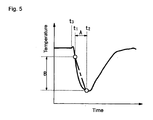
- a temperature at a first time point t1 after the work 4 has been placed with respect to the hot plate 1 and thermal treatment has been started, and a temperature at a second time point t2 when a given period of time lapses from the first time point t1 are separately measured, to calculate a temperature change width B of the hot plate 1 with respect to the constant time width A, namely the inclination of temperature of the hot plate 1 ( B/A).
- the point at which the temperature of the hot plate 1 is measured is preferably near a point from which the distance is wished to be measured, and is preferably in a portion where an influence by shift of heat due to approach of the work 4 is apt to appear. Namely, the point at which the temperature is measured is preferably in the vicinity of the surface of the side closer to the work 4. Further, the point is preferably far apart from a heater and a heat source which might cause a disturbance.
- the number of points, from which a distance is estimated may be one or more than one.
- the distance d is estimated according to the foregoing expression (a).
- the temperature regulator 2 shown in Fig. 1 is configured such that a timing signal corresponding to timing in which the work 4 is placed with respect to the hot plate 1, from a higher-level apparatus for controlling throughout thermal treatment.
- This timing signal corresponds, for example, to a timing point t3 shown in Fig. 5.
- the work 4 is placed with respect to the hot plate 1 to be thermally treated such that the distance between the work 4 and the hot plate 1 is a known normal distance, and the temperature of the hot plate 1 is measured.
- the first time point t1 and the constant time width A are set into the temperature regulator 2 with the foregoing time point t3 of the timing signal of Fig. 5 as a reference, and the known distance is set into the temperature regulator 2.
- the distance estimation means 7 of the temperature regulator 2 calculates an inclination of the measured temperature of the hot plate 1 based upon the set first time point t1 and the constant time width A, and further calculates the foregoing constant k by use of the set known distance.
- the distance estimation means 7 estimates the distance between the work 4 and the hot plate 1 according to the foregoing expression (a), and the determination means 8 determines whether the distance is within a normal range or not by comparison with a threshold which corresponds to the normal range.
- a detection signal indicating abnormality of thermal treatment is outputted, for example, to a higher-level apparatus so that the higher-level apparatus can take an appropriate measure such as notifying abnormality of thermal treatment or halting thermal treatment.
- Fig. 6 shows a schematic constitutional view of the thermal treatment device according to another embodiment of the present invention. Portions corresponding to those in Fig. 1 described above are provided with the same reference numerals as in Fig. 1
- the distance between the work 4 and the hot plate 1 is estimated based upon the temperature inclination of the hot plate 1.
- the distance between the work 4 and the hot plate 1 is estimated based upon the temperature of the hot plate 1 and an operating amount U obtained from the PID controller 3.
- the distance between the work 4 and the hot plate 1 is d
- the temperature of the work 4 is Tw
- the temperature of the hot plate 1 is Th
- a heat capacity of the work 4 is Cw
- a heat capacity of the hot plate 1 is Ch
- thermal resistance therebetween is Rhw
- electric power to be supplied to the heater of the hot plate 1 is W.
- the heat amount of the hot plate 1 is expressed by the following expression.
- Heat amount of hot plate Initial value of heat amount of hot plate + ⁇ 0 t amount of heat shifted to work + ⁇ 0 t heat value d t of heater Further,
- Hot plate capacity C h ⁇ Hot plate temperature T h Initial value of heat amount of hot plate + ⁇ 0 t ( temperature difference / thermal resistance ) d t + ⁇ 0 t heat value d t of heater
- T h Initial value of heat amount of hot plate + ⁇ 0 t ( temperature difference / thermal resistance ) d t + ⁇ 0 t heat value d t of heater
- ⁇ T h d T h / d t ⁇ ⁇ T h ( n ) ⁇ T h ( n ⁇ 1 ) ⁇ / ⁇ t ,
- ⁇ t sampling time.
- thermal treatment is performed in a state where the distance between the work 4 and the hot plate 1 has been set to a known distance, and using the temperature Tw of the work 4, the temperature Th of the hot plate 1 and the operating amount U in that state, it is possible to obtain the constant k2.
- each work 4 is placed with respect to the hot plate 1 to be thermally treated in sequence, and it is not easy to detect the temperature of every work 4 to be thermally treated.
- the temperature Tw of the work 4 is estimated by use of a temperature model of the work 4.
- a distance estimation means 7a of Fig. 6 estimates a work temperature Tw by the following expression, based upon the distance d calculated by the foregoing expression (3) and the temperature Th of the hot plate.
- T w ( n ) k 3 ⁇ T w ( n ⁇ 1 ) + k 4 ⁇ ⁇ ( T h ( n ⁇ 1 ) ⁇ T w ( n ⁇ 1 ) ) / d ⁇
- Tw(n) of the work in the present sampling is estimated using a temperature Tw(n-1) of the work in the last sampling, a temperature Th(n-1) of the hot plate 1 in the last sampling and a distance d estimated in the last sampling.
- the constants k3 and k4 can be previously determined by measurement of the temperature Tw of the work 4 and the temperature Th of the hot plate 1 in thermal treatment with a known distance d.
- the distance estimation means 7a of a temperature regulator 2a based upon the temperature of the hot plate 1, the temperature of the work estimated based upon the temperature of the hot plate 1, and the operating amount U, the distance is estimated according to the foregoing expression (3).
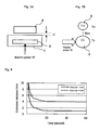
- Fig. 8 shows one example of data of distance estimation according to this embodiment.
- Fig. 8 shows changes in estimated distance between the work 4 and the hot plate 1 when the distance is set to 1 mm and 4 mm, respectively. As the work 4 is brought closer to the hot plate 1 with the passage of time, the respective estimated distances become smaller, and then are kept constant at 1 mm and 4mm.
- the distance is estimated based upon the temperature and the operating amount of the hot plate 1, as another embodiment of the present invention, the distance may be estimated based upon the temperature of the hot plate 1, the temperature of the work 4 and the operating amount.
- Fig. 9 shows a schematic constitutional view of the thermal treatment apparatus according to still another embodiment of the present invention. Portions corresponding to those in Fig. 1 described above are provided with the same reference numerals as in Fig. 1.
- the distance is estimated through the use of a model structure under control which is appropriate for decoupling control which was previously proposed by the applicant of this invention as a "model structure, control apparatus, temperature regulator and thermal treatment apparatus" in Japanese Patent Application Laid-Open No. 2004-94939 ( Japanese Patent Application No. 2003-289867 ).
- a model structure 30 under control shown in Fig. 9 comprises a model element 10 corresponding to the hot plate 1 and a model element 11 corresponding to the work 4, a difference in output (temperature difference) between the model elements 10 and 11 is fed back to the input sides of the model elements 10 and 11 with the poles thereof made different through a feedback element 12.
- This model represents in a block diagram a heat shifting phenomenon of in which a heat amount shifts from the hot plate 1 (10) to the work 4(11) due to the temperature difference between the hot plate 1(10) and the work 4(11), and the heat amount is removed from the hot plate 1(10) (negative) while the heat amount is added to the work 4(11) (positive).
- temperature difference model is equivalent to Fourier's law which states that a heat amount shifts when there is a temperature difference and the shift of the heat amount is proportional to the temperature difference.
- a 11 , A 22 are transfer functions of the model elements 10 and 11 which correspond to the hot plate 1 and the work 4, respectively.
- the feedback element 12 shows shifting of the heat amount according to the temperature difference.
- ⁇ is thermal resistance between the hot plate 1 and the work 4.
- a switch means 19 on the output side of the feedback element 12 is turned off so that the temperature difference between the work 4 and the hot plate 1 is not fed back.
- the switch means 19 is turned on and the temperature difference between the work 4 and the hot plate 1 is fed back.
- thermal resistance ⁇ between the hot plate 1 and the work 4 allows estimation of the distance d between the work 4 and the hot plate 1 based upon a thermal conductivity K of the air and a facing area S of the work 4 and the hot plate 1, using the following expression:
- the distance estimation means 7b of a temperature regulator 2d of this embodiment comprise a work model 13 for estimating a work temperature and an estimation element 14 for estimating a heat amount (heat current) through the hot plate 1 per one hour according to the temperature of the hot plate 1.
- the work model 13 comprises compensation elements 11' and 12' of transfer functions A' 22 , 1/ ⁇ ' as in the case of the model element 11 and the feedback element 12 of the temperature difference model, and further has a switch means 20 corresponding to the switch means 19. According to a timing signal from the higher-level apparatus, the work model 13 is turned on when the work 4 is placed with respect to the work 4, and turned off when thermal treatment is completed.
- this work model 13 is not required to correspond to the temperature difference model, and may be another model such as an ARX model or a transfer function model, as long as being capable of estimating the temperature of the work 4 from the temperature of the hot plate 1.
- the estimation element 14 corresponds to the model element 10 of the hot plate 1 of the temperature difference model, and an inverse number 1/A' 11 of the transfer function A 11 of the model element 10 is a transfer function.
- a temperature difference ⁇ T' between a temperature PV of the hot plate 1 and a work temperature estimated by means of the work model 13 is calculated in a subtraction part 15
- a heat current which was estimated in the estimation element 14 and flown into the hot plate 1 from a heat current generated from a heater is subtracted in a subtraction part 16 to calculate a heat current Q' that flows between the hot plate 1 and the work 4.
- the estimated temperature difference ⁇ T' is divided by the estimated heat current Q' to estimate the thermal resistance ⁇ ', and using this thermal resistance ⁇ ', the heat conductivity Ka of the air and the facing area S of the work 4 and the hot plate 1, the estimated distance d between the work 4 and the hot plate 1 is calculated in the distance estimation part 18.
- the heat current to be inputted into the subtraction part 16 from the PID controller 3 can be obtained by direct calculation when the output value of the PID controller 3 is a heat current itself, or by calculation according to the output value from the PID controller 3 when the output value is an operating amount.
- the distance estimation means 7b of this embodiment comprises: a first estimation part for estimating thermal resistance between the work 4 and the hot plate 1; and a second estimation part for estimating a distance based upon the estimated thermal resistance.
- the transfer function A 11 of the hot plate 1 is for example a primary delay system, and can be obtained for example from the maximum inclination formed by auto tuning.
- the transfer function of the work 4 is the primary delay system which includes a constant corresponding to the heat capacity of the work 4 and a constant according to the thermal resistance of the work 4, and for example, the heat capacity can be obtained from a material and a size of the work 4.
- the determination means 8 determines the presence or absence of abnormality by comparison of the estimated distance and the threshold in the foregoing embodiment, the following operation may also be performed as another embodiment of the present invention. Respective distances between a plurality of points of the work and the hot plate are separately estimated, and the shape, inclination and the like of the work are determined based upon the estimated distances between those plurality of points so as to detect abnormality.
- a distance estimation part 7c estimates respective distances between a plurality of points of the work 4 and the hot plate 1 based upon a temperature and an operating amount, as in each of the foregoing embodiments.
- a shape recognition part 21 recognizes the shape of the work based upon those plurality of estimated distances.
- a determination part 22 determines whether the recognized shape has exceeded the threshold or not, and then outputs an abnormality detection signal indicating abnormality of the shape of the work 4 when the shape has exceeded the threshold.
- the shape recognition part 21 calculates a difference (dmax - dmin) between the maximum estimated distance (dmax) and the minimum estimated distance (dmin) among the plurality of estimated distances, to recognize a flatness.
- the determination part 22 determines whether this flatness has exceeded a certain range (threshold) or not, and then outputs an abnormality detection signal indicating abnormality of the shape of the work 4 when the flatness has exceeded the threshold.
- the shape recognition part 21 calculates a difference (d1-d2) between an estimated distance d1 of the central part of the work 4 and an estimated distance d2 of the periphery, to recognize a curving degree.
- the determination part 22 determines whether this curving degree has exceeded a certain range (threshold) or not, and then outputs an abnormality detection signal indicating abnormality of the shape of the work 4 when the curving degree has exceeded the threshold.
- a foreign substance intervenes between the work 4 and the hot plate 1 and the work 4 is placed onto the work 4 to become inclined, the shape of the work 4 might be improperly detected as abnormal although it is normal.
- a plurality of points for distance estimation are provided point-symmetrically on a concentric circle and an average value of those estimated distances is set to d2ave, whereby it is possible to cancel the inclination of the work 4 due to placement thereof onto the foreign substance by setting the foregoing curving degree to d1-d2ave.
- the difference (dmax - dmin) between the maximum estimated distance (dmax) and the minimum estimated distance (dmin) among a plurality of estimated distances may be calculated, followed by comparison with the threshold, to detect abnormality that the work 4 has placed onto the foreign substance or the like and become inclined.
- the following operation may be performed.
- a target temperature is corrected to be higher so as to increase heat application.
- a target temperature is corrected to be lower so as to decrease heat application.
- a target temperature correction part 23 may calculate a target temperature correction value ⁇ SP based upon an estimated distance estimated in the distance estimation part 7c so that the target temperature SP is corrected using the target temperature correction value ⁇ SP.
- a correction value to be calculated by the following expression can be employed.
- the reference hot plate temperature and the reference work temperature are previously obtained respond waveforms (time-series temperature data) of the hot plate and the work in a case where the distance is normal (reference distance).
- the target temperature Due to such correction of the target temperature, for example, an increase in temperature of the work 4 is delayed when the distance between the work 4 and the hot plate 1 is large. In order to make the increase faster, the target temperature is increased. It is to be noted that the detected temperature provided from the temperature sensor may be corrected in place of correction of the target temperature.
- the abnormality detection apparatus may be configured as a separate apparatus from the temperature regulator. Further, only the distance estimation means may be configured as another independent distance estimation apparatus.
- the thermal treatment surface of the thermal treatment means was flat in the foregoing embodiments, the shape of the surface is not restricted to flat, but may be arbitral, such as curved or concavo-convex, and the shape of the object to be treated may also be arbitral.
- the object to be treated such as a work is placed with respect to the thermal treatment means such as a hot plate to be thermally treated in the foregoing embodiments
- the object to be treated may be brought close to and passed through the thermal treatment means for thermal treatment, or the object to be treated may be brought into contact with the thermal treatment means for thermal treatment.
- the present invention is useful for example for detection of abnormality in thermal treatment such as thermal treatment on a work by means of a hot plate, and the like.
Landscapes
- Chemical & Material Sciences (AREA)
- Physics & Mathematics (AREA)
- General Physics & Mathematics (AREA)
- Engineering & Computer Science (AREA)
- Materials Engineering (AREA)
- Organic Chemistry (AREA)
- Exposure Of Semiconductors, Excluding Electron Or Ion Beam Exposure (AREA)
- Waste-Gas Treatment And Other Accessory Devices For Furnaces (AREA)
- Testing And Monitoring For Control Systems (AREA)
- Length Measuring Devices With Unspecified Measuring Means (AREA)
Applications Claiming Priority (1)
| Application Number | Priority Date | Filing Date | Title |
|---|---|---|---|
| JP2005113306A JP2006292535A (ja) | 2005-04-11 | 2005-04-11 | 距離推定装置、異常検出装置、温度調節器および熱処理装置 |
Publications (2)
| Publication Number | Publication Date |
|---|---|
| EP1712877A1 true EP1712877A1 (de) | 2006-10-18 |
| EP1712877B1 EP1712877B1 (de) | 2009-11-11 |
Family
ID=36615729
Family Applications (1)
| Application Number | Title | Priority Date | Filing Date |
|---|---|---|---|
| EP06007321A Expired - Lifetime EP1712877B1 (de) | 2005-04-11 | 2006-04-06 | Vorrichtung zur Schätzung von Entfernungen, Fehlererkennungvorrichtung, Temperaturregler und Wärmebehandlungsvorrichtung |
Country Status (7)
| Country | Link |
|---|---|
| US (1) | US20060249502A1 (de) |
| EP (1) | EP1712877B1 (de) |
| JP (1) | JP2006292535A (de) |
| KR (1) | KR100791199B1 (de) |
| CN (1) | CN100381784C (de) |
| DE (1) | DE602006010261D1 (de) |
| TW (1) | TWI298383B (de) |
Families Citing this family (8)
| Publication number | Priority date | Publication date | Assignee | Title |
|---|---|---|---|---|
| JP5028939B2 (ja) * | 2006-10-10 | 2012-09-19 | オムロン株式会社 | 異常検出装置、異常検出方法、温度調節器および熱処理装置 |
| US8613834B2 (en) | 2008-04-03 | 2013-12-24 | Basf Se | Paper coating or binding formulations and methods of making and using same |
| CN103290198A (zh) * | 2013-06-04 | 2013-09-11 | 无锡明珠钢球有限公司 | 一种钢球调温淬火装置 |
| CN105333726B (zh) * | 2014-06-26 | 2017-06-30 | 宁波江丰电子材料股份有限公司 | 真空热压烧结装置以及测温方法 |
| JP6874719B2 (ja) * | 2018-03-02 | 2021-05-19 | オムロン株式会社 | 加熱装置及び加熱装置の異常検知方法 |
| KR102225682B1 (ko) * | 2018-09-28 | 2021-03-12 | 세메스 주식회사 | 기판의 열처리 방법 |
| JP7807957B2 (ja) | 2022-03-24 | 2026-01-28 | 株式会社Screenホールディングス | 異常検知装置 |
| JP2024066266A (ja) * | 2022-11-01 | 2024-05-15 | オムロン株式会社 | 温調システム、異常判定方法および異常判定装置 |
Citations (3)
| Publication number | Priority date | Publication date | Assignee | Title |
|---|---|---|---|---|
| JPH04242105A (ja) * | 1991-01-14 | 1992-08-28 | Sumitomo Metal Ind Ltd | 位置計測装置 |
| DE4305498A1 (de) * | 1993-02-23 | 1994-08-25 | Loi Ind Ofenanlagen | Durchlaufofen mit Positionssensor |
| AT406423B (de) * | 1997-12-22 | 2000-05-25 | Forsch Laserbau Und Laserbearb | Sensorsystem zur erfassung von temperatur und position des schmelzbades bei der lasermaterialbearbeitung |
Family Cites Families (14)
| Publication number | Priority date | Publication date | Assignee | Title |
|---|---|---|---|---|
| JPS59220609A (ja) * | 1983-05-30 | 1984-12-12 | Nissan Motor Co Ltd | タ−ビン運転中のクリアランス測定方法 |
| JPS6154172A (ja) * | 1984-08-24 | 1986-03-18 | 株式会社日立製作所 | ブラウン管の製造方法 |
| JPH03223658A (ja) * | 1989-10-26 | 1991-10-02 | Kobe Steel Ltd | 耐火物の表面状況監視方法および耐火物の補修時期判定装置 |
| JPH04350549A (ja) * | 1991-05-27 | 1992-12-04 | Anritsu Corp | 薄膜の膜厚を測定する方法 |
| JPH10284360A (ja) * | 1997-04-02 | 1998-10-23 | Hitachi Ltd | 基板温度制御装置及び方法 |
| JPH1163968A (ja) * | 1997-08-22 | 1999-03-05 | Kawasou Denki Kogyo Kk | 鋳造用モールドの熱流束検出によるエアギャップ測定方法並びに熱流束検出装置及び同装置におけるセンサー装置 |
| JPH11316118A (ja) * | 1998-05-06 | 1999-11-16 | Nippon Steel Corp | 耐火物の厚さ推定方法 |
| US6191394B1 (en) * | 1999-05-19 | 2001-02-20 | Tokyo Electron Ltd. | Heat treating apparatus |
| JP3581303B2 (ja) * | 2000-07-31 | 2004-10-27 | 東京エレクトロン株式会社 | 判別方法及び処理装置 |
| US6623158B2 (en) * | 2001-06-15 | 2003-09-23 | International Business Machines Corporation | Method and apparatus for thermal proximity imaging using pulsed energy |
| JP3639546B2 (ja) * | 2001-07-25 | 2005-04-20 | 株式会社日立国際電気 | 基板処理装置及び半導体装置の製造方法 |
| JP2003086527A (ja) * | 2001-09-07 | 2003-03-20 | Dainippon Screen Mfg Co Ltd | 熱処理装置 |
| CN2583622Y (zh) * | 2002-11-12 | 2003-10-29 | 洛阳玻璃股份有限公司 | 浮法玻璃在线简易测板宽装置 |
| US7094994B2 (en) * | 2003-03-11 | 2006-08-22 | Sony Corporation | Heat treatment apparatus and method of semiconductor wafer |
-
2005
- 2005-04-11 JP JP2005113306A patent/JP2006292535A/ja active Pending
-
2006
- 2006-04-06 EP EP06007321A patent/EP1712877B1/de not_active Expired - Lifetime
- 2006-04-06 DE DE602006010261T patent/DE602006010261D1/de not_active Expired - Lifetime
- 2006-04-07 CN CNB2006100732861A patent/CN100381784C/zh not_active Expired - Fee Related
- 2006-04-07 US US11/399,611 patent/US20060249502A1/en not_active Abandoned
- 2006-04-10 KR KR1020060032206A patent/KR100791199B1/ko not_active Expired - Fee Related
- 2006-04-10 TW TW095112600A patent/TWI298383B/zh not_active IP Right Cessation
Patent Citations (3)
| Publication number | Priority date | Publication date | Assignee | Title |
|---|---|---|---|---|
| JPH04242105A (ja) * | 1991-01-14 | 1992-08-28 | Sumitomo Metal Ind Ltd | 位置計測装置 |
| DE4305498A1 (de) * | 1993-02-23 | 1994-08-25 | Loi Ind Ofenanlagen | Durchlaufofen mit Positionssensor |
| AT406423B (de) * | 1997-12-22 | 2000-05-25 | Forsch Laserbau Und Laserbearb | Sensorsystem zur erfassung von temperatur und position des schmelzbades bei der lasermaterialbearbeitung |
Non-Patent Citations (1)
| Title |
|---|
| PATENT ABSTRACTS OF JAPAN vol. 017, no. 014 (P - 1467) 11 January 1993 (1993-01-11) * |
Also Published As
| Publication number | Publication date |
|---|---|
| EP1712877B1 (de) | 2009-11-11 |
| US20060249502A1 (en) | 2006-11-09 |
| KR100791199B1 (ko) | 2008-01-02 |
| TW200726952A (en) | 2007-07-16 |
| JP2006292535A (ja) | 2006-10-26 |
| CN1847786A (zh) | 2006-10-18 |
| DE602006010261D1 (de) | 2009-12-24 |
| CN100381784C (zh) | 2008-04-16 |
| KR20060107924A (ko) | 2006-10-16 |
| TWI298383B (en) | 2008-07-01 |
Similar Documents
| Publication | Publication Date | Title |
|---|---|---|
| CN102117037B (zh) | 加热装置及其异常判断方法,定影装置和图像形成装置 | |
| CN107068588B (zh) | 基板处理装置和基板处理装置的调整方法 | |
| EP1712877B1 (de) | Vorrichtung zur Schätzung von Entfernungen, Fehlererkennungvorrichtung, Temperaturregler und Wärmebehandlungsvorrichtung | |
| US8812168B2 (en) | Temperature measuring method and temperature measuring device of steel plate, and temperature control method of steel plate | |
| JP6384417B2 (ja) | 通電加熱装置および通電加熱方法 | |
| JPH09145265A (ja) | 電気炉の温度制御方法および装置 | |
| KR20030076382A (ko) | 열처리 방법 및 열처리 장치 | |
| US20070116083A1 (en) | Fluid-measuring device and fluid-measuring method | |
| US20170019950A1 (en) | Electrical heating device and electrical heating method | |
| CN113591276A (zh) | 一种获取退火炉的带钢辐射系数的方法及系统 | |
| JP2519928B2 (ja) | レ−ザ加熱装置の熱量制御方法 | |
| WO2007091299A1 (ja) | Tft基板の加熱方法、tft基板の温度測定方法、およびtft基板の温度制御方法 | |
| JPS61179439A (ja) | 熱現像装置 | |
| JP2000297330A (ja) | ストリップ連続焼鈍炉の板温測定方法及びその装置 | |
| JP5028939B2 (ja) | 異常検出装置、異常検出方法、温度調節器および熱処理装置 | |
| JP5328303B2 (ja) | 光学素子の製造装置及びその製造方法 | |
| JPS6411691B2 (de) | ||
| JPH05299333A (ja) | ベーク処理装置 | |
| JP4009847B2 (ja) | 熱処理異常検知方法及び温度調節器 | |
| JP2006155169A (ja) | 温度制御方法、温度調節器および熱処理システム | |
| JPS62238328A (ja) | 加熱制御装置 | |
| JPH076842B2 (ja) | 輻射熱検知装置 | |
| JPH0534203A (ja) | 高温物体の温度測定方法 | |
| JP3204490B2 (ja) | 熱定着装置の温度制御方法 | |
| JP2858788B2 (ja) | 電気温水器の運転制御方法 |
Legal Events
| Date | Code | Title | Description |
|---|---|---|---|
| PUAI | Public reference made under article 153(3) epc to a published international application that has entered the european phase |
Free format text: ORIGINAL CODE: 0009012 |
|
| AK | Designated contracting states |
Kind code of ref document: A1 Designated state(s): AT BE BG CH CY CZ DE DK EE ES FI FR GB GR HU IE IS IT LI LT LU LV MC NL PL PT RO SE SI SK TR |
|
| AX | Request for extension of the european patent |
Extension state: AL BA HR MK YU |
|
| 17P | Request for examination filed |
Effective date: 20070417 |
|
| 17Q | First examination report despatched |
Effective date: 20070522 |
|
| AKX | Designation fees paid |
Designated state(s): DE FR GB IT |
|
| GRAP | Despatch of communication of intention to grant a patent |
Free format text: ORIGINAL CODE: EPIDOSNIGR1 |
|
| RIC1 | Information provided on ipc code assigned before grant |
Ipc: G01C 3/00 20060101ALI20090504BHEP Ipc: G01B 21/08 20060101AFI20090504BHEP |
|
| GRAJ | Information related to disapproval of communication of intention to grant by the applicant or resumption of examination proceedings by the epo deleted |
Free format text: ORIGINAL CODE: EPIDOSDIGR1 |
|
| GRAP | Despatch of communication of intention to grant a patent |
Free format text: ORIGINAL CODE: EPIDOSNIGR1 |
|
| GRAS | Grant fee paid |
Free format text: ORIGINAL CODE: EPIDOSNIGR3 |
|
| GRAA | (expected) grant |
Free format text: ORIGINAL CODE: 0009210 |
|
| RIN1 | Information on inventor provided before grant (corrected) |
Inventor name: NANNO, IKUO,OMRON CORP. Inventor name: OZAKI, FUMINORI,OMRON CORP. Inventor name: YAMADA, TAKAAKI,OMRON CORP. |
|
| AK | Designated contracting states |
Kind code of ref document: B1 Designated state(s): DE FR GB IT |
|
| REG | Reference to a national code |
Ref country code: GB Ref legal event code: FG4D |
|
| REF | Corresponds to: |
Ref document number: 602006010261 Country of ref document: DE Date of ref document: 20091224 Kind code of ref document: P |
|
| PLBE | No opposition filed within time limit |
Free format text: ORIGINAL CODE: 0009261 |
|
| STAA | Information on the status of an ep patent application or granted ep patent |
Free format text: STATUS: NO OPPOSITION FILED WITHIN TIME LIMIT |
|
| 26N | No opposition filed |
Effective date: 20100812 |
|
| PGFP | Annual fee paid to national office [announced via postgrant information from national office to epo] |
Ref country code: DE Payment date: 20120430 Year of fee payment: 7 |
|
| PGFP | Annual fee paid to national office [announced via postgrant information from national office to epo] |
Ref country code: FR Payment date: 20120420 Year of fee payment: 7 Ref country code: GB Payment date: 20120411 Year of fee payment: 7 |
|
| PGFP | Annual fee paid to national office [announced via postgrant information from national office to epo] |
Ref country code: IT Payment date: 20120418 Year of fee payment: 7 |
|
| REG | Reference to a national code |
Ref country code: DE Ref legal event code: R082 Ref document number: 602006010261 Country of ref document: DE Representative=s name: KILIAN KILIAN & PARTNER, DE |
|
| GBPC | Gb: european patent ceased through non-payment of renewal fee |
Effective date: 20130406 |
|
| PG25 | Lapsed in a contracting state [announced via postgrant information from national office to epo] |
Ref country code: GB Free format text: LAPSE BECAUSE OF NON-PAYMENT OF DUE FEES Effective date: 20130406 Ref country code: DE Free format text: LAPSE BECAUSE OF NON-PAYMENT OF DUE FEES Effective date: 20131101 |
|
| REG | Reference to a national code |
Ref country code: FR Ref legal event code: ST Effective date: 20131231 |
|
| REG | Reference to a national code |
Ref country code: DE Ref legal event code: R119 Ref document number: 602006010261 Country of ref document: DE Effective date: 20131101 |
|
| PG25 | Lapsed in a contracting state [announced via postgrant information from national office to epo] |
Ref country code: IT Free format text: LAPSE BECAUSE OF NON-PAYMENT OF DUE FEES Effective date: 20130406 Ref country code: FR Free format text: LAPSE BECAUSE OF NON-PAYMENT OF DUE FEES Effective date: 20130430 |