EP1713120A2 - Methode und Apparat zur Herstellung von Kühlkörpern hoher Lamellendichte - Google Patents
Methode und Apparat zur Herstellung von Kühlkörpern hoher Lamellendichte Download PDFInfo
- Publication number
- EP1713120A2 EP1713120A2 EP06007763A EP06007763A EP1713120A2 EP 1713120 A2 EP1713120 A2 EP 1713120A2 EP 06007763 A EP06007763 A EP 06007763A EP 06007763 A EP06007763 A EP 06007763A EP 1713120 A2 EP1713120 A2 EP 1713120A2
- Authority
- EP
- European Patent Office
- Prior art keywords
- fins
- base plates
- jaws
- base
- base plate
- Prior art date
- Legal status (The legal status is an assumption and is not a legal conclusion. Google has not performed a legal analysis and makes no representation as to the accuracy of the status listed.)
- Granted
Links
Images


Classifications
-
- H—ELECTRICITY
- H10—SEMICONDUCTOR DEVICES; ELECTRIC SOLID-STATE DEVICES NOT OTHERWISE PROVIDED FOR
- H10W—GENERIC PACKAGES, INTERCONNECTIONS, CONNECTORS OR OTHER CONSTRUCTIONAL DETAILS OF DEVICES COVERED BY CLASS H10
- H10W40/00—Arrangements for thermal protection or thermal control
- H10W40/01—Manufacture or treatment
- H10W40/03—Manufacture or treatment of arrangements for cooling
- H10W40/037—Assembling together parts thereof
-
- B—PERFORMING OPERATIONS; TRANSPORTING
- B23—MACHINE TOOLS; METAL-WORKING NOT OTHERWISE PROVIDED FOR
- B23P—METAL-WORKING NOT OTHERWISE PROVIDED FOR; COMBINED OPERATIONS; UNIVERSAL MACHINE TOOLS
- B23P2700/00—Indexing scheme relating to the articles being treated, e.g. manufactured, repaired, assembled, connected or other operations covered in the subgroups
- B23P2700/10—Heat sinks
-
- Y—GENERAL TAGGING OF NEW TECHNOLOGICAL DEVELOPMENTS; GENERAL TAGGING OF CROSS-SECTIONAL TECHNOLOGIES SPANNING OVER SEVERAL SECTIONS OF THE IPC; TECHNICAL SUBJECTS COVERED BY FORMER USPC CROSS-REFERENCE ART COLLECTIONS [XRACs] AND DIGESTS
- Y10—TECHNICAL SUBJECTS COVERED BY FORMER USPC
- Y10T—TECHNICAL SUBJECTS COVERED BY FORMER US CLASSIFICATION
- Y10T29/00—Metal working
- Y10T29/49—Method of mechanical manufacture
- Y10T29/4935—Heat exchanger or boiler making
-
- Y—GENERAL TAGGING OF NEW TECHNOLOGICAL DEVELOPMENTS; GENERAL TAGGING OF CROSS-SECTIONAL TECHNOLOGIES SPANNING OVER SEVERAL SECTIONS OF THE IPC; TECHNICAL SUBJECTS COVERED BY FORMER USPC CROSS-REFERENCE ART COLLECTIONS [XRACs] AND DIGESTS
- Y10—TECHNICAL SUBJECTS COVERED BY FORMER USPC
- Y10T—TECHNICAL SUBJECTS COVERED BY FORMER US CLASSIFICATION
- Y10T29/00—Metal working
- Y10T29/49—Method of mechanical manufacture
- Y10T29/4935—Heat exchanger or boiler making
- Y10T29/49377—Tube with heat transfer means
-
- Y—GENERAL TAGGING OF NEW TECHNOLOGICAL DEVELOPMENTS; GENERAL TAGGING OF CROSS-SECTIONAL TECHNOLOGIES SPANNING OVER SEVERAL SECTIONS OF THE IPC; TECHNICAL SUBJECTS COVERED BY FORMER USPC CROSS-REFERENCE ART COLLECTIONS [XRACs] AND DIGESTS
- Y10—TECHNICAL SUBJECTS COVERED BY FORMER USPC
- Y10T—TECHNICAL SUBJECTS COVERED BY FORMER US CLASSIFICATION
- Y10T29/00—Metal working
- Y10T29/49—Method of mechanical manufacture
- Y10T29/4935—Heat exchanger or boiler making
- Y10T29/49377—Tube with heat transfer means
- Y10T29/49378—Finned tube
- Y10T29/49384—Internally finned
-
- Y—GENERAL TAGGING OF NEW TECHNOLOGICAL DEVELOPMENTS; GENERAL TAGGING OF CROSS-SECTIONAL TECHNOLOGIES SPANNING OVER SEVERAL SECTIONS OF THE IPC; TECHNICAL SUBJECTS COVERED BY FORMER USPC CROSS-REFERENCE ART COLLECTIONS [XRACs] AND DIGESTS
- Y10—TECHNICAL SUBJECTS COVERED BY FORMER USPC
- Y10T—TECHNICAL SUBJECTS COVERED BY FORMER US CLASSIFICATION
- Y10T29/00—Metal working
- Y10T29/49—Method of mechanical manufacture
- Y10T29/49826—Assembling or joining
- Y10T29/49908—Joining by deforming
- Y10T29/49915—Overedge assembling of seated part
- Y10T29/49922—Overedge assembling of seated part by bending over projecting prongs
-
- Y—GENERAL TAGGING OF NEW TECHNOLOGICAL DEVELOPMENTS; GENERAL TAGGING OF CROSS-SECTIONAL TECHNOLOGIES SPANNING OVER SEVERAL SECTIONS OF THE IPC; TECHNICAL SUBJECTS COVERED BY FORMER USPC CROSS-REFERENCE ART COLLECTIONS [XRACs] AND DIGESTS
- Y10—TECHNICAL SUBJECTS COVERED BY FORMER USPC
- Y10T—TECHNICAL SUBJECTS COVERED BY FORMER US CLASSIFICATION
- Y10T29/00—Metal working
- Y10T29/53—Means to assemble or disassemble
- Y10T29/53113—Heat exchanger
- Y10T29/53122—Heat exchanger including deforming means
Definitions
- This invention relates in general to the manufacture of heatsinks, and more specifically to a method for coupling fins in a high fin-density heatsink to dual heat-dissipating base plates.
- Heatsinks are known in the art for receiving and then dissipating heat generated by electronic circuits in modern devices.
- Such well known heatsinks typically comprise one base unit to which the heat generating electronic devices are mounted, and a plurality of fins projecting from the base unit for dissipating the generated heat. It is a challenge to maximize the surface area of the fins in order to provide optimum heat transfer from the heat sink to the surrounding atmosphere while ensuring good thermal contact between the base unit and the fins.
- Heatsinks fabricated by metal extrusion have been proposed, wherein the fins and the base units are of integral construction and thereby have the optimum thermal contact.
- U.S. Patent No. 5,406,698 Lipinksi
- various methods of manufacturing whereby the fins are extruded separately from the base unit, and subsequently coupled using various methods.
- USP 5,771,966 discloses a folded heat conducting member or fin with at least one annealed metal insert having a predetermined thickness corresponding to a distance between the first and second heat conductive portions of the fin and a predetermined thickness corresponding to a depth of the groove in the base plate so that the annealed metal insert conforms to the shape of the groove when deformed to secure the base portion engaging region of the folded heat conducting member into the groove.
- the Jacoby patent proposes an impacting die to perform a deforming or swaging function to deform the fin while in the groove so that it is not removable.
- United States Patent No. 6,263,956 to Tang et al. sets forth a heat dissipating structure and method of manufacture where each slot in the base has a width slightly less than a thickness of an inserting portion of the associated heat dissipating fin, so that it will allow the heat dissipating fin to tightly insert therein.
- a fixing frame is then moulded into place for securing the fins.
- the fixing frame is formed by introducing a melt fixing material inside of fixing recesses and thereafter cooling. As the material forms a solid, it forms the fixing frame that secures the heat dissipating fins onto the base.
- the heatsink assembly is said to be unloaded from the laser welding apparatus and taken for brazing, soldering or other suitable bonding to the base.
- the heatsink assembly may receive a spray application of flux which is then oven-dried and may be passed to a brazing furnace for heating to a temperature range of 1100-1120 °F to carry out the brazing.
- Mizutani sets forth a method of manufacturing a heatsink wherein fins are pressed by means of a mould so that protrusions provided on the back side of the metal plate are pressed into "bottom-expanded recesses” to fix the heat dissipation fins and the base plate together.
- Mizutani teaches an impact-die mold for pressing protrusions in the base plate against the fins to keep them secure to the base plate.
- U.S. Patent No. 5,406,698 proposes a heat sink manufactured by providing a baseplate with several parallel grooves in its surface. Individual fins are manufactured having a dovetail or bell-bottom at their end, the ends then being inserted into respective grooves. The base plate is subsequently deformed in the areas between the parallel channels by rolling a plurality of coaxial rollers through the areas in order to crimp or swage the fins into the grooves.
- the Lipinski apparatus is an excellent design that requires little pressure to be transmitted though the fins themselves, so that their tendency to undesirably buckle under downward pressure is minimised.
- a high fin-density dual base plate heatsink is manufactured by placing fins side by side in channels formed in each of two opposing base plates.
- the relative distance between the base plates is held constant and a swaging tool is passed both adjacent the fins and between the base plates in a direction parallel to the base plates.
- the pressure exerted by the swaging tool against the base plates adjacent the fins as the base plates are held at a constant relative distance swages the base plate adjacent each fin against the fin. Pressure is thus applied to the end of each fin inserted in each channel thereby securing the fin to the base plate.
- a dual base plate heatsink is manufactured by providing two opposing base plates, each with an inward facing surface and a number of elongate landing areas separated by elongate channels. Fins are placed into the channels of the opposing base plates and, while the base plates are being maintained at a constant relative distance, a swaging tool is passed in a direction parallel to the surface adjacent the fins and between the base plates. As the tool is passed it increasingly applies pressure to the landing areas of the base plate adjacent the fins to swage the base plate material against the fins. The swaging of the base plate causes pressure to be applied to the fins to force them to remain coupled to the base plates.
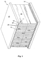
- the heatsink 10 comprises two opposing base plates 12, each base plate having an inward-facing surface 14. Landing areas 11 of base plate 12 are separated by channels 16 and comprise an elongate jaw pair 18, having jaws 20. Fins 22 have flared ends 24 that fit in between adjacent jaw pairs 18 of respective base plates 12. The channels 16 in the surface 14 between the jaw pairs 18 receive the flared ends 24 of the fins 22. As can be seen from the diagram, the fins 22 are held in place by jaws 20 which have been swaged towards the fins 22 to apply pressure to the flared ends 24 of the fins 22. The advantage of the flared ends 24 of the fins 22 is that when the jaws 20 have been swaged, a more uniform and secure fit is achieved for increased heat transfer.
- FIG. 2 there is shown a heatsink 10 being made according to the method of the present invention, wherein a fin 22 is being lowered into one of the channels 16 between landing areas 11 of a base plate 12. Once all of the fins 22 have been placed into corresponding channels 16 between said jaw pairs 18, the second base plate 12 is fit onto the flared ends 24 of the fins 22.
- FIG. 3 there is shown a front view of the heatsink 10 being made according to the principles of the present invention.
- the fins 22 have been placed into corresponding channels 16 between landing areas 11 of the base plates 12, and a swaging tool 40 (fully illustrated in Figure 7) has been placed through the fins 22 and into the space between jaws 20 in each jaw pair 18.
- This diagram shows clearly the flared ends 24 of the fins 22 in between jaw pairs 18.
- each jaw 20 is shown clearly.
- the jaws 20 progressively widen in cross section from the end distal to the surface 14 of the base plate 12 towards the surface 14, and then narrow again.
- the base plates are maintained at a constant relative distance, as discussed in greater detail below with reference to Figure 7.
- the widening of the jaws 20 cooperates with the wedge shape of the swaging tool 40 to progressively force the jaws 20 apart when the tines 42 of the swaging tool 40 are being passed between the respective jaws 20 in the jaw pairs 18.
- the narrowing ensures that swaging the jaws 20 causes minimal warping of the base plates 12 because of a lower bending moment.
- the tines 42 of the swaging tool 40 are caused to slide in a direction parallel to the surfaces 14 of base plates 12 and between the jaws 20. Because the tines 42 of the swaging tool 40, shown more clearly in Figures 5 - 7, are increased in height towards its second end, they push against the jaws 20 of the landing area 11 to swage them apart and against the flared ends 24 of the fins 22. Because the base plates 12 are being maintained at a constant relative distance, the jaws 20 are forced apart due to the increase in pressure from the tines 42 as the swaging tool 40 is pulled through the fins 22. The flared ends 24 of the fins 22 are pressed into channels 16 of each base plate 12 and, because the jaws 20 of base plates 12 have been deformed, are retained therein.
- Figures 5 and 6 show a side cutaway view of a single tine 42 of the swaging tool 40 being passed between the base plates 12. As can be seen, the widened second end of the tine 42 pushes against both jaw pairs 18 of the landing areas 11 on both base plates 12 to progressively force open the jaws 20 and push them against the flared ends 24 of the fin 22.
- FIG. 7 shows an exemplary view of the apparatus used to form the heatsink 10 according to the present invention.
- the uncoupled heatsink 10 is placed in a retaining structure having expansion-preventing walls 50 to maintain the base plates 12 at a constant relative distance.
- the swaging tool 40 is shown having multiple tines 42 that are each pulled past the fins 22 of the heatsink 10 to force open the jaws 20 in each jaw pair 18 of the landing area 11 so that the jaws 20 push against the flared ends 24 of the fins 22 to hold them in place in the channel 16 of the base plate 12.
- the tines 42 are pulled by a shaft 54 passing through a hole in each tine.
- the shaft is, in turn, pulled by a hydraulic motor or other motive apparatus.
- An alternate shaft attachment hole 56 is shown in each of the tines 42.
- slide-preventing walls 52 which act to prevent the fins 22 from sliding relative to the base plates 12 when the tines 42 of said swaging tool 40 are pulled from left to right.
- the slide-preventing walls avoid the requirement set forth in U.S. Patent No. 5,406,698 to, after coupling of the fins 22 to the base plates 12, remove the parts of the fins 22 that have slid relative to the base plates 12 during application of swaging pressure.
- a person understanding the present invention may conceive of alternatives and variations thereof.
- a pressure force can be applied to both base plates to increase the friction force between the fins and the base plates thereby reducing or prevent any relative movement.
- the flared fin ends of the preferred embodiment provide a more uniform fit for better heat transfer with the jaw pairs when swaged, uniform thickness fins can also be used.
- An alternative to the smooth-sided fin shape, whether flared or not, is to provide serrations on the end of the fin to improve bonding when the base plate material is deformed against the fin.
Landscapes
- Cooling Or The Like Of Semiconductors Or Solid State Devices (AREA)
- Pressure Welding/Diffusion-Bonding (AREA)
- Moulds For Moulding Plastics Or The Like (AREA)
- Physical Or Chemical Processes And Apparatus (AREA)
- Surface Heating Bodies (AREA)
Applications Claiming Priority (1)
| Application Number | Priority Date | Filing Date | Title |
|---|---|---|---|
| US11/106,440 US7497013B2 (en) | 2005-04-15 | 2005-04-15 | Method and apparatus for coupling fins in a high-fin density heatsink to dual heat-dissipating base plates |
Publications (3)
| Publication Number | Publication Date |
|---|---|
| EP1713120A2 true EP1713120A2 (de) | 2006-10-18 |
| EP1713120A3 EP1713120A3 (de) | 2008-01-23 |
| EP1713120B1 EP1713120B1 (de) | 2010-05-19 |
Family
ID=36601139
Family Applications (1)
| Application Number | Title | Priority Date | Filing Date |
|---|---|---|---|
| EP06007763A Expired - Lifetime EP1713120B1 (de) | 2005-04-15 | 2006-04-13 | Methode und Apparat zur Herstellung von Kühlkörpern hoher Lamellendichte |
Country Status (7)
| Country | Link |
|---|---|
| US (2) | US7497013B2 (de) |
| EP (1) | EP1713120B1 (de) |
| AT (1) | ATE468604T1 (de) |
| CA (2) | CA2651842C (de) |
| DE (1) | DE602006014320D1 (de) |
| DK (1) | DK1713120T3 (de) |
| ES (1) | ES2342186T3 (de) |
Cited By (3)
| Publication number | Priority date | Publication date | Assignee | Title |
|---|---|---|---|---|
| EP2204245A1 (de) * | 2008-12-31 | 2010-07-07 | Rich Sphere Precision Industry Co., Ltd. | Verfahren zur Kühlkörpermontage |
| US9398723B2 (en) | 2013-08-29 | 2016-07-19 | Eaton Corporation | Apparatus and methods using heat pipes for linking electronic assemblies that unequally produce heat |
| CN115776801A (zh) * | 2021-09-06 | 2023-03-10 | 可成科技股份有限公司 | 散热机构与其制造方法 |
Families Citing this family (24)
| Publication number | Priority date | Publication date | Assignee | Title |
|---|---|---|---|---|
| TWI262760B (en) * | 2005-05-20 | 2006-09-21 | Shr-Ming Chen | Riveting process of bottom plate of heat-dissipating device and fins |
| FR2898668B1 (fr) * | 2006-03-15 | 2008-06-27 | Ferraz Date Ind Soc Par Action | Echangeur de chaleur destine au refroidissement d'un composant electronique et son procede de fabrication |
| TW200934362A (en) * | 2008-01-16 | 2009-08-01 | Neng Tyi Prec Ind Co Ltd | Method of manufacturing heat dissipaters having heat sinks and structure thereof |
| US8225512B2 (en) | 2008-03-05 | 2012-07-24 | Surgical Site Solutions, Inc. | Vacuum device for hair clippings |
| CN101534626B (zh) * | 2008-03-14 | 2011-06-08 | 富准精密工业(深圳)有限公司 | 散热模组组合及其散热器组合 |
| US20100326644A1 (en) * | 2009-06-30 | 2010-12-30 | Shui-Hsu Hung | Plane-type heat-dissipating structure with high heat-dissipating effect and method for manufacturing the same |
| USD634278S1 (en) * | 2009-10-15 | 2011-03-15 | Sapa Ab | Heat sink |
| CN102166714B (zh) * | 2010-02-26 | 2013-04-24 | 苏州春兴精工股份有限公司 | 一种散热片装配器具 |
| CN102401358B (zh) * | 2010-09-10 | 2016-08-03 | 欧司朗股份有限公司 | 冷却体的制造方法、冷却体以及具有该冷却体的照明装置 |
| US20130014917A1 (en) * | 2011-07-14 | 2013-01-17 | Tsung-Hsien Huang | Heat pipe-attached heat sink with bottom radiation fins |
| US20130153189A1 (en) * | 2011-12-18 | 2013-06-20 | Chia-Yu Lin | Heat dissipating fin, heat dissipating device and method of manufacturing the same |
| US12120994B2 (en) * | 2016-09-25 | 2024-10-22 | Scynce Led Llc | Method and apparatus for an horticultural light fixture |
| JP6462737B2 (ja) * | 2017-01-24 | 2019-01-30 | 三菱電機株式会社 | ヒートシンク |
| WO2018161498A1 (zh) * | 2017-03-07 | 2018-09-13 | 上海嘉熙科技有限公司 | 热超导翅片式散热器及电器设备机箱 |
| CN107640597A (zh) * | 2017-10-11 | 2018-01-30 | 苏州新元电器有限公司 | 一种翅片换热器的翅片码放装置 |
| JP6555374B1 (ja) * | 2018-03-13 | 2019-08-07 | 日本電気株式会社 | 冷却構造、実装構造 |
| CN209879238U (zh) * | 2019-04-29 | 2019-12-31 | 中强光电股份有限公司 | 散热装置及投影机 |
| CN110479852A (zh) * | 2019-09-12 | 2019-11-22 | 苏州翰裴精密机械有限公司 | 一种用于散热器翅片加工的铲齿模具 |
| US11786959B2 (en) * | 2019-10-21 | 2023-10-17 | Huizhou Hanxu Hardware & Plastic Technology Co., Ltd. | Double-sided expanded plate riveting structure and method |
| CN113385915B (zh) * | 2021-07-05 | 2022-04-08 | 全椒赛德利机械有限公司 | 基于管片式散热器加工用散热片叠合排列装置 |
| CN116810337B (zh) * | 2022-12-20 | 2026-05-05 | 上海裕纪金属制品有限公司 | 双头铆接散热器及双头铆接散热器加工装置及加工方法 |
| CN116372550B (zh) * | 2023-04-24 | 2025-06-20 | Ihi寿力压缩技术(苏州)有限公司 | 一种免焊接的水分离器翅片安装方法 |
| CN118288000B (zh) * | 2024-04-22 | 2024-08-20 | 东莞市仁信精工实业有限公司 | 一种插片散热器加工快速成型设备 |
| CN118162879B (zh) * | 2024-05-16 | 2024-07-23 | 博特换热系统(江苏)有限公司 | 一种散热片的组装装置及其使用方法 |
Family Cites Families (23)
| Publication number | Priority date | Publication date | Assignee | Title |
|---|---|---|---|---|
| DE3814145C2 (de) * | 1988-04-27 | 1998-07-23 | Hess Joachim | Vorrichtung zum Zuführen oder Abführen von Wärme |
| US5542176A (en) * | 1992-09-21 | 1996-08-06 | Hideaki Serizawa | Radiation plate and method of producing the same |
| CA2107869C (en) * | 1993-10-06 | 1998-05-05 | Joseph Lipinski | Method and apparatus for fabricating high fin density heatsinks |
| CA2216999A1 (en) * | 1995-04-11 | 1996-10-17 | Fmc Corporation | Termite bait station |
| US5564826A (en) * | 1995-09-27 | 1996-10-15 | Robbins Scientific Corporation | Reciprocating bath shaker |
| US5771966A (en) * | 1995-12-15 | 1998-06-30 | Jacoby; John | Folded conducting member heatsinks and method of making same |
| EP0789396B1 (de) * | 1996-01-31 | 2006-06-14 | Alcan Technology & Management AG | Kühlkörper für Halbleiterbauelemente od. dgl. |
| DE29601776U1 (de) | 1996-02-02 | 1996-06-13 | Alusuisse-Lonza Services AG, Neuhausen am Rheinfall | Kühlkörper für Halbleiterbauelemente o.dgl. |
| US5937517A (en) * | 1997-11-12 | 1999-08-17 | Eastman Kodak Company | Method of manufacturing bonded dual extruded, high fin density heat sinks |
| DE19900970A1 (de) | 1999-01-13 | 2000-07-20 | Joachim Glueck | Kühlkörper mit Rippenabstandsprofil |
| US6538991B1 (en) * | 1999-08-03 | 2003-03-25 | Lucent Technologies Inc. | Constraint-based routing between ingress-egress points in a packet network |
| DE20006937U1 (de) * | 2000-04-14 | 2000-08-17 | Hsieh, Hsin-Mao, Kaohsiung | Anordnung zum Ableiten von Wärme |
| US6520248B2 (en) * | 2000-05-18 | 2003-02-18 | Aavid Thermalloy Llc | Heat sink having bonded cooling fins |
| CA2353338A1 (en) * | 2000-07-21 | 2002-01-21 | Ats Automation Tooling Systems Inc. | Folded-fin heat sink manufacturing method and apparatus |
| JP2002118211A (ja) * | 2000-10-12 | 2002-04-19 | Mizutani Denki Kogyo Kk | 電子部品の放熱器およびその製造方法 |
| JP3552047B2 (ja) * | 2000-10-25 | 2004-08-11 | 古河電気工業株式会社 | ヒートシンク、その製造方法、および、押圧治具 |
| DE10056387B4 (de) | 2000-11-14 | 2008-11-13 | Corus Aluminium Profiltechnik Gmbh | Kühlvorrichtung und Verfahren zu deren Herstellung sowie Vorrichtung zur Durchführung des Verfahrens |
| JP4457487B2 (ja) | 2000-11-15 | 2010-04-28 | パナソニック株式会社 | スピーカの製造方法 |
| WO2002093997A1 (en) * | 2001-05-11 | 2002-11-21 | Parker Hannifin Corporation | Notched gasket for low closure force emi shielding applications |
| KR100411251B1 (ko) * | 2001-11-28 | 2003-12-18 | 한국전자통신연구원 | 제한조건을 만족하는 다중 경로 배정방법 |
| KR100450407B1 (ko) * | 2002-08-28 | 2004-09-30 | 한국전자통신연구원 | 서비스 품질(QoS)보장 다중경로 계산방법 |
| DE202004009712U1 (de) | 2004-06-21 | 2004-11-18 | Chen, Shyh-Ming, Shulin | Vorrichtung zur Herstellung von Wärmeableitvorrichtungen durch Rammen sowie auf diese Weise hergestellte Wärmeableitvorrichtung |
| US7466520B2 (en) * | 2004-10-07 | 2008-12-16 | Seagate Technology Llc | Co-located microactuator lever assembly |
-
2005
- 2005-04-15 US US11/106,440 patent/US7497013B2/en active Active
-
2006
- 2006-04-06 CA CA2651842A patent/CA2651842C/en not_active Expired - Fee Related
- 2006-04-06 CA CA002542169A patent/CA2542169C/en not_active Expired - Fee Related
- 2006-04-13 DE DE602006014320T patent/DE602006014320D1/de not_active Expired - Lifetime
- 2006-04-13 ES ES06007763T patent/ES2342186T3/es not_active Expired - Lifetime
- 2006-04-13 AT AT06007763T patent/ATE468604T1/de active
- 2006-04-13 EP EP06007763A patent/EP1713120B1/de not_active Expired - Lifetime
- 2006-04-13 DK DK06007763.3T patent/DK1713120T3/da active
-
2009
- 2009-01-21 US US12/356,654 patent/US7819173B2/en not_active Expired - Fee Related
Cited By (3)
| Publication number | Priority date | Publication date | Assignee | Title |
|---|---|---|---|---|
| EP2204245A1 (de) * | 2008-12-31 | 2010-07-07 | Rich Sphere Precision Industry Co., Ltd. | Verfahren zur Kühlkörpermontage |
| US9398723B2 (en) | 2013-08-29 | 2016-07-19 | Eaton Corporation | Apparatus and methods using heat pipes for linking electronic assemblies that unequally produce heat |
| CN115776801A (zh) * | 2021-09-06 | 2023-03-10 | 可成科技股份有限公司 | 散热机构与其制造方法 |
Also Published As
| Publication number | Publication date |
|---|---|
| DE602006014320D1 (de) | 2010-07-01 |
| ES2342186T3 (es) | 2010-07-02 |
| US7497013B2 (en) | 2009-03-03 |
| US7819173B2 (en) | 2010-10-26 |
| US20060230616A1 (en) | 2006-10-19 |
| CA2651842A1 (en) | 2006-10-15 |
| CA2542169A1 (en) | 2006-10-15 |
| CA2651842C (en) | 2013-02-05 |
| ATE468604T1 (de) | 2010-06-15 |
| CA2542169C (en) | 2009-05-26 |
| US20090178796A1 (en) | 2009-07-16 |
| EP1713120B1 (de) | 2010-05-19 |
| EP1713120A3 (de) | 2008-01-23 |
| DK1713120T3 (da) | 2010-08-30 |
Similar Documents
| Publication | Publication Date | Title |
|---|---|---|
| US7819173B2 (en) | Base plate for a dual base plate heatsink | |
| JP3552047B2 (ja) | ヒートシンク、その製造方法、および、押圧治具 | |
| EP1172852B1 (de) | Gewölbter Matrixkühlkörper zum Kühlen von elektronischen Bauteilen | |
| US20030056368A1 (en) | Method for manufacturing a heat sink | |
| RU2217886C2 (ru) | Радиатор для электронного компонента, устройство и способ для его изготовления | |
| US6644386B1 (en) | Engaging mechanism for heat-dissipating member | |
| WO2009093618A1 (ja) | コルゲートフィン型放熱器 | |
| JP2010129774A (ja) | 一体型ピンフィンヒートシンクの製造方法 | |
| US7322102B2 (en) | Isothermal plate assembly with predetermined shape and method for manufacturing the same | |
| JP2002043477A (ja) | ヒートシンク及びその製造方法 | |
| JPH07193383A (ja) | ヒートシンク及びその製造方法並びにその加工用治具 | |
| US7237338B2 (en) | Method for manufacturing heat-dissipating device with isothermal plate assembly of predetermined shape | |
| CN111132530A (zh) | 一种电器快装散热装置和制造方法 | |
| JP6775772B1 (ja) | ヒートシンク製造方法とヒートシンク | |
| CN103369918A (zh) | 散热装置及其组装方法 | |
| JP2001308231A (ja) | 電子部品の放熱器およびその製造方法 | |
| JP2002026200A (ja) | 電子部品の放熱器 | |
| JP2916129B1 (ja) | 溝付き板状部材の製造方法 | |
| JP2002299864A (ja) | コルゲートフィン型ヒートシンク | |
| JP2004022830A (ja) | ヒートシンク | |
| JP4762414B2 (ja) | 一体の放熱基板に接合された複数のヒートパイプに放熱フィンを圧入して挿通するヒートシンクの製造方法 | |
| KR100829044B1 (ko) | 히트싱크 및 그 제조방법 | |
| CN210091082U (zh) | 一种散热片与导热体无焊紧配结构 | |
| CN114302621A (zh) | 一种散热片、散热结构及加工方法 | |
| JPH11179465A (ja) | 熱交換器の製造装置および製造方法 |
Legal Events
| Date | Code | Title | Description |
|---|---|---|---|
| PUAI | Public reference made under article 153(3) epc to a published international application that has entered the european phase |
Free format text: ORIGINAL CODE: 0009012 |
|
| AK | Designated contracting states |
Kind code of ref document: A2 Designated state(s): AT BE BG CH CY CZ DE DK EE ES FI FR GB GR HU IE IS IT LI LT LU LV MC NL PL PT RO SE SI SK TR |
|
| AX | Request for extension of the european patent |
Extension state: AL BA HR MK YU |
|
| PUAL | Search report despatched |
Free format text: ORIGINAL CODE: 0009013 |
|
| AK | Designated contracting states |
Kind code of ref document: A3 Designated state(s): AT BE BG CH CY CZ DE DK EE ES FI FR GB GR HU IE IS IT LI LT LU LV MC NL PL PT RO SE SI SK TR |
|
| AX | Request for extension of the european patent |
Extension state: AL BA HR MK YU |
|
| 17P | Request for examination filed |
Effective date: 20080529 |
|
| AKX | Designation fees paid |
Designated state(s): AT BE BG CH CY CZ DE DK EE ES FI FR GB GR HU IE IS IT LI LT LU LV MC NL PL PT RO SE SI SK TR |
|
| GRAP | Despatch of communication of intention to grant a patent |
Free format text: ORIGINAL CODE: EPIDOSNIGR1 |
|
| GRAS | Grant fee paid |
Free format text: ORIGINAL CODE: EPIDOSNIGR3 |
|
| GRAA | (expected) grant |
Free format text: ORIGINAL CODE: 0009210 |
|
| AK | Designated contracting states |
Kind code of ref document: B1 Designated state(s): AT BE BG CH CY CZ DE DK EE ES FI FR GB GR HU IE IS IT LI LT LU LV MC NL PL PT RO SE SI SK TR |
|
| REG | Reference to a national code |
Ref country code: GB Ref legal event code: FG4D |
|
| REG | Reference to a national code |
Ref country code: CH Ref legal event code: EP |
|
| REG | Reference to a national code |
Ref country code: IE Ref legal event code: FG4D |
|
| REF | Corresponds to: |
Ref document number: 602006014320 Country of ref document: DE Date of ref document: 20100701 Kind code of ref document: P |
|
| REG | Reference to a national code |
Ref country code: ES Ref legal event code: FG2A Ref document number: 2342186 Country of ref document: ES Kind code of ref document: T3 |
|
| REG | Reference to a national code |
Ref country code: CH Ref legal event code: NV Representative=s name: TROESCH SCHEIDEGGER WERNER AG |
|
| REG | Reference to a national code |
Ref country code: NL Ref legal event code: T3 |
|
| REG | Reference to a national code |
Ref country code: SE Ref legal event code: TRGR |
|
| REG | Reference to a national code |
Ref country code: DK Ref legal event code: T3 |
|
| LTIE | Lt: invalidation of european patent or patent extension |
Effective date: 20100519 |
|
| PG25 | Lapsed in a contracting state [announced via postgrant information from national office to epo] |
Ref country code: LT Free format text: LAPSE BECAUSE OF FAILURE TO SUBMIT A TRANSLATION OF THE DESCRIPTION OR TO PAY THE FEE WITHIN THE PRESCRIBED TIME-LIMIT Effective date: 20100519 |
|
| PG25 | Lapsed in a contracting state [announced via postgrant information from national office to epo] |
Ref country code: FI Free format text: LAPSE BECAUSE OF FAILURE TO SUBMIT A TRANSLATION OF THE DESCRIPTION OR TO PAY THE FEE WITHIN THE PRESCRIBED TIME-LIMIT Effective date: 20100519 Ref country code: SI Free format text: LAPSE BECAUSE OF FAILURE TO SUBMIT A TRANSLATION OF THE DESCRIPTION OR TO PAY THE FEE WITHIN THE PRESCRIBED TIME-LIMIT Effective date: 20100519 Ref country code: IS Free format text: LAPSE BECAUSE OF FAILURE TO SUBMIT A TRANSLATION OF THE DESCRIPTION OR TO PAY THE FEE WITHIN THE PRESCRIBED TIME-LIMIT Effective date: 20100919 Ref country code: LV Free format text: LAPSE BECAUSE OF FAILURE TO SUBMIT A TRANSLATION OF THE DESCRIPTION OR TO PAY THE FEE WITHIN THE PRESCRIBED TIME-LIMIT Effective date: 20100519 |
|
| PG25 | Lapsed in a contracting state [announced via postgrant information from national office to epo] |
Ref country code: PL Free format text: LAPSE BECAUSE OF FAILURE TO SUBMIT A TRANSLATION OF THE DESCRIPTION OR TO PAY THE FEE WITHIN THE PRESCRIBED TIME-LIMIT Effective date: 20100519 Ref country code: CY Free format text: LAPSE BECAUSE OF FAILURE TO SUBMIT A TRANSLATION OF THE DESCRIPTION OR TO PAY THE FEE WITHIN THE PRESCRIBED TIME-LIMIT Effective date: 20100519 Ref country code: GR Free format text: LAPSE BECAUSE OF FAILURE TO SUBMIT A TRANSLATION OF THE DESCRIPTION OR TO PAY THE FEE WITHIN THE PRESCRIBED TIME-LIMIT Effective date: 20100820 |
|
| PG25 | Lapsed in a contracting state [announced via postgrant information from national office to epo] |
Ref country code: EE Free format text: LAPSE BECAUSE OF FAILURE TO SUBMIT A TRANSLATION OF THE DESCRIPTION OR TO PAY THE FEE WITHIN THE PRESCRIBED TIME-LIMIT Effective date: 20100519 Ref country code: PT Free format text: LAPSE BECAUSE OF FAILURE TO SUBMIT A TRANSLATION OF THE DESCRIPTION OR TO PAY THE FEE WITHIN THE PRESCRIBED TIME-LIMIT Effective date: 20100920 |
|
| PG25 | Lapsed in a contracting state [announced via postgrant information from national office to epo] |
Ref country code: RO Free format text: LAPSE BECAUSE OF FAILURE TO SUBMIT A TRANSLATION OF THE DESCRIPTION OR TO PAY THE FEE WITHIN THE PRESCRIBED TIME-LIMIT Effective date: 20100519 Ref country code: SK Free format text: LAPSE BECAUSE OF FAILURE TO SUBMIT A TRANSLATION OF THE DESCRIPTION OR TO PAY THE FEE WITHIN THE PRESCRIBED TIME-LIMIT Effective date: 20100519 Ref country code: CZ Free format text: LAPSE BECAUSE OF FAILURE TO SUBMIT A TRANSLATION OF THE DESCRIPTION OR TO PAY THE FEE WITHIN THE PRESCRIBED TIME-LIMIT Effective date: 20100519 |
|
| PLBE | No opposition filed within time limit |
Free format text: ORIGINAL CODE: 0009261 |
|
| STAA | Information on the status of an ep patent application or granted ep patent |
Free format text: STATUS: NO OPPOSITION FILED WITHIN TIME LIMIT |
|
| 26N | No opposition filed |
Effective date: 20110222 |
|
| REG | Reference to a national code |
Ref country code: DE Ref legal event code: R097 Ref document number: 602006014320 Country of ref document: DE Effective date: 20110221 |
|
| PG25 | Lapsed in a contracting state [announced via postgrant information from national office to epo] |
Ref country code: MC Free format text: LAPSE BECAUSE OF NON-PAYMENT OF DUE FEES Effective date: 20110430 |
|
| REG | Reference to a national code |
Ref country code: IE Ref legal event code: MM4A |
|
| PG25 | Lapsed in a contracting state [announced via postgrant information from national office to epo] |
Ref country code: IE Free format text: LAPSE BECAUSE OF NON-PAYMENT OF DUE FEES Effective date: 20120413 |
|
| PG25 | Lapsed in a contracting state [announced via postgrant information from national office to epo] |
Ref country code: LU Free format text: LAPSE BECAUSE OF NON-PAYMENT OF DUE FEES Effective date: 20110413 |
|
| REG | Reference to a national code |
Ref country code: IE Ref legal event code: NE4A |
|
| PG25 | Lapsed in a contracting state [announced via postgrant information from national office to epo] |
Ref country code: TR Free format text: LAPSE BECAUSE OF FAILURE TO SUBMIT A TRANSLATION OF THE DESCRIPTION OR TO PAY THE FEE WITHIN THE PRESCRIBED TIME-LIMIT Effective date: 20100519 Ref country code: BG Free format text: LAPSE BECAUSE OF FAILURE TO SUBMIT A TRANSLATION OF THE DESCRIPTION OR TO PAY THE FEE WITHIN THE PRESCRIBED TIME-LIMIT Effective date: 20100819 |
|
| PG25 | Lapsed in a contracting state [announced via postgrant information from national office to epo] |
Ref country code: HU Free format text: LAPSE BECAUSE OF FAILURE TO SUBMIT A TRANSLATION OF THE DESCRIPTION OR TO PAY THE FEE WITHIN THE PRESCRIBED TIME-LIMIT Effective date: 20100519 |
|
| PGRI | Patent reinstated in contracting state [announced from national office to epo] |
Ref country code: IE Effective date: 20131111 |
|
| REG | Reference to a national code |
Ref country code: FR Ref legal event code: PLFP Year of fee payment: 11 |
|
| PGFP | Annual fee paid to national office [announced via postgrant information from national office to epo] |
Ref country code: NL Payment date: 20160426 Year of fee payment: 11 |
|
| PGFP | Annual fee paid to national office [announced via postgrant information from national office to epo] |
Ref country code: CH Payment date: 20160427 Year of fee payment: 11 Ref country code: IE Payment date: 20160428 Year of fee payment: 11 Ref country code: DE Payment date: 20160427 Year of fee payment: 11 Ref country code: ES Payment date: 20160426 Year of fee payment: 11 Ref country code: GB Payment date: 20160427 Year of fee payment: 11 |
|
| PGFP | Annual fee paid to national office [announced via postgrant information from national office to epo] |
Ref country code: BE Payment date: 20160427 Year of fee payment: 11 Ref country code: FR Payment date: 20160425 Year of fee payment: 11 Ref country code: SE Payment date: 20160427 Year of fee payment: 11 Ref country code: DK Payment date: 20160425 Year of fee payment: 11 Ref country code: IT Payment date: 20160421 Year of fee payment: 11 Ref country code: AT Payment date: 20160321 Year of fee payment: 11 |
|
| REG | Reference to a national code |
Ref country code: DE Ref legal event code: R119 Ref document number: 602006014320 Country of ref document: DE |
|
| REG | Reference to a national code |
Ref country code: DK Ref legal event code: EBP Effective date: 20170430 |
|
| REG | Reference to a national code |
Ref country code: CH Ref legal event code: PL |
|
| REG | Reference to a national code |
Ref country code: NL Ref legal event code: MM Effective date: 20170501 |
|
| REG | Reference to a national code |
Ref country code: AT Ref legal event code: MM01 Ref document number: 468604 Country of ref document: AT Kind code of ref document: T Effective date: 20170413 |
|
| GBPC | Gb: european patent ceased through non-payment of renewal fee |
Effective date: 20170413 |
|
| REG | Reference to a national code |
Ref country code: IE Ref legal event code: MM4A |
|
| REG | Reference to a national code |
Ref country code: FR Ref legal event code: ST Effective date: 20171229 |
|
| PG25 | Lapsed in a contracting state [announced via postgrant information from national office to epo] |
Ref country code: NL Free format text: LAPSE BECAUSE OF NON-PAYMENT OF DUE FEES Effective date: 20170501 Ref country code: DE Free format text: LAPSE BECAUSE OF NON-PAYMENT OF DUE FEES Effective date: 20171103 Ref country code: AT Free format text: LAPSE BECAUSE OF NON-PAYMENT OF DUE FEES Effective date: 20170413 Ref country code: FR Free format text: LAPSE BECAUSE OF NON-PAYMENT OF DUE FEES Effective date: 20170502 |
|
| PG25 | Lapsed in a contracting state [announced via postgrant information from national office to epo] |
Ref country code: SE Free format text: LAPSE BECAUSE OF NON-PAYMENT OF DUE FEES Effective date: 20170414 Ref country code: GB Free format text: LAPSE BECAUSE OF NON-PAYMENT OF DUE FEES Effective date: 20170413 Ref country code: CH Free format text: LAPSE BECAUSE OF NON-PAYMENT OF DUE FEES Effective date: 20170430 Ref country code: LI Free format text: LAPSE BECAUSE OF NON-PAYMENT OF DUE FEES Effective date: 20170430 |
|
| REG | Reference to a national code |
Ref country code: BE Ref legal event code: MM Effective date: 20170430 |
|
| PG25 | Lapsed in a contracting state [announced via postgrant information from national office to epo] |
Ref country code: DK Free format text: LAPSE BECAUSE OF NON-PAYMENT OF DUE FEES Effective date: 20170430 Ref country code: IE Free format text: LAPSE BECAUSE OF NON-PAYMENT OF DUE FEES Effective date: 20170413 |
|
| PG25 | Lapsed in a contracting state [announced via postgrant information from national office to epo] |
Ref country code: IT Free format text: LAPSE BECAUSE OF NON-PAYMENT OF DUE FEES Effective date: 20170413 Ref country code: BE Free format text: LAPSE BECAUSE OF NON-PAYMENT OF DUE FEES Effective date: 20170430 |
|
| REG | Reference to a national code |
Ref country code: ES Ref legal event code: FD2A Effective date: 20180629 |
|
| PG25 | Lapsed in a contracting state [announced via postgrant information from national office to epo] |
Ref country code: ES Free format text: LAPSE BECAUSE OF NON-PAYMENT OF DUE FEES Effective date: 20170414 |