EP1714568A1 - Casque avec déflecteur de vent - Google Patents
Casque avec déflecteur de vent Download PDFInfo
- Publication number
- EP1714568A1 EP1714568A1 EP06250332A EP06250332A EP1714568A1 EP 1714568 A1 EP1714568 A1 EP 1714568A1 EP 06250332 A EP06250332 A EP 06250332A EP 06250332 A EP06250332 A EP 06250332A EP 1714568 A1 EP1714568 A1 EP 1714568A1
- Authority
- EP
- European Patent Office
- Prior art keywords
- helmet
- straightening member
- straightening
- mentioned
- angle
- Prior art date
- Legal status (The legal status is an assumption and is not a legal conclusion. Google has not performed a legal analysis and makes no representation as to the accuracy of the status listed.)
- Granted
Links
- 230000036544 posture Effects 0.000 claims abstract description 13
- 238000009423 ventilation Methods 0.000 claims description 51
- 238000007373 indentation Methods 0.000 description 12
- PPBRXRYQALVLMV-UHFFFAOYSA-N Styrene Chemical compound C=CC1=CC=CC=C1 PPBRXRYQALVLMV-UHFFFAOYSA-N 0.000 description 4
- 230000000694 effects Effects 0.000 description 3
- 239000000463 material Substances 0.000 description 3
- 230000005465 channeling Effects 0.000 description 2
- 230000002708 enhancing effect Effects 0.000 description 2
- 230000002349 favourable effect Effects 0.000 description 2
- NJPPVKZQTLUDBO-UHFFFAOYSA-N novaluron Chemical compound C1=C(Cl)C(OC(F)(F)C(OC(F)(F)F)F)=CC=C1NC(=O)NC(=O)C1=C(F)C=CC=C1F NJPPVKZQTLUDBO-UHFFFAOYSA-N 0.000 description 2
- JOYRKODLDBILNP-UHFFFAOYSA-N Ethyl urethane Chemical compound CCOC(N)=O JOYRKODLDBILNP-UHFFFAOYSA-N 0.000 description 1
- 230000003247 decreasing effect Effects 0.000 description 1
- 238000006073 displacement reaction Methods 0.000 description 1
- 239000000835 fiber Substances 0.000 description 1
- 238000012986 modification Methods 0.000 description 1
- 230000004048 modification Effects 0.000 description 1
- 239000011347 resin Substances 0.000 description 1
- 229920005989 resin Polymers 0.000 description 1
- 238000004904 shortening Methods 0.000 description 1
Images




Classifications
-
- A—HUMAN NECESSITIES
- A42—HEADWEAR
- A42B—HATS; HEAD COVERINGS
- A42B3/00—Helmets; Helmet covers ; Other protective head coverings
- A42B3/04—Parts, details or accessories of helmets
- A42B3/28—Ventilating arrangements
-
- A—HUMAN NECESSITIES
- A42—HEADWEAR
- A42B—HATS; HEAD COVERINGS
- A42B3/00—Helmets; Helmet covers ; Other protective head coverings
- A42B3/04—Parts, details or accessories of helmets
- A42B3/0493—Aerodynamic helmets; Air guiding means therefor
-
- A—HUMAN NECESSITIES
- A42—HEADWEAR
- A42B—HATS; HEAD COVERINGS
- A42B3/00—Helmets; Helmet covers ; Other protective head coverings
- A42B3/04—Parts, details or accessories of helmets
Definitions
- the present invention relates to a helmet which a driver wears when he rides on various kinds of vessels and vehicles such as a motorcycle, and a automobile, a motorboat or a bicycle, and more particularly to a helmet which has a ventilation structure in the helmet and a straightening structure for channeling off a traveling wind from a surface of the helmet.
- Patent Document 1 Japanese Patent Laid-Open No. 2000-328343
- Patent Document 2 Japanese Patent Laid-Open No. 2000-328343
- Patent Document 1 The constitution described in the above-mentioned Patent Document 1 is characterized in that a portion which performs the channeling-off of a traveling wind (a rear straightening member) and a portion which performs the ventilation (a passage forming member) are mounted on a surface of a helmet body as an integral structure.
- Patent Document 2 the constitution described in the above-mentioned Patent Document 2 is also characterized in that a portion which performs the channeling-off of a traveling wind (an air flow deflection surface) and a portion which performs the ventilation (a ventilation port) are mounted on a surface of a helmet body as an integral structure.
- Patent Document 1 and Patent Document 2 are useful from a viewpoint of enhancing a ventilation action and a straightening action by channeling-off the above-mentioned traveling wind.
- the portion which performs the channeling-off of the traveling wind and the portion which performs the ventilation are integrally formed and, at the same time, these portions are mounted on fixed positions on the surface of the helmet body in an immobile state. Accordingly, there may be a case that a targeted channeling function cannot be sufficiently obtained depending on the difference in intrinsic driving postures of helmet wearers, speeds of vehicles and the like.
- the present invention adopts following technical means.
- the technical means is directed to a helmet which mounts a straightening member relating to holding of stability of the helmet against flow of air during traveling on a surface of a helmet body, wherein the straightening member is formed so as to allow a helmet wearer to adjust a position of the straighteningmember in a fore-and-aft direction corresponding to various intrinsic driving postures of the helmet wearer and a speed of vehicles.
- another technical means is directed to a helmet which mounts a straightening member relating to holding of stability of the helmet against flow of air during traveling on a surface of a helmet body, wherein the straightening member is formed so as to allow a helmet wearer to adjust an angle of a straightening surface which faces a traveling wind corresponding to various intrinsic driving postures of the helmet wearer and a speed of vehicles.
- Still another technical means is directed to a helmet which mounts a straightening member relating to holding of stability of the helmet against flow of air during traveling on a surface of a helmet body, wherein the straightening member is formed so as to allow a helmet wearer to adjust a position of the straightening member in a fore-and-aft direction and, at the same time, to adjust an angle of a straightening surface which faces a traveling wind corresponding to various intrinsic driving postures of the helmet wearer and a speed of vehicles.
- the straightening body is capable of adjusting a relative position thereof within a range that the straightening member is capable of straightening the flow of air in the vicinity of the ventilation port.
- the straightening member forms an integral structure with the ventilation cover.
- the structure which changes the position of the straightening member it is possible, for example, the structure which is a combination of an elongated hole which is formed along the fore-and-aft direction in one side of the straightening member or a support portion which supports the straightening member and a fitting member which is formed on another side and is fitted in the elongated hole and in which the fitting member holds the position of the straightening member and releases such holding, and the structure which forms ratchets on the straightening member and a support surface which supports the straightening member and in which the position of the straightening member is changed by moving the straightening member in the fore-and-aft direction against the fitting resistance of the ratchet.
- the structure which changes the angle of the straightening member it is possible, for example, the structure which includes an adjustment means which rotatably supports the front side of the straightening member so as to move the rear end of the straightening member vertically and holds the straightening member at predetermined position, and the structure which pivotally supports the front side of the straightening member and forms ratchets over the straightening member and a support surface which support the straightening member behind the pivotally supporting portion and moves the straightening member vertically against the fitting resistance of the ratchets so as to change the position of the straightening member.
- the present invention can expect following excellent effects due to the above-mentioned constitutions.
- the helmet wearer By allowing the helmet wearer to change the position of the straightening member to a position which corresponds to the various intrinsic driving postures of the helmet wearer and the speed of vehicles, it is helps to obtain the targeted traveling-wind channel-of function.
- the helmet wearer by allowing the helmet wearer to change the angle of the straightening member to an angle which corresponds to the various intrinsic driving postures of the helmet wearer and the speed of vehicles, it is possible to obtain the targeted traveling-wind channel-off function.
- the adjustment corresponding to the various intrinsic driving postures of the helmet wearer and the speed of a vehicles is enabled and hence, it helps to enhance the targeted traveling-wind channel-off function.
- the straightening is conducted in the vicinity of the ventilation port for ventilation and hence, it helps to efficiently perform the discharge from the discharge port. Due to this efficient discharge, it helps to allow the traveling wind to efficiently enter the inside of the helmet through an intake port and hence, it helps to expect the efficient ventilation in the helmet.
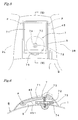
- Fig. 1 to Fig. 4 show the first embodiment (helmet A) of the present invention
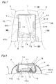
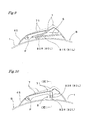
- Fig. 5 to Fig. 11 show the second embodiment (helmet B) of the present invention
- Fig. 12 and Fig. 13 show the third embodiment (helmet C) of the present invention.
- the basic constitution of the helmets A to C illustrated in the respective modes is configured as follows. That is, in the inside of a helmet body 1 which is formed in a given shape using a fiber reinforced resin material, an impact absorbing liner which is formed of foamed styrene or a material having an impact absorbing function equivalent to an impact absorbing function of the foamed styrene, a head interior member which is arranged inside the impact absorbing liner and is made of a urethane material or the like, and cheek pads are interiorly formed.
- a shield 2 is mounted on a front opening portion of the helmet body 1 in a state that the shield 2 can be opened and closed, wherein the shield 2 is provided with two ventilation ports, that is, left and right ventilation ports 2L, 2Rwhich discharge hot air inside the helmets A to C.
- the helmet illustrated in this mode for carrying out the invention is a full-face type helmet
- the present invention is not limited to the full-face type helmet and is also applicable to a jet type helmet and a half type helmet.
- the helmet A of this mode is characterized in that ventilation covers 3L, 3R which cover and conceal the above-mentioned ventilation ports 2L, 2R are mounted on a surface of the helmet body 1, and a position of a straightening member 4 can be changed due to the slide structure which allows the straightening member 4 to slide in the fore-and-aft direction along the ventilation covers 3L, 3R.
- the ventilation covers 3L, 3R of this mode are approximately tunnel-like covers which are formed to guide a traveling wind from a front side to a rear side of the helmet body 1.
- Each of the respective ventilation covers 3L, 3R forms an intake port 31 in a front end thereof and an discharge port 32 in a rear end thereof.
- the above-mentioned straightening member 4 is configured such that the straightening member 4 includes an elongated hole 42 for slide guiding on a front side and a straightening surface 41 on a rear side and, further, includes slide surfaces 43L, 43R which slide while being guided by the ventilation covers 3L, 3R.
- the straightening member 4 is mounted on the helmet body 1 by allowing a small screw 12 which fixes the position of the straightening member 4 or releases such fixing to be threadedly engaged with a screw hole 11 formed in the surface of the helmet body 1 between the above-mentioned ventilation covers 3L, 3R through the elongated hole 42.
- the straightening member 4 is allowed to be slidable in the fore-and-aft direction along the ventilation covers 3L, 3R by loosening or slackening the above-mentioned small bolt 12 and is held at the position by fastening the small bolt 12.
- the slide distance of the above-mentioned straightening member is ensured by an amount corresponding to a length of the elongated hole.
- the change of the slide distance can be realized by preparing the straightening members having elongated holes of different lengths and by exchanging one straightening member with another straightening member which has the targeted elongated hole (not shown in the drawing) .
- the slide structure of this mode is characterized in that the sliding and the fixing of the straightening member 4 are controlled by ratchets.
- the explanation of parts which overlap the above-mentioned parts is omitted by giving the same symbols to the parts.
- the straightening member 4 is mounted on the helmet body 1 in a state that the straightening member 4 is mounted on a fixed plate 44 which is fixedly secured to the surface of the helmet body 1 between the above-mentioned ventilation covers 3L, 3R by way of a ratchet 5 and a slide guide portion 6 which are formed over the fixed plate 44 and the straightening member 4.
- the ratchet 5 is configured such that fitting recessed portions 51L, 51R in two rows which form a large number of indentations 51 therein in the fore and aft direction of the above mentioned ventilation covers 3L, 3R are mounted on the fixed plate 44 and, at the same time, resilient fitting members 52L, 52R which are engaged with or disengaged from the indentations 51 formed in either one of the above-mentioned fitting recessed portions 51L, 51R are mounted on the above-mentioned straightening member 4.
- the slide guide portion 6 is configured such that latch projections 53L, 53R are mounted on the above-mentioned fixed plate 44 along the fitting recessed portions 51L, 51R in a state that the latch projections 53L, 53R are arranged outside the above-mentioned fitting recessed portions 51L, 51R, while slide projections 54L, 54R which are slidably engaged with the above-mentioned latch projections 53L, 53R are mounted on the straightening member 4.
- the position of the straightening member 4 is held by the engagement of the resilient fitting members 52L, 52R with the fitting recessed portions 51L, 51R formed in the ratchet 5, while the engagement of the resilient fitting members 52L, 52R with the fitting recessed portions 51L, 51R is released by slidably moving the straightening member 4 with a force larger than a resilient force of the ratchet 5 and the straightening member 4 is slidably moved in the fore-and-aft direction due to the slide movement of the slide projections 54L, 54R along the latch projections 53L, 53R.
- the slide distance of the above-mentioned straightening member is ensured by an amount corresponding to a length of the above-mentioned fitting recessed portions and latch projections.
- the change of the slide distance can be realized by preparing the fitting recessed portions and latch projections having different lengths and by exchanging one straightening member with another straightening member which has the targeted fitting recessed portion and latch projection (not shown in the drawing).
- the mode of arrangement of the constitutional members of the above-mentioned ratchet and the slide guide portion may adopt a mode which is opposite to the illustrated mode.
- one of constitutional members consisting of the above-mentioned ratchet and slide guide portion may be directly formed on the ventilation cover.
- the helmet B of this mode includes ventilation covers 3L, 3R in the same manner as the above-illustrated helmet A and also includes a straightening member 7 between the ventilation covers 3L, 3R.
- the straightening member 7 of this mode is configured to be capable of changing an angle of a straightening surface 71 against a traveling wind by changing an angle of the straightening member 7 by rotatably supporting the straightening member 7 using the pivotally supporting portion P as an axis.
- the straightening member 7 of this mode is rotatably supported on a pivotally supporting plate 45 which is fixedly secured to the surface of the helmet body 1 between the above-mentioned ventilation covers 3L, 3R.
- a space S which has a size to allow the snug fitting of the straightening member 7 is formed.
- the straightening member 7 is fitted in the space S and front-end-side side surfaces of the straightening member 7 are pivotally supported on front-end-side side surfaces of the space S.
- straightening member 7 is supported on a bolt 72 which is mounted between a rear-end-side bottom surface of the straightening member 7 and a bottom surface 451 of the pivotally supporting plate 45.
- the above-mentioned bolt 72 has an upper end thereof fitted in an elongated groove 73 formed in the rear-end-side bottom surface of the straightening member 7 in a state that the bolt 72 is slidable in the elongated groove 73 and is prevented from being removed from the elongated groove 73.
- the above-mentioned bolt 72 has a lower end thereof threaded into a pedestal portion 74 mounted on the above-mentioned helmet body 1.
- the above-mentioned elongated groove 73 is provided for absorbing the displacement of the fitting position of the bolt 72 at the time of changing the angle of the straightening member 7 described later.
- a dial 75 is fixedly mounted on and is disposed around the above-mentioned bolt 72.
- the dial 75 is rotated, the bolt 72 is rotated and a projecting length of the bolt 72 with respect to the pedestal portion 74 is adjusted to a short length as well as to a long length.
- the above-mentioned straightening member 7 is rotated using the above-mentioned pivotally supporting portion P as the center of rotation so that an angle thereof is changed upwardly.
- the above-mentioned straightening member 7 is rotated using the above-mentioned pivotally supporting portion P as the center of rotation so that an angle thereof is changed downwardly.
- the angle of the straightening member 7 is changed and hence, it is possible to change the angle of the straightening surface 71 against the traveling wind.
- an angle variable range of the above-mentioned straightening member is increased or decreased corresponding to the vertical movable distance of the bolt.
- the change of this angle variable range can be realized by exchanging bolts which have different lengths (not shown in the drawing).
- the straightening member may be directly pivotally supported on the ventilation cover.
- the angle changing structure of this mode is characterized by gradually changing the angle of the straightening member 7 by a left-and-right rotational manipulation of a lever 76 and the explanation of parts which overlap the above-mentionedparts is omitted by giving the same symbols.
- a recessed plate 78 is formed in a projecting manner, wherein a large number of indentation portions 77 are formed in the left-and-right direction in parallel in a state that heights of the indentation portions 77 are gradually changed in the longitudinal direction. Further, a projecting portion 79 of the above-mentioned lever 76 is configured to be fitted in any selected one of the indentation portions 77 formed on the recessed plate 78.
- the above-mentioned indentation portions 77 are formed in an arcuate shape, while the projecting portion 79 is formed in an arcuate shape which conforms to the arcuate shape of the above-mentioned indentation portions 77.
- the above-mentioned lever 76 is pivotally supported on a bottom surface 452 of the pivotally supporting plate 45 in a state that the lever 76 is rotatable in the left-and-right direction, wherein with the left-and-right rotating manipulation of the lever 76, the fitting position of the projecting portion 79 with respect to the above-mentioned indentation portions 77 is changed.
- Symbols 80L, 80R indicate leaf springs which are fixedly secured to the straightening member 7, while symbols 81L, 81R indicate latch portions which are formed on the above-mentioned bottom surface 452 to latch the above-mentioned leaf springs 80L, 80R.
- the fitting position of the projecting portion with respect to the above-mentioned indentation portions 77 is changed with the left-and-right rotary manipulation of the above-mentioned lever 76, and the rear endport ion of the straighteningmember 7 is moved vertically due to the change of the fitting position and the fitted state is held by the biasing force of the above-mentioned leaf springs 80L, 80R.
- the angle of the above-mentioned straightening member 7 is changed due to the rotation thereof using the above-mentioned pivotally supporting portion P as the center of rotation.
- the angle of the straightening member 7 is changed thus capable of changing the angle of the straightening surface 71 with respect to the traveling wind.
- biasing force is applied to the straightening member using leaf springs in this mode
- the present invention is not limited to this mode and the present invention can be exercised also using a biasing means which possesses a substantially equal biasing force as represented by a tensile spring or rubber.
- an angle variable range of the above-mentioned straightening member can be widened or narrowed by adjusting a height of the above-mentioned recessed plate 78.
- the change of this angle variable range can be achieved by, for example, preparing straightening members having recessed plates which differ in height and by exchanging one straightening member with another straightening member which has the targeted recessed plate.
- the straightening member may be directly pivotally mounted on the ventilation cover.
- the angle changing structure of this mode is characterized by controlling the change of the angle and the fixing of the straightening member 7 using ratchets 8.
- the explanation of parts which overlap the above-mentioned parts is omitted by giving the same symbols.
- the ratchets 8 have the substantially same constitution as the previously-illustrated ratchets 5, the detailed explanation of the ratchets 8 is omitted.
- the ratchets 8 are constituted of resilient fitting members 82L, 82R which are mounted on left and right side surfaces of the above-mentioned straightening member 7 and fitting recessed portions 83L, 83R which are formed on left and right side surfaces of the pivotally supporting plate 45 in a vertically extending manner.
- the angle variable range of the above-mentioned straightening member in this embodiment can be widened or narrowed corresponding to the number of indentations formed in the fitting recessed portion. That is, the change of the angel variable range can be achieved by, for example, preparing straightening members having fitting recessed portions which differ in the number of indentations and by exchanging one straightening member with another straightening member having the targeted fitting recessed portion.
- the straightening member may be directly pivotally supported on the ventilation cover.
- the straightening members 4, 7 are formed in an associated manner with the above-mentioned ventilation covers 3L, 3R.
- this mode is directed to the helmet C in which the straightening member 9 is provided independently from the above-mentioned ventilation covers 3L, 3R.
- the straightening member 9 shown in Fig. 12 is constituted of a slide straightening member 91 which is provided slidably in the fore-and-aft direction with respect to the helmet body 1 and an angle changing straightening member 92 which is provided to a center portion of the slide straightening member 91 in a state that an angle of the angle changing straightening member 92 can be changed.
- An elongated hole portion 93 is formed on a front side of the above-mentioned slide straightening member 91 to ensure a slide distance and a small bolt 12 is threaded into the helmet body 1 through the elongated hole portion 93. Accordingly, by loosening or slacking the small bolt 12, the slide straightening member 91 becomes slidable in the fore and aft direction.
- the above-mentioned angle changing straightening member 92 is configured to be rotated with respect to the slide straightening member 1 so as to change the angle of the straightening surface 94. Accordingly, with respect to the angle changing structure, the angle changing structure in the above-mentioned helmet B is applicable and hence, the illustration and the explanation of the angle changing structure are omitted.
- the straightening member 9 shown in Fig. 12 is characterized in that the slide straightening member 91 slides in the fore-and-aft direction with respect to the helmet body 1 so as to change the position of the straightening surface 94 and, at the same time, the angle changing straightening plate 92 is rotated to change the angle of the straightening surface 94.
- the straightening member 9 shown in Fig. 13 is constituted of a fixed straightening member 95 which is fixed with respect to the helmet body 1 and an angle changing straightening member 96 which is mounted on a center portion of the fixed straightening member 95 in a state that an angle thereof can be changed.
- the above-mentioned angle changing straightening member 96 is rotated with respect to the fixed straightening member 95 so as to change an angle of the straightening surface 94. Accordingly, with respect to the angle changing structure, the angle changing structure in the above-mentioned helmet B is applicable and hence, the illustration and the explanation thereof are omitted.
- the straightening member 9 shown in Fig. 12 is characterized in that the angle changing straightening plate 96 is rotated to change the angle of the straightening surface 94.
- the straightening member 10 shown in Fig. 14 is characterized in that the straightening member 10 is mounted on the ventilation cover 3 in a state that the straightening member 10 is slidable in the fore-and-aft direction or an angle of the straightening member 10 is changeable.
- the ventilation cover 3 of this mode is formed of an integral body which is formed by connecting left and right cover portions 30L, 30R by way of a connecting portion 30 arranged in front of a portion where the straightening member 10 is mounted.
- numeral 300 indicates intake ports which are opened in distal ends of the cover portions 30L, 30R
- numeral 301 indicates switch mechanism mounting holes which are opened in upper surfaces of the cover portions 30L, 30R to adjust an amount of air taken from the intake ports 300
- numeral 302 indicates ventilation ports which are opened in rear ends of the cover portions 30L, 30R.
- the ventilation cover 3 of this mode the ventilation cover 3 and the straightening member 10 are formed into a unit and hence, the efficiency of the mounting operation can be enhanced.
- the straightening member which can adjust the angle thereof with a minimum weight without damaging a function of a conventional ventilation cover and, at the same time, it is possible to provide a sophisticated ventilation cover in terms of design.
Landscapes
- Physics & Mathematics (AREA)
- Fluid Mechanics (AREA)
- Helmets And Other Head Coverings (AREA)
Applications Claiming Priority (1)
| Application Number | Priority Date | Filing Date | Title |
|---|---|---|---|
| JP2005122226A JP2006299456A (ja) | 2005-04-20 | 2005-04-20 | ヘルメット |
Publications (2)
| Publication Number | Publication Date |
|---|---|
| EP1714568A1 true EP1714568A1 (fr) | 2006-10-25 |
| EP1714568B1 EP1714568B1 (fr) | 2009-07-22 |
Family
ID=36587401
Family Applications (1)
| Application Number | Title | Priority Date | Filing Date |
|---|---|---|---|
| EP06250332A Expired - Lifetime EP1714568B1 (fr) | 2005-04-20 | 2006-01-23 | Casque avec déflecteur de vent |
Country Status (7)
| Country | Link |
|---|---|
| US (1) | US7574754B2 (fr) |
| EP (1) | EP1714568B1 (fr) |
| JP (1) | JP2006299456A (fr) |
| KR (1) | KR101148851B1 (fr) |
| CN (1) | CN100588339C (fr) |
| DE (1) | DE602006007902D1 (fr) |
| TW (1) | TWI355244B (fr) |
Cited By (5)
| Publication number | Priority date | Publication date | Assignee | Title |
|---|---|---|---|---|
| EP1844671A1 (fr) * | 2006-04-10 | 2007-10-17 | Arai Helmet Ltd | Dispositif de ventilation d'un casque |
| EP2044854A3 (fr) * | 2007-10-04 | 2009-11-04 | Arai Helmet Ltd | Casque |
| EP2873337A3 (fr) * | 2013-11-19 | 2015-10-28 | Arai Helmet Ltd | Casque |
| WO2023007075A1 (fr) | 2021-07-30 | 2023-02-02 | Shark | Casque de protection avec déflecteur aérodynamique optimisé |
| US11638455B2 (en) * | 2019-02-22 | 2023-05-02 | Shoei Co., Ltd. | Helmet airflow control member and helmet |
Families Citing this family (18)
| Publication number | Priority date | Publication date | Assignee | Title |
|---|---|---|---|---|
| JP2006299456A (ja) * | 2005-04-20 | 2006-11-02 | Arai Helmet Ltd | ヘルメット |
| US20080201813A1 (en) * | 2007-02-22 | 2008-08-28 | Po-Chou Yang | Ventilating hood and a helmet with the ventilating hood |
| USD597259S1 (en) * | 2008-07-14 | 2009-07-28 | Gentex Corporation | Roll bar portion of a helmet |
| US10561192B2 (en) | 2011-02-09 | 2020-02-18 | 6D Helmets, Llc | Omnidirectional energy management systems and methods |
| US12336585B2 (en) | 2011-02-09 | 2025-06-24 | 6D Helmets, Llc | Omnidirectional energy management systems and methods |
| US11324273B2 (en) | 2011-02-09 | 2022-05-10 | 6D Helmets, Llc | Omnidirectional energy management systems and methods |
| CN103635112B (zh) | 2011-02-09 | 2015-12-23 | 6D头盔有限责任公司 | 头盔全向能量管理系统 |
| US11766085B2 (en) | 2011-02-09 | 2023-09-26 | 6D Helmets, Llc | Omnidirectional energy management systems and methods |
| AU2014302225A1 (en) * | 2013-06-26 | 2016-02-11 | SERE Industries Inc. | Shovel head counterweight |
| USD744169S1 (en) * | 2013-09-05 | 2015-11-24 | SERE Industries Inc. | Helmet counterweight shovel head |
| US9975032B2 (en) * | 2014-03-24 | 2018-05-22 | Mark Frey | Concussive helmet |
| JP2018524493A (ja) * | 2015-06-23 | 2018-08-30 | ムラド マーモード, | ヘルメット着用奨励および/または制御システムならびに車両に乗る際にヘルメットの使用を奨励および/または制御する方法 |
| USD790759S1 (en) * | 2015-06-26 | 2017-06-27 | 3M Innovative Properties Company | Lamp holder attachment for headgear |
| DE102015216436A1 (de) * | 2015-08-27 | 2017-03-02 | Bayerische Motoren Werke Aktiengesellschaft | Schutzhelm mit aerodynamischem Stabilisierungselement |
| US10575582B2 (en) * | 2017-05-08 | 2020-03-03 | Bell Sports, Inc. | Truncated helmet |
| DE102017213645A1 (de) * | 2017-08-07 | 2019-02-07 | Uvex Arbeitsschutz Gmbh | Helm |
| JP2020023774A (ja) * | 2018-07-31 | 2020-02-13 | 株式会社オージーケーカブト | ヘルメット |
| USD914994S1 (en) * | 2019-12-17 | 2021-03-30 | Gaven Ayala | Helmet fin |
Citations (6)
| Publication number | Priority date | Publication date | Assignee | Title |
|---|---|---|---|---|
| US5575018A (en) * | 1994-04-26 | 1996-11-19 | Bell Sports, Inc. | Open cockpit racing helmet |
| GB2336519A (en) * | 1998-04-23 | 1999-10-27 | Sergio Marius Julius Meli | Motorcycle helmet wind deflector |
| US5996128A (en) * | 1998-12-31 | 1999-12-07 | Korea Ogk Co., Ltd. | Air flow adjusting rear member of the helmet |
| JP2000328343A (ja) | 1999-05-25 | 2000-11-28 | Ogk Hanbai Kk | 換気機能を有するヘルメット及び換気用シャッター装置 |
| US6347412B1 (en) * | 2000-10-23 | 2002-02-19 | Mark Dorman | Sound reflector for a bicyclist |
| WO2002100204A1 (fr) | 2001-06-12 | 2002-12-19 | Shoei Co., Ltd. | Casque |
Family Cites Families (13)
| Publication number | Priority date | Publication date | Assignee | Title |
|---|---|---|---|---|
| IT1223434B (it) * | 1987-12-15 | 1990-09-19 | Nolan Spa | Casco protettivo per motociclisti e simili provvisto di mezzi di ventilazione, regolabili manualmente |
| JPH0350720A (ja) | 1989-07-18 | 1991-03-05 | Seiko Epson Corp | 多結晶シリコン再結晶化法 |
| JPH06406Y2 (ja) * | 1989-11-07 | 1994-01-05 | 理夫 新井 | ヘルメットの換気装置 |
| IT220163Z2 (it) * | 1990-09-19 | 1993-06-24 | Nava Pierluigi | Casco integrale per motocicletta provvisto di mezzi per impedire l'appannamento della visiera dello stesso. |
| JPH0464523U (fr) * | 1990-10-03 | 1992-06-03 | ||
| AU661758B2 (en) * | 1992-05-20 | 1995-08-03 | Shoei Kako Kabushiki Kaisha | Vehicle helmet |
| JP2944446B2 (ja) | 1995-01-13 | 1999-09-06 | 株式会社ホンダアクセス | ヘルメットの換気装置 |
| JP2610795B2 (ja) * | 1995-04-20 | 1997-05-14 | 株式会社アライヘルメット | ヘルメットの換気装置 |
| JP3934727B2 (ja) | 1997-02-28 | 2007-06-20 | 株式会社Shoei | ヘルメット |
| JP3050720U (ja) * | 1998-01-19 | 1998-07-31 | オージーケー販売株式会社 | ヘルメット用後部整流具及び後部整流具を備えたヘルメット |
| JP2004084098A (ja) | 2002-08-26 | 2004-03-18 | Sanada Yoshi Shoten:Kk | ヘルメットの換気装置 |
| US20050066416A1 (en) * | 2003-09-29 | 2005-03-31 | Chang-Ching Ma | Air-flow control valve device for a helmet |
| JP2006299456A (ja) * | 2005-04-20 | 2006-11-02 | Arai Helmet Ltd | ヘルメット |
-
2005
- 2005-04-20 JP JP2005122226A patent/JP2006299456A/ja active Pending
- 2005-06-06 US US11/144,684 patent/US7574754B2/en not_active Expired - Fee Related
- 2005-06-06 TW TW094118527A patent/TWI355244B/zh not_active IP Right Cessation
- 2005-06-15 KR KR1020050051551A patent/KR101148851B1/ko not_active Expired - Fee Related
- 2005-07-14 CN CN200510081972A patent/CN100588339C/zh not_active Expired - Fee Related
-
2006
- 2006-01-23 DE DE602006007902T patent/DE602006007902D1/de not_active Expired - Lifetime
- 2006-01-23 EP EP06250332A patent/EP1714568B1/fr not_active Expired - Lifetime
Patent Citations (8)
| Publication number | Priority date | Publication date | Assignee | Title |
|---|---|---|---|---|
| US5575018A (en) * | 1994-04-26 | 1996-11-19 | Bell Sports, Inc. | Open cockpit racing helmet |
| GB2336519A (en) * | 1998-04-23 | 1999-10-27 | Sergio Marius Julius Meli | Motorcycle helmet wind deflector |
| US5996128A (en) * | 1998-12-31 | 1999-12-07 | Korea Ogk Co., Ltd. | Air flow adjusting rear member of the helmet |
| JP2000328343A (ja) | 1999-05-25 | 2000-11-28 | Ogk Hanbai Kk | 換気機能を有するヘルメット及び換気用シャッター装置 |
| EP1062884A1 (fr) * | 1999-05-25 | 2000-12-27 | O.G.K. Hanbai Co., Ltd. | Casque ventilé et dispositif d'obturation de ventilation |
| US6347412B1 (en) * | 2000-10-23 | 2002-02-19 | Mark Dorman | Sound reflector for a bicyclist |
| WO2002100204A1 (fr) | 2001-06-12 | 2002-12-19 | Shoei Co., Ltd. | Casque |
| EP1396200A1 (fr) * | 2001-06-12 | 2004-03-10 | Shoei Co., Ltd. | Casque |
Cited By (8)
| Publication number | Priority date | Publication date | Assignee | Title |
|---|---|---|---|---|
| EP1844671A1 (fr) * | 2006-04-10 | 2007-10-17 | Arai Helmet Ltd | Dispositif de ventilation d'un casque |
| EP2044854A3 (fr) * | 2007-10-04 | 2009-11-04 | Arai Helmet Ltd | Casque |
| CN101401668B (zh) * | 2007-10-04 | 2011-06-08 | 株式会社新井安全帽 | 安全帽 |
| EP2873337A3 (fr) * | 2013-11-19 | 2015-10-28 | Arai Helmet Ltd | Casque |
| US11638455B2 (en) * | 2019-02-22 | 2023-05-02 | Shoei Co., Ltd. | Helmet airflow control member and helmet |
| WO2023007075A1 (fr) | 2021-07-30 | 2023-02-02 | Shark | Casque de protection avec déflecteur aérodynamique optimisé |
| FR3125685A1 (fr) * | 2021-07-30 | 2023-02-03 | Shark | Casque de protection avec déflecteur aérodynamique optimisé |
| US12550962B2 (en) | 2021-07-30 | 2026-02-17 | Shark | Protective helmet with an optimized aerodynamic deflector |
Also Published As
| Publication number | Publication date |
|---|---|
| US7574754B2 (en) | 2009-08-18 |
| CN100588339C (zh) | 2010-02-10 |
| US20060248631A1 (en) | 2006-11-09 |
| TW200637506A (en) | 2006-11-01 |
| KR101148851B1 (ko) | 2012-05-29 |
| TWI355244B (en) | 2012-01-01 |
| CN1853518A (zh) | 2006-11-01 |
| EP1714568B1 (fr) | 2009-07-22 |
| JP2006299456A (ja) | 2006-11-02 |
| KR20060111235A (ko) | 2006-10-26 |
| DE602006007902D1 (de) | 2009-09-03 |
Similar Documents
| Publication | Publication Date | Title |
|---|---|---|
| EP1714568B1 (fr) | Casque avec déflecteur de vent | |
| EP2229829B1 (fr) | Casque protecteur pourvu d'un mécanisme de guidage pour visière compatible | |
| KR101126269B1 (ko) | 개폐장치 및 이를 포함하는 헬멧 | |
| KR100875460B1 (ko) | 헬멧용 턱 보호대 개폐 장치 | |
| US8745763B2 (en) | Helmet | |
| KR101345169B1 (ko) | 헬멧 | |
| EP0638252B1 (fr) | Casque muni de prises d'air | |
| KR100659170B1 (ko) | 헬멧용 선바이저 개폐장치 | |
| JP2008516094A (ja) | クラッシュ・ヘルメット | |
| JP6173128B2 (ja) | ヘルメットにおけるシールドの支持構造 | |
| JP2008516095A (ja) | 保護ヘルメット | |
| EP3269267B1 (fr) | Casque ventilé | |
| EP2338365B1 (fr) | Casque de protection avec ouverture de ventilation | |
| KR20110037754A (ko) | 에어벤트 풍향조절장치 | |
| CN224155183U (zh) | 一种全盔半盔可切换头盔 | |
| JP4374489B2 (ja) | ヘルメット | |
| EP2063728B1 (fr) | Casque de protection pourvu d'une visiere renfoncee affleurante comprenant une partie avant de mentonniere-visiere inclinable | |
| KR102566492B1 (ko) | 차량 내부용 공기 배출 장치 | |
| KR100816033B1 (ko) | 헬멧의 실드 제어장치 | |
| KR20230142185A (ko) | 벤트수단이 구비된 헬멧 | |
| KR20220010271A (ko) | 자동차용 윈드 디플렉터 | |
| JPH01183508A (ja) | シールド取付装置 |
Legal Events
| Date | Code | Title | Description |
|---|---|---|---|
| PUAI | Public reference made under article 153(3) epc to a published international application that has entered the european phase |
Free format text: ORIGINAL CODE: 0009012 |
|
| AK | Designated contracting states |
Kind code of ref document: A1 Designated state(s): AT BE BG CH CY CZ DE DK EE ES FI FR GB GR HU IE IS IT LI LT LU LV MC NL PL PT RO SE SI SK TR |
|
| AX | Request for extension of the european patent |
Extension state: AL BA HR MK YU |
|
| 17P | Request for examination filed |
Effective date: 20070402 |
|
| 17Q | First examination report despatched |
Effective date: 20070511 |
|
| AKX | Designation fees paid |
Designated state(s): AT BE BG CH CY CZ DE DK EE ES FI FR GB GR HU IE IS IT LI LT LU LV MC NL PL PT RO SE SI SK TR |
|
| GRAP | Despatch of communication of intention to grant a patent |
Free format text: ORIGINAL CODE: EPIDOSNIGR1 |
|
| GRAS | Grant fee paid |
Free format text: ORIGINAL CODE: EPIDOSNIGR3 |
|
| GRAA | (expected) grant |
Free format text: ORIGINAL CODE: 0009210 |
|
| AK | Designated contracting states |
Kind code of ref document: B1 Designated state(s): AT BE BG CH CY CZ DE DK EE ES FI FR GB GR HU IE IS IT LI LT LU LV MC NL PL PT RO SE SI SK TR |
|
| REG | Reference to a national code |
Ref country code: GB Ref legal event code: FG4D |
|
| REG | Reference to a national code |
Ref country code: CH Ref legal event code: NV Representative=s name: FIAMMENGHI-FIAMMENGHI Ref country code: CH Ref legal event code: EP |
|
| REG | Reference to a national code |
Ref country code: IE Ref legal event code: FG4D |
|
| REG | Reference to a national code |
Ref country code: SE Ref legal event code: TRGR |
|
| REF | Corresponds to: |
Ref document number: 602006007902 Country of ref document: DE Date of ref document: 20090903 Kind code of ref document: P |
|
| PG25 | Lapsed in a contracting state [announced via postgrant information from national office to epo] |
Ref country code: LT Free format text: LAPSE BECAUSE OF FAILURE TO SUBMIT A TRANSLATION OF THE DESCRIPTION OR TO PAY THE FEE WITHIN THE PRESCRIBED TIME-LIMIT Effective date: 20090722 Ref country code: IS Free format text: LAPSE BECAUSE OF FAILURE TO SUBMIT A TRANSLATION OF THE DESCRIPTION OR TO PAY THE FEE WITHIN THE PRESCRIBED TIME-LIMIT Effective date: 20091122 Ref country code: AT Free format text: LAPSE BECAUSE OF FAILURE TO SUBMIT A TRANSLATION OF THE DESCRIPTION OR TO PAY THE FEE WITHIN THE PRESCRIBED TIME-LIMIT Effective date: 20090722 Ref country code: ES Free format text: LAPSE BECAUSE OF FAILURE TO SUBMIT A TRANSLATION OF THE DESCRIPTION OR TO PAY THE FEE WITHIN THE PRESCRIBED TIME-LIMIT Effective date: 20091102 Ref country code: FI Free format text: LAPSE BECAUSE OF FAILURE TO SUBMIT A TRANSLATION OF THE DESCRIPTION OR TO PAY THE FEE WITHIN THE PRESCRIBED TIME-LIMIT Effective date: 20090722 |
|
| PG25 | Lapsed in a contracting state [announced via postgrant information from national office to epo] |
Ref country code: PL Free format text: LAPSE BECAUSE OF FAILURE TO SUBMIT A TRANSLATION OF THE DESCRIPTION OR TO PAY THE FEE WITHIN THE PRESCRIBED TIME-LIMIT Effective date: 20090722 Ref country code: LV Free format text: LAPSE BECAUSE OF FAILURE TO SUBMIT A TRANSLATION OF THE DESCRIPTION OR TO PAY THE FEE WITHIN THE PRESCRIBED TIME-LIMIT Effective date: 20090722 Ref country code: SI Free format text: LAPSE BECAUSE OF FAILURE TO SUBMIT A TRANSLATION OF THE DESCRIPTION OR TO PAY THE FEE WITHIN THE PRESCRIBED TIME-LIMIT Effective date: 20090722 |
|
| PG25 | Lapsed in a contracting state [announced via postgrant information from national office to epo] |
Ref country code: BG Free format text: LAPSE BECAUSE OF FAILURE TO SUBMIT A TRANSLATION OF THE DESCRIPTION OR TO PAY THE FEE WITHIN THE PRESCRIBED TIME-LIMIT Effective date: 20091022 Ref country code: PT Free format text: LAPSE BECAUSE OF FAILURE TO SUBMIT A TRANSLATION OF THE DESCRIPTION OR TO PAY THE FEE WITHIN THE PRESCRIBED TIME-LIMIT Effective date: 20091122 |
|
| PG25 | Lapsed in a contracting state [announced via postgrant information from national office to epo] |
Ref country code: DK Free format text: LAPSE BECAUSE OF FAILURE TO SUBMIT A TRANSLATION OF THE DESCRIPTION OR TO PAY THE FEE WITHIN THE PRESCRIBED TIME-LIMIT Effective date: 20090722 Ref country code: EE Free format text: LAPSE BECAUSE OF FAILURE TO SUBMIT A TRANSLATION OF THE DESCRIPTION OR TO PAY THE FEE WITHIN THE PRESCRIBED TIME-LIMIT Effective date: 20090722 Ref country code: RO Free format text: LAPSE BECAUSE OF FAILURE TO SUBMIT A TRANSLATION OF THE DESCRIPTION OR TO PAY THE FEE WITHIN THE PRESCRIBED TIME-LIMIT Effective date: 20090722 Ref country code: CZ Free format text: LAPSE BECAUSE OF FAILURE TO SUBMIT A TRANSLATION OF THE DESCRIPTION OR TO PAY THE FEE WITHIN THE PRESCRIBED TIME-LIMIT Effective date: 20090722 |
|
| PLBE | No opposition filed within time limit |
Free format text: ORIGINAL CODE: 0009261 |
|
| STAA | Information on the status of an ep patent application or granted ep patent |
Free format text: STATUS: NO OPPOSITION FILED WITHIN TIME LIMIT |
|
| PG25 | Lapsed in a contracting state [announced via postgrant information from national office to epo] |
Ref country code: SK Free format text: LAPSE BECAUSE OF FAILURE TO SUBMIT A TRANSLATION OF THE DESCRIPTION OR TO PAY THE FEE WITHIN THE PRESCRIBED TIME-LIMIT Effective date: 20090722 |
|
| 26N | No opposition filed |
Effective date: 20100423 |
|
| PG25 | Lapsed in a contracting state [announced via postgrant information from national office to epo] |
Ref country code: MC Free format text: LAPSE BECAUSE OF NON-PAYMENT OF DUE FEES Effective date: 20100131 |
|
| PG25 | Lapsed in a contracting state [announced via postgrant information from national office to epo] |
Ref country code: GR Free format text: LAPSE BECAUSE OF FAILURE TO SUBMIT A TRANSLATION OF THE DESCRIPTION OR TO PAY THE FEE WITHIN THE PRESCRIBED TIME-LIMIT Effective date: 20091023 |
|
| PG25 | Lapsed in a contracting state [announced via postgrant information from national office to epo] |
Ref country code: IE Free format text: LAPSE BECAUSE OF NON-PAYMENT OF DUE FEES Effective date: 20100123 |
|
| PG25 | Lapsed in a contracting state [announced via postgrant information from national office to epo] |
Ref country code: CY Free format text: LAPSE BECAUSE OF FAILURE TO SUBMIT A TRANSLATION OF THE DESCRIPTION OR TO PAY THE FEE WITHIN THE PRESCRIBED TIME-LIMIT Effective date: 20090722 |
|
| PG25 | Lapsed in a contracting state [announced via postgrant information from national office to epo] |
Ref country code: LU Free format text: LAPSE BECAUSE OF NON-PAYMENT OF DUE FEES Effective date: 20100123 Ref country code: HU Free format text: LAPSE BECAUSE OF FAILURE TO SUBMIT A TRANSLATION OF THE DESCRIPTION OR TO PAY THE FEE WITHIN THE PRESCRIBED TIME-LIMIT Effective date: 20100123 |
|
| PG25 | Lapsed in a contracting state [announced via postgrant information from national office to epo] |
Ref country code: TR Free format text: LAPSE BECAUSE OF FAILURE TO SUBMIT A TRANSLATION OF THE DESCRIPTION OR TO PAY THE FEE WITHIN THE PRESCRIBED TIME-LIMIT Effective date: 20090722 |
|
| REG | Reference to a national code |
Ref country code: FR Ref legal event code: PLFP Year of fee payment: 10 |
|
| PGFP | Annual fee paid to national office [announced via postgrant information from national office to epo] |
Ref country code: NL Payment date: 20150129 Year of fee payment: 10 |
|
| PGFP | Annual fee paid to national office [announced via postgrant information from national office to epo] |
Ref country code: CH Payment date: 20150121 Year of fee payment: 10 |
|
| PGFP | Annual fee paid to national office [announced via postgrant information from national office to epo] |
Ref country code: SE Payment date: 20150121 Year of fee payment: 10 |
|
| PGFP | Annual fee paid to national office [announced via postgrant information from national office to epo] |
Ref country code: BE Payment date: 20150121 Year of fee payment: 10 |
|
| REG | Reference to a national code |
Ref country code: FR Ref legal event code: PLFP Year of fee payment: 11 |
|
| PG25 | Lapsed in a contracting state [announced via postgrant information from national office to epo] |
Ref country code: BE Free format text: LAPSE BECAUSE OF NON-PAYMENT OF DUE FEES Effective date: 20160131 |
|
| REG | Reference to a national code |
Ref country code: CH Ref legal event code: PL |
|
| REG | Reference to a national code |
Ref country code: NL Ref legal event code: MM Effective date: 20160201 |
|
| PG25 | Lapsed in a contracting state [announced via postgrant information from national office to epo] |
Ref country code: CH Free format text: LAPSE BECAUSE OF NON-PAYMENT OF DUE FEES Effective date: 20160131 Ref country code: LI Free format text: LAPSE BECAUSE OF NON-PAYMENT OF DUE FEES Effective date: 20160131 |
|
| PG25 | Lapsed in a contracting state [announced via postgrant information from national office to epo] |
Ref country code: SE Free format text: LAPSE BECAUSE OF NON-PAYMENT OF DUE FEES Effective date: 20160124 Ref country code: NL Free format text: LAPSE BECAUSE OF NON-PAYMENT OF DUE FEES Effective date: 20160201 |
|
| REG | Reference to a national code |
Ref country code: FR Ref legal event code: PLFP Year of fee payment: 12 |
|
| PGFP | Annual fee paid to national office [announced via postgrant information from national office to epo] |
Ref country code: DE Payment date: 20170120 Year of fee payment: 12 Ref country code: FR Payment date: 20170120 Year of fee payment: 12 |
|
| PGFP | Annual fee paid to national office [announced via postgrant information from national office to epo] |
Ref country code: GB Payment date: 20170119 Year of fee payment: 12 |
|
| PGFP | Annual fee paid to national office [announced via postgrant information from national office to epo] |
Ref country code: IT Payment date: 20170124 Year of fee payment: 12 |
|
| REG | Reference to a national code |
Ref country code: DE Ref legal event code: R119 Ref document number: 602006007902 Country of ref document: DE |
|
| GBPC | Gb: european patent ceased through non-payment of renewal fee |
Effective date: 20180123 |
|
| PG25 | Lapsed in a contracting state [announced via postgrant information from national office to epo] |
Ref country code: DE Free format text: LAPSE BECAUSE OF NON-PAYMENT OF DUE FEES Effective date: 20180801 Ref country code: FR Free format text: LAPSE BECAUSE OF NON-PAYMENT OF DUE FEES Effective date: 20180131 |
|
| REG | Reference to a national code |
Ref country code: FR Ref legal event code: ST Effective date: 20180928 |
|
| PG25 | Lapsed in a contracting state [announced via postgrant information from national office to epo] |
Ref country code: GB Free format text: LAPSE BECAUSE OF NON-PAYMENT OF DUE FEES Effective date: 20180123 |
|
| PG25 | Lapsed in a contracting state [announced via postgrant information from national office to epo] |
Ref country code: IT Free format text: LAPSE BECAUSE OF NON-PAYMENT OF DUE FEES Effective date: 20180123 |