EP1714935A1 - Fahrtreppe oder Fahrsteig mit seilartiger Abspannung - Google Patents
Fahrtreppe oder Fahrsteig mit seilartiger Abspannung Download PDFInfo
- Publication number
- EP1714935A1 EP1714935A1 EP06112648A EP06112648A EP1714935A1 EP 1714935 A1 EP1714935 A1 EP 1714935A1 EP 06112648 A EP06112648 A EP 06112648A EP 06112648 A EP06112648 A EP 06112648A EP 1714935 A1 EP1714935 A1 EP 1714935A1
- Authority
- EP
- European Patent Office
- Prior art keywords
- escalator
- moving walk
- supporting structure
- moving
- tension
- Prior art date
- Legal status (The legal status is an assumption and is not a legal conclusion. Google has not performed a legal analysis and makes no representation as to the accuracy of the status listed.)
- Granted
Links
- 238000004873 anchoring Methods 0.000 title 1
- 230000005484 gravity Effects 0.000 claims abstract description 4
- 229910000831 Steel Inorganic materials 0.000 claims description 2
- 239000010959 steel Substances 0.000 claims description 2
- 230000008901 benefit Effects 0.000 description 6
- 230000007423 decrease Effects 0.000 description 6
- 239000000725 suspension Substances 0.000 description 4
- 230000000694 effects Effects 0.000 description 2
- 238000005452 bending Methods 0.000 description 1
- 238000009434 installation Methods 0.000 description 1
- 230000003993 interaction Effects 0.000 description 1
- 230000000670 limiting effect Effects 0.000 description 1
- 238000004519 manufacturing process Methods 0.000 description 1
- 238000005096 rolling process Methods 0.000 description 1
- 230000006641 stabilisation Effects 0.000 description 1
- 238000011105 stabilization Methods 0.000 description 1
- 230000007704 transition Effects 0.000 description 1
Images


Classifications
-
- B—PERFORMING OPERATIONS; TRANSPORTING
- B66—HOISTING; LIFTING; HAULING
- B66B—ELEVATORS; ESCALATORS OR MOVING WALKWAYS
- B66B23/00—Component parts of escalators or moving walkways
Definitions
- the present invention relates to an escalator or a moving walkway with supporting structure, which is supported in the region of its extremal ends.
- the structure of a conventional escalator or a conventional moving walkway can only bridge a certain span. It has therefore been known for a long time (see FIG. 3 of the DE 709291 C1 from 1941), to support the structure by a pillar in the middle. Such a column is typically referred to as a center bearing. If you want to build even longer escalators or moving walks, several columns are needed to support. There are fixed and adjustable center bearings.
- This object is achieved in a moving walk or an escalator of the type mentioned in the present invention, characterized in that the supporting structure of the moving walkway or the escalator in the region between two extremal ends has at least one tension element.
- the tension member is mechanically connected at a first end to the structure and at a second end to a point of attachment, for example in the floor area below the moving walkway or the escalator.
- the tension element according to the invention is designed so that it exerts a tensile force on the structure, which acts at least partially in the direction of gravitational force.
- This tension element is used with suitable dimensioning and execution as a kind of "virtual center bearing".
- the "virtual center bearing" according to the invention can be mounted easily and quickly. Moreover, depending on the embodiment, only a few components are needed, all of which are simple to manufacture and therefore cost-effective.
- the vibration or vibration tendency of the moving walk is reduced by the bias, which is specified by the tension element. Unfavorable resonances can be suppressed.
- the spring can serve for stabilization.
- a particular advantage of the invention is seen in the fact that the moving walk, or the escalator is much more suitable for earthquake than previous arrangements. Often the moving walk, or the escalator at one or both extremal ends (where usually the supports are provided) is loose, or in a guide, on the floors. The traction of the tension element of the moving walk, or the escalator is fixed and held in the event of an earthquake now still safe. The prestressed rope in the event of an earthquake has a certain deflection and tension limiting effect.
- the space below an escalator or a moving walk can be better used.
- the tension element can be integrated into a substructure.
- Another advantage of this design is that, if desired, no compressive forces in the foundation (with center bearing) initiates, but tensile forces, ie, for example, the floor slab is not additionally burdened, but the weight is counteracted.
- the main benefit is the almost complete or at least partial compensation of deflection under payload. This allows you to realize wide-span, slim structures. The tensioning cables are visually barely perceived.
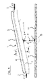
- the moving walk is generally designated 1 (see FIG. 1).
- the term moving walk is used as a synonym for bridge-like means of transport (moving walks) or stair-like means of transport (escalators), such as those used in passenger or object transport.
- the invention is applicable to both escalators, which are arranged obliquely and typically connect two or more floors to each other, as well as horizontally or obliquely arranged moving walks.
- the moving walkways according to the invention are characterized in that they comprise a supporting structure 7 which has at least one tension element 11 in the region between the two extremal ends of the supporting structure 7.
- This tension element 11 is mechanically connected at a first end to the supporting structure 7 and at a second end mechanically to a point of attachment.
- the traction element 11 is designed so that it exerts a tensile force F on the supporting structure 7, which acts at least partially in the direction of gravitational force.
- the tension member 11 replaces the suspension elements or supports of the prior art, even if this may sound questionable at first.
- the tension member 11 exerts a tensile force F on the structure 7, at least partially in the direction of gravity acts. If the moving walk 1 is unloaded, ie if there are no loads on the moving walk 1, this tensile load F ensures a defined single load on the structure 7. This single load causes a certain bending of the structure 7 in the direction of the tensile force F. Will now the moving walk burdened with a load, for example, when people enter the moving walkway, so the structure 7 will also want to bend in the direction of gravitational force.
- a load-related deflection of the structure 7 is reduced by a reduction in the resulting bias of the structure 7 deflection.
- the bias of the structure 7 is, as described, caused by one or more tension elements 11, which must be designed so that they reduce the effective acting tensile force F when loading the moving walk 1 (for example, by slackening of the pull rope).
- the interaction of the flexural rigidity of the structure 7 (and possibly the other supporting elements of the moving walk 1) and the expansion stiffness of the tension member 11 is coordinated so that with an increase in traffic load, the resulting computational deformation is the same size as the decrease in deformation due Simplified expressed, as initially postulated, thus a moving walk 1 is virtually "supported” by the amount of tensile force decrease .DELTA.F (Seilkraftab casserole) in the middle of the field.
- the virtual support force adapts depending on the dimensioning of the individual components in many areas automatically the amount of the current traffic load.
- the effective tensile force F of the tension member 11 is so in the dead weight of the moving walk 1 maximum and decreases with increasing load on the moving walk 1 (the pull rope is "limp").
- the device according to the invention with tension element can also be referred to as an "intelligent center support” or as a “virtual center support”.
- the effectively occurring deformation of the moving walk 1 under load, respectively the load-bearing elements of the moving walk 1, can be reduced to zero or almost zero.
- a moving walk 1 usually has on both sides of a longitudinal axis L a supporting structure 7, which is preferably constructed in the manner of a truss.
- the structure 7 is supported in the region of its two extremal ends.
- the moving walk 1 can connect two floors E1 and E2 together.
- supports can be provided to support the moving walk 1. In the figures, these supports are not shown.
- each traction means 11 is provided on both sides of the moving walk 1 in the embodiment shown.
- Each of the traction means 11 engages directly, or via a connecting element 9, on a lateral cheek of the structure 7.
- the moving walk 1 comprises a continuous treadmill or a rolling belt consisting of steps, the position of which is marked as 4 in FIG.
- Laterally optional balustrades 5 are provided with handrail 6.
- a connecting element 9 is provided at a lower edge 7.1 of the structure 7 or laterally on the cheek .
- a rope 8 for example a steel cable, attached.
- This rope 8 ends on the other side at a starting point 12.
- a connecting element can serve to attach the rope 8 to a floor 10, foundation, support or other point.
- the tension element 11 is substantially perpendicular to the ground 10. However, it can also be arranged obliquely, as long as the condition is met that at least a part of the tensile force F acts parallel to the gravitational force.
- the attachment point 12 is laterally below below the moving walk 1 on a wall or a column.
- FIG. 3 shows a detail B of the embodiment shown in FIGS. 1 and 2.
- the connecting element 9 is bolted to the structure 7, riveted or otherwise secured there.
- the cable 8 may be fastened to the connecting element 9 with an eyelet, as shown in FIG. 3, or by other means (for example with a clamping or screw connection). At the lower end of the rope 8 this is connected to a connecting element 12.
- the connecting element 12 is bolted to the bottom 10, riveted or otherwise secured there.
- the connecting element 12 may also be cast in the ground 10.
- the tension is on the rope 8 through turnbuckles, sleeves with links u. Right-hand thread, or similar, or by turning the tie rod (Fig.1) by means of a special key and then countering the nut at the clevis.
- FIG. 4 shows a section B of a further embodiment.
- the connecting element 9 is bolted to the structure 7, riveted or otherwise secured there. It is a combination of a rope 8 and a tension spring 13 (spring) provided.
- the rope 8 is in this case shorter than in Fig. 3. It may be attached to the connecting element 9 with an eyelet, as shown in Fig. 4, or by other means (for example with a clamping or screw connection). At the lower end of the rope 8 this is connected to the tension spring 13.
- a connecting element 12 secures the tension spring 13 at the bottom 10.
- the connecting element 12 can be screwed, riveted or otherwise secured.
- the connecting element 12 may also be cast in the ground 10.
- FIG. 5 shows a section B of a further embodiment.
- the connecting element 9 is bolted to the structure 7, riveted or otherwise secured there. It is a combination of a rod 14 and a tension spring 13 (standing spring) is provided.
- the rod 14 may be secured to the connector 9 with an eyelet as shown in FIG. 5 or by other means (for example with a clamp or screw connection). At the lower end of the rod 14 this is connected to the tension spring 13.
- a connecting element 12 secures the tension spring 13 at the bottom 10.
- the connecting element 12 can be screwed, riveted or otherwise secured.
- the connecting element 12 may also be cast in the ground 10. Particularly advantageous is an embodiment in which the spring force of the upright spring is adjustable by mechanical means.
- the invention can be, as emphasized at the beginning, apply not only on moving walks but also on escalators.
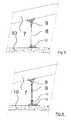
- the tension element can be arranged centrally, halfway between the two extremal ends of the structure 7. But it is also possible to arrange the tension element 11 at a different location. It is also possible to provide more than just one pulling element 11.
- a tension element 11 is provided per cheek of the structure 7 in order to achieve a symmetrical load, respectively bias.
- Fig. 6 an approach is shown very schematically, in which only a tension element 11 sits centrally between the two cheeks of the structure 7.
- the tension member 11 is then attached to a cross member 15 which connects the two cheeks.
- Fig. 7 an approach is shown very schematically, in which the tension member 11 has two tension cables 8, which are centrally summarized by an eyelet 16 or a clamp together (two-strand bracing in Y-type). Preferably, this tension element 11 is then attached to the cheeks of the structure 7.
- the supporting structure 7 is preferably made reinforced in the field of force application.
- moving walks or escalators can be used at fairs, exhibitions, stations and so on application to bridge great distances.
Landscapes
- Escalators And Moving Walkways (AREA)
Abstract
Description
- Die vorliegende Erfindung betrifft eine Fahrtreppe oder einen Fahrsteig mit Tragwerk, das im Bereich seiner extremalen Enden abgestützt ist.
- Das Tragwerk einer herkömmlichen Fahrtreppe bzw. eines herkömmlichen Fahrsteigs kann nur eine bestimmte Spannweite überbrücken. Es ist daher schon seit langem bekannt (siehe die Fig. 3 der
DE 709291 C1 aus dem Jahre 1941), das Tragwerk durch eine Säule in der Mitte zu unterstützen. Eine solche Säule wird typischerweise als Mittellager bezeichnet. Will man noch längere Fahrtreppen bzw. Fahrsteige bauen, sind mehrere Säulen zur Unterstützung notwendig. Es gibt feste und verstellbare Mittellager. - Nachteilig ist dabei, dass derartige Mittellager mechanisch komplex und unter Umständen auch schwer sind. Zusätzlich ist die Montage recht aufwendig. Ausserdem sind in gewissen Situationen Mittellager nach dem Stand der Technik aus ästhetischen Gesichtspunkten nicht erwünscht.
- Andere Tragwerke werden hingegen von oben her durch eine Aufhängung unterstützt. Ein entsprechendes Beispiel ist aus der
EP-Patentanmeldung EP 1 270 490 A1 bekannt. Diese Art der Aufhängung erlaubt es den Raum unterhalb des Tragwerks von störenden Elementen frei zu halten, es braucht aber im Bereich oberhalb der Fahrtreppe bzw. des Fahrsteigs zusätzlichen Raum. Ausserdem muss für die Aufhängung ein aufwendiges Fundament vorgesehen werden. - Es ist Aufgabe der vorliegenden Erfindung, eine Fahrtreppe bzw. einen Fahrsteig der eingangs genannten Art bereit zu stellen, die/der ohne Stützen oder aufwendiges Fundament auskommt und trotzdem grössere Spannweiten als bisher üblich überbrücken kann.
- Es ist eine weitere Aufgabe der Erfindung, eine Fahrtreppe bzw. einen Fahrsteig der eingangs genannten Art bereit zu stellen, die/der auch im Falle eines Erdbebens stabil ist.
- Diese Aufgabe wird bei einem Fahrsteig bzw. einer Fahrtreppe der eingangs genannten Art erfindungsgemäss dadurch gelöst, dass das Tragwerk des Fahrsteigs bzw. der Fahrtreppe im Bereich zwischen beiden extremalen Enden mindestens ein Zugelement aufweist. Das Zugelement ist an einem ersten Ende mechanisch mit dem Tragwerk und an einem zweiten Ende mit einem Ansatzpunkt, zum Beispiel im Bodenbereich unterhalb des Fahrsteigs oder der Fahrtreppe, verbunden. Das Zugelement ist gemäss Erfindung so ausgeführt ist, dass es eine Zugkraft auf das Tragwerk ausübt, die mindestens teilweise in Richtung der Erdanziehungskraft wirkt.
- Dieses Zugelement dient bei geeigneter Dimensionierung und Ausführung als eine Art "virtuelles Mittellager".
- Es wird als ein Vorteil der Erfindung angesehen, dass sich das erfindungsgemässe "virtuelle Mittellager" einfach und schnell montieren lässt. Ausserdem werden je nach Ausführungsform nur wenige Bauteile gebraucht, die alle in der Herstellung einfach und daher auch kostengünstig sind.
- Ausserdem wird durch die Vorspannung, die vom Zugelement vorgegeben wird die Schwingungs- oder Vibrationsneigung des Fahrsteigs reduziert. Ungünstige Resonanzen können unterdrückt werden.
- Falls ein Zugelement mit Stehfeder zum Einsatz kommt, kann die Feder zur Stabilisierung dienen.
- Ein besonderer Vorteil der Erfindung wird darin gesehen, dass der Fahrsteig, bzw. die Fahrtreppe wesentlich erdbebentauglicher ist als bisherige Anordnungen. Oft liegt der Fahrsteig, bzw. die Fahrtreppe an einem oder an beiden extremalen Enden (wo üblicherweise die Auflager vorgesehen sind) lose, oder in einer Führung, auf den Stockwerkböden auf. Durch die Zugkraft des Zugelements wird der Fahrsteig, bzw. die Fahrtreppe fixiert und auch im Falle eines Erdbebens nun trotzdem sicher gehalten. Das vorgespannte Seil im Falle eines Erdbebens hat eine gewisse durchbiegungs- und spannungsbegrenzende Wirkung.
- Durch die Verwendung eines Zugelements ergibt sich ausserdem ein elegantes, schlankes Aussehen.
- Der Raum unterhalb einer Fahrtreppe oder eines Fahrsteigs kann besser genutzt werden. Eventuell kann das Zugelement in einen Unterbau integriert werden.
- Ein weiterer Vorteil dieser Konstruktion ist, dass man, wenn es gewünscht wird, keine Druckkräfte ins Fundament (mit Mittellager) einleitet, sondern Zugkräfte, also beispielsweise die Geschoßdecke nicht zusätzlich belastet wird, sondern der Gewichtskraft entgegenwirkt wird.
- Der Hauptnutzen ist die, fast vollständige oder zumindest teilweise Kompensation der Durchbiegung unter Nutzlast. Dadurch kann man weitgespannte, schlanke Tragwerke realisieren. Die Spannseile werden dabei optisch kaum wahrgenommen.
- Weitere Merkmale und Vorteile der Erfindung gehen aus der nachstehenden Beschreibung zweier Ausführungsbeispiele anhand der Zeichnungen hervor. Es zeigen:
- Fig. 1 einen erfindungsgemässen Fahrsteig mit mittig angeordneter Zugvorrichtung;
- Fig. 2 einen Querschnitt durch einen erfindungsgemässen Fahrsteig mit zwei mittig angeordneten Zugvorrichtungen;
- Fig. 3 eine Detailansicht einer ersten erfindungsgemässen Zugvorrichtung;
- Fig. 4 eine Detailansicht einer zweiten erfindungsgemässen Zugvorrichtung;
- Fig. 5 eine Detailansicht einer dritten erfindungsgemässen Zugvorrichtung;
- Fig. 6 einen Querschnitt durch einen erfindungsgemässen Fahrsteig mit einer mittig angeordneten Zugvorrichtung;
- Fig. 7 einen Querschnitt durch einen erfindungsgemässen Fahrsteig mit zwei mittig angeordneten Zugvorrichtungen, die Y-förmig zusammengefasst sind.
- Der Fahrsteig ist allgemein mit 1 (siehe Fig. 1) bezeichnet. Der Begriff Fahrsteig wird als Synonym verwendet für brückenartige Transportmittel (Fahrsteige) oder treppenartige Transportmittel (Fahrtreppen), wie sie bei der Personen- oder Objektbeförderung zum Einsatz kommen. Die Erfindung ist sowohl auf Fahrtreppen, die schräg angeordnet sind und typischerweise zwei oder mehr Stockwerke miteinander verbinden, als auch auf horizontal oder schräg angeordnete Fahrsteige anzuwenden.
- Die erfindungsgemässen Fahrsteige zeichnen sich dadurch aus, dass sie ein Tragwerk 7 umfassen, das im Bereich zwischen den beiden extremalen Enden des Tragwerks 7 mindestens ein Zugelement 11 aufweist. Dieses Zugelement 11 ist an einem ersten Ende mechanisch mit dem Tragwerk 7 und an einem zweiten Ende mechanisch mit einem Ansatzpunkt verbunden. Das Zugelement 11 ist so ausgeführt, dass es eine Zugkraft F auf das Tragwerk 7 ausübt, die mindestens teilweise in Richtung der Erdanziehungskraft wirkt.
- Bevor einzelne Ausführungsformen beschrieben werden, wird die Wirkungsweise des Zugelements 11 beschrieben. Vereinfacht ausgedrückt ersetzt das Zugelement 11 die Tragmittel bzw. Stützen des Standes der Technik, auch wenn dies im ersten Moment fragwürdig klingen mag. Das Zugelement 11 übt eine Zugkraft F auf das Tragwerk 7 aus, die mindestens teilweise in Richtung der Erdanziehungskraft wirkt. Falls der Fahrsteig 1 unbelastet ist, d.h. falls sich keine Lasten auf dem Fahrsteig 1 befinden, sorgt diese Zugbelastung F für eine definierte Einzellast am Tragwerk 7. Diese Einzellast bewirkt eine gewisse Verbiegung des Tragwerks 7 in Richtung der Zugkraft F. Wird nun der Fahrsteig 1 mit einer Last belastet, zum Beispiel wenn Personen den Fahrsteig betreten, so wird sich das Tragwerk 7 zusätzlich in Richtung der Erdanziehungskraft durchbiegen wollen. Eine solche zusätzliche Durchbiegung führt aber gleichzeitig am Zugelement 11 zu einer Abnahme der effektiven Zugkraft F (im Falle eines als Zugelement dienenden Zugseils zum Beispiel wird dieses Zugseil "schlaffer"). Nimmt die effektive Zugkraft F ab, so wird das Tragwerk 7 des Fahrsteigs 1 gegenüber dem lastfreien Zustand entlastet. Als Folge will sich das Tragwerk 7 des Fahrsteigs 1 also heben. Diese beiden Effekte kompensieren sich, wenn die Elemente des Fahrsteigs 1 entsprechend dimensioniert sind, d.h., die durch Last auf dem Fahrsteig 1 ausgelöste in Richtung Erdanziehung gerichtete Kraft wird mindestens teilweise durch die Rückstellkraft des Tragwerks 7 reduziert, die entsteht sobald die effektive Zugkraft F des Zugelements 11 nachlässt.
- Mit anderen Worten ausgedrückt, wird eine belastungsbedingte Durchbiegung des Tragwerks 7 durch eine Reduzierung der durch Vorspannung des Tragwerks 7 entstandenen Durchbiegung reduziert. Die Vorspannung des Tragwerks 7 wird, wie beschrieben, durch eines oder mehrere Zugelemente 11 bewirkt, die so ausgeführt sein müssen, dass sie bei Belastung des Fahrsteigs 1 die effektive wirkende Zugkraft F reduzieren (zum Beispiel durch Erschlaffen des Zugseils).
- Vorzugsweise wird das Zusammenwirken der Biegesteifigkeit des Tragwerks 7 (und gegebenenfalls der anderen tragenden Elemente des Fahrsteigs 1) und die Dehnungssteifigkeit des Zugelements 11 so aufeinander abgestimmt, dass bei einer Zunahme der Verkehrsbelastung die daraus resultierende rechnerische Verformung gleich gross wird wie die Abnahme der Verformung infolge der reduzierten Zugkraft (als effektive Zugkraft bezeichnet) des Zugelements 11. Vereinfacht ausgedrückt, wie eingangs postuliert, wird somit ein Fahrsteig 1 durch den Betrag der Zugkraftabnahme ΔF(Seilkraftabnahme) in der Feldmitte virtuell "gestützt". Die virtuelle Stützkraft passt sich je nach Dimensionierung der einzelnen Komponenten in weiten Bereichen automatisch der Höhe der momentanen Verkehrsbelastung an.
- Die effektive Zugkraft F des Zugelements 11 ist also im Eigengewichtszustand des Fahrsteigs 1 maximal und nimmt mit zunehmender Belastung des Fahrsteigs 1 ab (das Zugseil wird "schlaff"). Man kann somit die erfindungsgemässe Vorrichtung mit Zugelement auch als ein "intelligentes Mittelauflager" oder ais "virtuelles Mittelauflager" bezeichnen.
- Bei geeigneter Dimensionierung der einzelnen Komponenten kann die effektiv auftretende Verformung des Fahrsteigs 1 bei Belastung, respektive der tragenden Elemente des Fahrsteigs 1, auf Null oder nahezu Null reduziert werden.
- Die Anwendung dieser Erfindung wird im Folgenden anhand verschiedener Ausführungsformen beschrieben.
- Ein Fahrsteig 1 weist üblicherweise zu beiden Seiten einer Längsachse L ein Tragwerk 7 auf, welches vorzugsweise in der Art eines Fachwerks aufgebaut ist. Das Tragwerk 7 ist im Bereich seiner beiden extremalen Enden abgestützt. Wie in Fig. 1 angedeutet, kann der Fahrsteig 1 zwei Stockwerke E1 und E2 miteinander verbinden. Im Bereich der Übergänge 2 bzw. 3 zu diesen Stockwerken können zum Beispiel Auflager vorgesehen sein, um den Fahrsteig 1 zu unterstützen. In den Figuren sind diese Auflager nicht gezeigt.
- Gemäss Fig. 1 und 2 ist in der gezeigten Ausführungsform zu beiden Seiten des Fahrsteiges 1 je ein Zugmittel 11 vorgesehen. Jedes der Zugmittel 11 greift unmittelbar, oder über ein Verbindungselement 9, an einer seitlichen Wange des Tragwerks 7 an.
- Im Folgenden sind weitere Details der in den Figuren 1 und 2 gezeigten Ausführungsform beschrieben. Der Fahrsteig 1 umfasst ein kontinuierliches Laufband oder ein aus Stufen bestehendes Rollband, dessen Lage in Fig. 1 als 4 gekennzeichnet ist. Seitlich sind optional Balustraden 5 mit Handlauf 6 vorgesehen. An einer unteren Kante 7.1 des Tragwerks 7 oder seitlich an der Wange ist je ein Verbindungselement 9 vorgesehen. An dem Verbindungselement 9 ist ein Seil 8, zum Beispiel ein Stahlseil, befestigt. Dieses Seil 8 endet auf der anderen Seite bei einem Ansatzpunkt 12. Auch hier kann ein Verbindungselement dazu dienen, um das Seil 8 an einem Boden 10, Fundament, Träger oder anderem Punkt zu befestigen.
- Im gezeigten Beispiel "steht" das Zugelement 11 im Wesentlichen senkrecht auf dem Boden 10. Es kann aber auch schräg angeordnet sein, solange die Bedingung erfüllt ist, dass mindestens ein Teil der Zugkraft F parallel zur Erdanziehungskraft wirkt. In einer besonderen Ausführungsform befindet sich der Ansatzpunkt 12 seitlich unterhalb neben dem Fahrsteig 1 an einer Wand oder einer Säule.
- In Fig. 3 ist ein Ausschnitt B der in den Figuren 1 und 2 gezeigten Ausführungsform zu erkennen. Das Verbindungselement 9 ist mit dem Tragwerk 7 verschraubt, vernietet oder anderweitig dort befestigt. Das Seil 8 kann mit einer Öse, wie in Fig. 3 gezeigt, oder mit anderen Mitteln (zum Beispiel mit einer Klemm- oder Schraubverbindung) an dem Verbindungselement 9 befestigt sein. Am unteren Ende des Seils 8 ist dieses mit einem Verbindungselement 12 verbunden. Das Verbindungselement 12 ist mit dem Boden 10 verschraubt, vernietet oder anderweitig dort befestigt. Das Verbindungselement 12 kann auch im Boden 10 eingegossen sein.
- Die Zugsspannung wird auf das Seil 8 durch Spannschlösser, Muffen mit Links u. Rechtsgewinde, oder ähnlichem gegeben,
bzw. durch Verdrehen der Zugstange (Fig.1) mittels eines Spezialschlüssels und anschließenden Kontern der Mutter beim Gabelkopf. - Es wird soweit vorgespannt bis eine definierte Durchbiegung gemessen wird.
In Fig. 4 ist ein Ausschnitt B einer weiteren Ausführungsform zu erkennen. Das Verbindungselement 9 ist mit dem Tragwerk 7 verschraubt, vernietet oder anderweitig dort befestigt. Es ist eine Kombination aus einem Seil 8 und einer Zugfeder 13 (Stehfeder) vorgesehen. Das Seil 8 ist in diesem Fall kürzer als in Fig. 3. Es kann mit einer Öse, wie in Fig. 4 gezeigt, oder mit anderen Mitteln (zum Beispiel mit einer Klemm- oder Schraubverbindung) an dem Verbindungselement 9 befestigt sein. Am unteren Ende des Seils 8 ist dieses mit der Zugfeder 13 verbunden. Ein Verbindungselement 12 befestigt die Zugfeder 13 am Boden 10. Dort kann das Verbindungselement 12 verschraubt, vernietet oder anderweitig befestigt sein. Das Verbindungselement 12 kann auch im Boden 10 eingegossen sein. - Es ist ein Vorteil der Anordnung mit Zugseil 8 und Zugfeder 13, dass man die Länge des Seils 8 frei wählen kann. Bei geeigneter Wahl der Seil/Federkombination kann man den Effekt der temperaturbedingten Ausdehnung des Seils 8 in den Griff bekommen. Besonders vorteilhaft ist eine Ausführungsform bei der die Federkraft der Stehfeder durch mechanische Mittel verstellbar ist.
- In Fig. 5 ist ein Ausschnitt B einer weiteren Ausführungsform zu erkennen. Das Verbindungselement 9 ist mit dem Tragwerk 7 verschraubt, vernietet oder anderweitig dort befestigt. Es ist eine Kombination aus einem Stab 14 und einer Zugfeder 13 (Stehfeder) vorgesehen. Der Stab 14 kann mit einer Öse, wie in Fig. 5 gezeigt, oder mit anderen Mitteln (zum Beispiel mit einer Klemm- oder Schraubverbindung) an dem Verbindungselement 9 befestigt sein. Am unteren Ende des Stabs 14 ist dieses mit der Zugfeder 13 verbunden. Ein Verbindungselement 12 befestigt die Zugfeder 13 am Boden 10. Dort kann das Verbindungselement 12 verschraubt, vernietet oder anderweitig befestigt sein. Das Verbindungselement 12 kann auch im Boden 10 eingegossen sein. Besonders vorteilhaft ist eine Ausführungsform bei der die Federkraft der Stehfeder durch mechanische Mittel verstellbar ist.
- Die Erfindung lässt sich, wie eingangs betont, nicht nur auf Fahrsteige sondern auch auf Fahrtreppen anwenden.
- Je nach Bedarf kann das Zugelement mittig, auf halber Strecke zwischen den beiden extremalen Enden des Tragwerks 7, angeordnet sein. Es ist aber auch möglich das Zugelement 11 an einer anderen Stelle anzuordnen. Es können auch mehr als nur ein Zugelement 11 vorgesehen werden.
- In Fig. 2 kann man erkennen, dass ein Zugelement 11 pro Wange des Tragwerks 7 vorgesehen ist, um eine symmetrische Belastung, respektive Vorspannung zu erzielen.
- In Fig. 6 ist ein Ansatz stark schematisiert dargestellt, bei dem nur ein Zugelement 11 mittig zwischen den beiden Wangen des Tragwerks 7 sitzt. Vorzugsweise wird das Zugelement 11 dann an einem Querträger 15 befestigt, der die beiden Wangen verbindet.
- In Fig. 7 ist ein Ansatz stark schematisiert dargestellt, bei dem das Zugelement 11 zwei Zugseile 8 aufweist, die mittig durch eine Öse 16 oder eine Klammer zusammen gefasst sind (zwei-strangige Abspannung in Y-Ausführung). Vorzugsweise wird dieses Zugelement 11 dann an den Wangen des Tragwerks 7 befestigt.
- Um die durch die Zugelemente 11 verursachten Kräfte aufnehmen zu können, ist das Tragwerk 7 vorzugsweise im Bereich der Krafteinleitung verstärkt ausgeführt.
- Selbstverständlich kann je nach Stärke der Zugkraft F im Bodenbereich ein entsprechend tiefes, betoniertes Fundament notwendig sein.
- Durch optionale Diagonalstreben, wie in der Patentschrift
EP 0 866 019 B1 beschrieben, ergibt sich eine zusätzliche seitliche Stabilität. - Erfindungsgemässe Fahrsteige bzw. Fahrtreppen können bei Messen, Ausstellungen, Bahnhöfen und so weiter Anwendung finden, um grosse Distanzen zu überbrücken.
Claims (8)
- Fahrtreppe oder Fahrsteig (1) mit mindestens einem Tragwerk (7), das im Bereich seiner extremalen Enden abgestützt ist, dadurch gekennzeichnet, dass das Tragwerk (7) im Bereich zwischen den beiden extremalen Enden mindestens ein Zugelement (11) aufweist, das an einem ersten Ende mechanisch mit dem Tragwerk (7) und an einem zweiten Ende mit einem Ansatzpunkt (12) verbunden ist, wobei das Zugelement (11) so ausgeführt ist, dass es eine Zugkraft (F) auf das Tragwerk (7) ausübt, die mindestens teilweise in Richtung der Erdanziehungskraft wirkt.
- Fahrtreppe oder Fahrsteig (1) nach Anspruch 1, dadurch gekennzeichnet, dass das Zugelement (11) zur virtuellen Abstützung des Tragwerks (7) dient.
- Fahrtreppe oder Fahrsteig (1) nach Anspruch 1 oder 2, dadurch gekennzeichnet, dass das Zugelement (11) das Tragwerk (7), oder ein Teil des Tragwerks (7), durch die Zugkraft (F) vorspannt.
- Fahrtreppe oder Fahrsteig (1) nach Anspruch 3, dadurch gekennzeichnet, dass das Zugelement (11) sich entspannt, wenn der Fahrsteig (1) belastet wird, wobei sich durch diese Entspannung eine Reduktion der Zugkraft (F) ergibt.
- Fahrtreppe oder Fahrsteig (1) nach einem der vorhergehenden Ansprüche, dadurch gekennzeichnet, dass zwei Zugelemente (11) vorgesehen sind, die symmetrisch zu einer Längsachse (L) der Fahrtreppe oder des Fahrsteigs (1) angeordnet sind.
- Fahrtreppe oder Fahrsteig (1) nach einem der vorhergehenden Ansprüche, dadurch gekennzeichnet, dass das Zugelement (11)- ein Seil (8), vorzugsweise ein Stahlseil, und/oder- eine Zugfeder (13), und/oder- einen Stab (14) umfasst.
- Fahrtreppe nach einem der vorhergehenden Ansprüche, dadurch gekennzeichnet, dass die Fahrtreppe schräg angeordnet ist und vorzugsweise zwei Stockwerke (E1, E2) miteinander verbindet.
- Fahrsteig (1) nach einem der vorhergehenden Ansprüche, dadurch gekennzeichnet, dass der Fahrsteig (1) horizontal oder schräg angeordnet ist.
Priority Applications (1)
| Application Number | Priority Date | Filing Date | Title |
|---|---|---|---|
| EP06112648A EP1714935B1 (de) | 2005-04-19 | 2006-04-13 | Fahrtreppe oder Fahrsteig mit seilartiger Abspannung |
Applications Claiming Priority (2)
| Application Number | Priority Date | Filing Date | Title |
|---|---|---|---|
| EP05103151 | 2005-04-19 | ||
| EP06112648A EP1714935B1 (de) | 2005-04-19 | 2006-04-13 | Fahrtreppe oder Fahrsteig mit seilartiger Abspannung |
Publications (2)
| Publication Number | Publication Date |
|---|---|
| EP1714935A1 true EP1714935A1 (de) | 2006-10-25 |
| EP1714935B1 EP1714935B1 (de) | 2008-11-05 |
Family
ID=35241100
Family Applications (1)
| Application Number | Title | Priority Date | Filing Date |
|---|---|---|---|
| EP06112648A Expired - Lifetime EP1714935B1 (de) | 2005-04-19 | 2006-04-13 | Fahrtreppe oder Fahrsteig mit seilartiger Abspannung |
Country Status (9)
| Country | Link |
|---|---|
| US (1) | US7426989B2 (de) |
| EP (1) | EP1714935B1 (de) |
| JP (1) | JP2006298646A (de) |
| CN (1) | CN100554127C (de) |
| AT (1) | ATE413357T1 (de) |
| BR (1) | BRPI0601278B1 (de) |
| CA (1) | CA2543478C (de) |
| DE (1) | DE502006001970D1 (de) |
| ES (1) | ES2317424T3 (de) |
Families Citing this family (7)
| Publication number | Priority date | Publication date | Assignee | Title |
|---|---|---|---|---|
| DE502006006772D1 (de) * | 2005-12-07 | 2010-06-02 | Inventio Ag | Fahrsystemaufnehmer. |
| CN101955120A (zh) * | 2010-04-28 | 2011-01-26 | 江南嘉捷电梯股份有限公司 | 自动人行道上的支撑结构 |
| JP2013189298A (ja) * | 2012-03-14 | 2013-09-26 | Hitachi Ltd | 乗客コンベア |
| CN104411616B (zh) * | 2012-06-21 | 2016-05-18 | 三菱电机株式会社 | 乘客输送机 |
| CN104229612B (zh) * | 2013-06-07 | 2017-04-12 | 通力股份公司 | 桁架装置及自动扶梯或自动人行道 |
| CN107922167B (zh) * | 2015-08-11 | 2019-07-05 | 三菱电机株式会社 | 乘客输送机的桁架支撑装置 |
| CN112193976B (zh) * | 2020-09-30 | 2022-11-01 | 宁波宏大电梯有限公司 | 一种大跨距无支撑自动扶梯 |
Citations (6)
| Publication number | Priority date | Publication date | Assignee | Title |
|---|---|---|---|---|
| DE709291C (de) * | 1937-06-30 | 1941-08-12 | Mecc Stigler Off | Fahrtreppe |
| JPS63282093A (ja) * | 1987-05-14 | 1988-11-18 | 三菱電機株式会社 | 乗客コンベアの中間支持装置 |
| EP0866019A1 (de) * | 1997-03-17 | 1998-09-23 | Inventio Ag | Fahrtreppe oder Fahrsteig mit Unterspannung |
| EP1074507A1 (de) * | 1999-08-06 | 2001-02-07 | Inventio Ag | Tragkonstruktion für lange Fahrtreppen und Fahrsteige |
| EP1270490A1 (de) * | 2001-06-29 | 2003-01-02 | Inventio Ag | Konstruktion für Fahrtreppe oder Fahrsteig mit grosser Spannweite |
| EP1273548A1 (de) * | 2001-07-02 | 2003-01-08 | Inventio Ag | Fahrtreppe oder Fahrsteig mit Tragwerk |
Family Cites Families (13)
| Publication number | Priority date | Publication date | Assignee | Title |
|---|---|---|---|---|
| BE757450A (de) * | 1969-10-13 | 1971-03-16 | Goodyear Tire & Rubber | |
| US3861514A (en) * | 1971-09-27 | 1975-01-21 | Robin D Ling | Straddle-form ski lift |
| US3991877A (en) * | 1975-02-20 | 1976-11-16 | Westinghouse Electric Corporation | Transportation apparatus |
| US4413719A (en) * | 1981-05-28 | 1983-11-08 | White Carl J | Method and apparatus for entrapment prevention and lateral guidance in passenger conveyor systems |
| JPS59138587A (ja) * | 1983-01-25 | 1984-08-09 | 三菱電機株式会社 | 乗客コンベヤの安全装置 |
| GB2163399B (en) * | 1984-08-22 | 1988-06-02 | Hitachi Ltd | Passenger conveyor |
| US5421076A (en) * | 1993-12-23 | 1995-06-06 | Otis Elevator Company | Method for assembling a balustrade for a people moving device using an adjustable assembly jig |
| JPH1087248A (ja) * | 1996-09-20 | 1998-04-07 | Mitsubishi Heavy Ind Ltd | 可変速式コンベア |
| MY118185A (en) * | 1997-03-17 | 2004-09-30 | Inventio Ag | Escalator or walkway provided with a stiffening element. |
| JP4824157B2 (ja) * | 1999-08-06 | 2011-11-30 | インベンテイオ・アクテイエンゲゼルシヤフト | 長いエスカレータと動く歩道の支持構造体 |
| US6685001B2 (en) * | 2001-06-29 | 2004-02-03 | Inventio Ag | Escalator or moving walkway with overhead support |
| CA2390783C (en) * | 2001-07-02 | 2009-12-29 | Inventio Ag | Escalator or moving walkway with support structure |
| US6637580B1 (en) * | 2002-12-05 | 2003-10-28 | Terryle L. Sneed | Telescoping escalator seismic restraint |
-
2006
- 2006-04-06 JP JP2006104884A patent/JP2006298646A/ja not_active Withdrawn
- 2006-04-13 CA CA2543478A patent/CA2543478C/en not_active Expired - Fee Related
- 2006-04-13 AT AT06112648T patent/ATE413357T1/de not_active IP Right Cessation
- 2006-04-13 ES ES06112648T patent/ES2317424T3/es not_active Expired - Lifetime
- 2006-04-13 DE DE502006001970T patent/DE502006001970D1/de not_active Expired - Lifetime
- 2006-04-13 EP EP06112648A patent/EP1714935B1/de not_active Expired - Lifetime
- 2006-04-18 CN CNB2006100736773A patent/CN100554127C/zh not_active Expired - Fee Related
- 2006-04-18 BR BRPI0601278-7A patent/BRPI0601278B1/pt not_active IP Right Cessation
- 2006-04-19 US US11/407,316 patent/US7426989B2/en not_active Expired - Fee Related
Patent Citations (6)
| Publication number | Priority date | Publication date | Assignee | Title |
|---|---|---|---|---|
| DE709291C (de) * | 1937-06-30 | 1941-08-12 | Mecc Stigler Off | Fahrtreppe |
| JPS63282093A (ja) * | 1987-05-14 | 1988-11-18 | 三菱電機株式会社 | 乗客コンベアの中間支持装置 |
| EP0866019A1 (de) * | 1997-03-17 | 1998-09-23 | Inventio Ag | Fahrtreppe oder Fahrsteig mit Unterspannung |
| EP1074507A1 (de) * | 1999-08-06 | 2001-02-07 | Inventio Ag | Tragkonstruktion für lange Fahrtreppen und Fahrsteige |
| EP1270490A1 (de) * | 2001-06-29 | 2003-01-02 | Inventio Ag | Konstruktion für Fahrtreppe oder Fahrsteig mit grosser Spannweite |
| EP1273548A1 (de) * | 2001-07-02 | 2003-01-08 | Inventio Ag | Fahrtreppe oder Fahrsteig mit Tragwerk |
Also Published As
| Publication number | Publication date |
|---|---|
| CA2543478A1 (en) | 2006-10-19 |
| CN1854056A (zh) | 2006-11-01 |
| HK1098116A1 (zh) | 2007-07-13 |
| BRPI0601278A (pt) | 2006-12-19 |
| EP1714935B1 (de) | 2008-11-05 |
| US7426989B2 (en) | 2008-09-23 |
| CA2543478C (en) | 2014-04-01 |
| US20060254878A1 (en) | 2006-11-16 |
| CN100554127C (zh) | 2009-10-28 |
| BRPI0601278B1 (pt) | 2018-02-14 |
| ATE413357T1 (de) | 2008-11-15 |
| ES2317424T3 (es) | 2009-04-16 |
| JP2006298646A (ja) | 2006-11-02 |
| DE502006001970D1 (de) | 2008-12-18 |
Similar Documents
| Publication | Publication Date | Title |
|---|---|---|
| DE10315989B4 (de) | Spannsystem für einen Mobil-Teleskopkran | |
| DE102015007636B4 (de) | Gitterstück für einen Gitterausleger, Gitterausleger sowie Kran | |
| EP3274288B1 (de) | Kranturm | |
| EP1714935B1 (de) | Fahrtreppe oder Fahrsteig mit seilartiger Abspannung | |
| EP0633214A2 (de) | Kurvenlose Schienenanordnung für den von einem Seil gezogenen Laufwagen eines stationären Schrägaufzugs | |
| EP2823860B1 (de) | Personensicherungssystem | |
| DE60308261T2 (de) | Selbsttragender Gitterträger für die Herstellung von Stahlbetonverbundträgern | |
| EP3319898B1 (de) | Turmkran | |
| DE202016105627U1 (de) | Aufzug für kleine Schachtabmessungen | |
| EP0685608B1 (de) | Stahlbetonfertigbauteil | |
| DE19831026B4 (de) | Tragende Seilkonstruktion | |
| DE10316405B4 (de) | Turmbauwerk | |
| EP2261162A1 (de) | Tragmittelendverbindung für eine Aufzugsanlage | |
| DE19708681C1 (de) | Vorrichtung zur Anordnung eines Hilfsauslegers an einen Teleskopkran | |
| DE102023113570B3 (de) | Spannsystem für eine Umlenkrolle eines Umlaufseils einer Wasserskianlage, Wasserskianlage und Verfahren | |
| DE2818993C2 (de) | Vorgespannte Tragkonstruktion, insbesondere für hohe Turmkrone | |
| EP1273548B1 (de) | Fahrtreppe oder Fahrsteig mit Tragwerk | |
| EP1270490B1 (de) | Konstruktion für Fahrtreppe oder Fahrsteig mit grosser Spannweite | |
| AT62332B (de) | Einrichtung zum Verspannen von Ausschubmasten, Auslegern oder dgl. mittels nach zwei oder mehreren Richtungen verlaufenden, an dem oberen Ende des Mastes oder dgl. befestigen, von Trommeln ablaufenden Zugorganen und zum Abstützen des Fahrgestelles derartiger Konstruktionen. | |
| DE2728474B2 (de) | Biegesteifer Rahmenkörper | |
| DE2329368A1 (de) | Vorbeanspruchter traeger | |
| DE9318732U1 (de) | Struktur für eine Konstruktion, wie Halle, Innenzelt, Zelt o.dgl. | |
| DE970175C (de) | Verfahren zum Herstellen einer teilverankerten oder voll in sich verankerten Haengebruecke und nach diesem Verfahren hergestellte Haengebruecke | |
| AT386445B (de) | Schalplatte mit einer schalhaut | |
| DE19981797B4 (de) | Überdachte Tribüne |
Legal Events
| Date | Code | Title | Description |
|---|---|---|---|
| PUAI | Public reference made under article 153(3) epc to a published international application that has entered the european phase |
Free format text: ORIGINAL CODE: 0009012 |
|
| AK | Designated contracting states |
Kind code of ref document: A1 Designated state(s): AT BE BG CH CY CZ DE DK EE ES FI FR GB GR HU IE IS IT LI LT LU LV MC NL PL PT RO SE SI SK TR |
|
| AX | Request for extension of the european patent |
Extension state: AL BA HR MK YU |
|
| 17P | Request for examination filed |
Effective date: 20070423 |
|
| AKX | Designation fees paid |
Designated state(s): AT BE BG CH CY CZ DE DK EE ES FI FR GB GR HU IE IS IT LI LT LU LV MC NL PL PT RO SE SI SK TR |
|
| REG | Reference to a national code |
Ref country code: HK Ref legal event code: DE Ref document number: 1098116 Country of ref document: HK |
|
| 17Q | First examination report despatched |
Effective date: 20070627 |
|
| GRAP | Despatch of communication of intention to grant a patent |
Free format text: ORIGINAL CODE: EPIDOSNIGR1 |
|
| GRAS | Grant fee paid |
Free format text: ORIGINAL CODE: EPIDOSNIGR3 |
|
| GRAA | (expected) grant |
Free format text: ORIGINAL CODE: 0009210 |
|
| AK | Designated contracting states |
Kind code of ref document: B1 Designated state(s): AT BE BG CH CY CZ DE DK EE ES FI FR GB GR HU IE IS IT LI LT LU LV MC NL PL PT RO SE SI SK TR |
|
| REG | Reference to a national code |
Ref country code: GB Ref legal event code: FG4D Free format text: NOT ENGLISH |
|
| REG | Reference to a national code |
Ref country code: CH Ref legal event code: EP |
|
| REG | Reference to a national code |
Ref country code: IE Ref legal event code: FG4D Free format text: LANGUAGE OF EP DOCUMENT: GERMAN |
|
| REF | Corresponds to: |
Ref document number: 502006001970 Country of ref document: DE Date of ref document: 20081218 Kind code of ref document: P |
|
| REG | Reference to a national code |
Ref country code: ES Ref legal event code: FG2A Ref document number: 2317424 Country of ref document: ES Kind code of ref document: T3 |
|
| LTIE | Lt: invalidation of european patent or patent extension |
Effective date: 20081105 |
|
| PG25 | Lapsed in a contracting state [announced via postgrant information from national office to epo] |
Ref country code: LT Free format text: LAPSE BECAUSE OF FAILURE TO SUBMIT A TRANSLATION OF THE DESCRIPTION OR TO PAY THE FEE WITHIN THE PRESCRIBED TIME-LIMIT Effective date: 20081105 |
|
| PG25 | Lapsed in a contracting state [announced via postgrant information from national office to epo] |
Ref country code: PL Free format text: LAPSE BECAUSE OF FAILURE TO SUBMIT A TRANSLATION OF THE DESCRIPTION OR TO PAY THE FEE WITHIN THE PRESCRIBED TIME-LIMIT Effective date: 20081105 Ref country code: LV Free format text: LAPSE BECAUSE OF FAILURE TO SUBMIT A TRANSLATION OF THE DESCRIPTION OR TO PAY THE FEE WITHIN THE PRESCRIBED TIME-LIMIT Effective date: 20081105 Ref country code: SI Free format text: LAPSE BECAUSE OF FAILURE TO SUBMIT A TRANSLATION OF THE DESCRIPTION OR TO PAY THE FEE WITHIN THE PRESCRIBED TIME-LIMIT Effective date: 20081105 Ref country code: IS Free format text: LAPSE BECAUSE OF FAILURE TO SUBMIT A TRANSLATION OF THE DESCRIPTION OR TO PAY THE FEE WITHIN THE PRESCRIBED TIME-LIMIT Effective date: 20090305 |
|
| REG | Reference to a national code |
Ref country code: HK Ref legal event code: GR Ref document number: 1098116 Country of ref document: HK |
|
| REG | Reference to a national code |
Ref country code: IE Ref legal event code: FD4D |
|
| PG25 | Lapsed in a contracting state [announced via postgrant information from national office to epo] |
Ref country code: BG Free format text: LAPSE BECAUSE OF FAILURE TO SUBMIT A TRANSLATION OF THE DESCRIPTION OR TO PAY THE FEE WITHIN THE PRESCRIBED TIME-LIMIT Effective date: 20090205 Ref country code: IE Free format text: LAPSE BECAUSE OF FAILURE TO SUBMIT A TRANSLATION OF THE DESCRIPTION OR TO PAY THE FEE WITHIN THE PRESCRIBED TIME-LIMIT Effective date: 20081105 Ref country code: EE Free format text: LAPSE BECAUSE OF FAILURE TO SUBMIT A TRANSLATION OF THE DESCRIPTION OR TO PAY THE FEE WITHIN THE PRESCRIBED TIME-LIMIT Effective date: 20081105 Ref country code: DK Free format text: LAPSE BECAUSE OF FAILURE TO SUBMIT A TRANSLATION OF THE DESCRIPTION OR TO PAY THE FEE WITHIN THE PRESCRIBED TIME-LIMIT Effective date: 20081105 Ref country code: RO Free format text: LAPSE BECAUSE OF FAILURE TO SUBMIT A TRANSLATION OF THE DESCRIPTION OR TO PAY THE FEE WITHIN THE PRESCRIBED TIME-LIMIT Effective date: 20081105 |
|
| PG25 | Lapsed in a contracting state [announced via postgrant information from national office to epo] |
Ref country code: PT Free format text: LAPSE BECAUSE OF FAILURE TO SUBMIT A TRANSLATION OF THE DESCRIPTION OR TO PAY THE FEE WITHIN THE PRESCRIBED TIME-LIMIT Effective date: 20090406 Ref country code: SE Free format text: LAPSE BECAUSE OF FAILURE TO SUBMIT A TRANSLATION OF THE DESCRIPTION OR TO PAY THE FEE WITHIN THE PRESCRIBED TIME-LIMIT Effective date: 20090205 |
|
| PLBE | No opposition filed within time limit |
Free format text: ORIGINAL CODE: 0009261 |
|
| STAA | Information on the status of an ep patent application or granted ep patent |
Free format text: STATUS: NO OPPOSITION FILED WITHIN TIME LIMIT |
|
| 26N | No opposition filed |
Effective date: 20090806 |
|
| BERE | Be: lapsed |
Owner name: INVENTIO A.G. Effective date: 20090430 |
|
| NLV4 | Nl: lapsed or anulled due to non-payment of the annual fee |
Effective date: 20091101 |
|
| REG | Reference to a national code |
Ref country code: SK Ref legal event code: MM4A Ref document number: E 4898 Country of ref document: SK Effective date: 20090413 |
|
| PG25 | Lapsed in a contracting state [announced via postgrant information from national office to epo] |
Ref country code: SK Free format text: LAPSE BECAUSE OF NON-PAYMENT OF DUE FEES Effective date: 20090413 Ref country code: NL Free format text: LAPSE BECAUSE OF NON-PAYMENT OF DUE FEES Effective date: 20091101 |
|
| PG25 | Lapsed in a contracting state [announced via postgrant information from national office to epo] |
Ref country code: MC Free format text: LAPSE BECAUSE OF NON-PAYMENT OF DUE FEES Effective date: 20090430 |
|
| PG25 | Lapsed in a contracting state [announced via postgrant information from national office to epo] |
Ref country code: BE Free format text: LAPSE BECAUSE OF NON-PAYMENT OF DUE FEES Effective date: 20090430 |
|
| PG25 | Lapsed in a contracting state [announced via postgrant information from national office to epo] |
Ref country code: AT Free format text: LAPSE BECAUSE OF NON-PAYMENT OF DUE FEES Effective date: 20090413 |
|
| PG25 | Lapsed in a contracting state [announced via postgrant information from national office to epo] |
Ref country code: GR Free format text: LAPSE BECAUSE OF FAILURE TO SUBMIT A TRANSLATION OF THE DESCRIPTION OR TO PAY THE FEE WITHIN THE PRESCRIBED TIME-LIMIT Effective date: 20090206 |
|
| REG | Reference to a national code |
Ref country code: CH Ref legal event code: PL |
|
| PG25 | Lapsed in a contracting state [announced via postgrant information from national office to epo] |
Ref country code: LI Free format text: LAPSE BECAUSE OF NON-PAYMENT OF DUE FEES Effective date: 20100430 Ref country code: CH Free format text: LAPSE BECAUSE OF NON-PAYMENT OF DUE FEES Effective date: 20100430 |
|
| PG25 | Lapsed in a contracting state [announced via postgrant information from national office to epo] |
Ref country code: LU Free format text: LAPSE BECAUSE OF NON-PAYMENT OF DUE FEES Effective date: 20090413 |
|
| PG25 | Lapsed in a contracting state [announced via postgrant information from national office to epo] |
Ref country code: HU Free format text: LAPSE BECAUSE OF FAILURE TO SUBMIT A TRANSLATION OF THE DESCRIPTION OR TO PAY THE FEE WITHIN THE PRESCRIBED TIME-LIMIT Effective date: 20090506 |
|
| PG25 | Lapsed in a contracting state [announced via postgrant information from national office to epo] |
Ref country code: CY Free format text: LAPSE BECAUSE OF FAILURE TO SUBMIT A TRANSLATION OF THE DESCRIPTION OR TO PAY THE FEE WITHIN THE PRESCRIBED TIME-LIMIT Effective date: 20081105 |
|
| REG | Reference to a national code |
Ref country code: ES Ref legal event code: GC2A Effective date: 20130905 |
|
| REG | Reference to a national code |
Ref country code: GB Ref legal event code: 746 Effective date: 20130903 |
|
| REG | Reference to a national code |
Ref country code: DE Ref legal event code: R084 Ref document number: 502006001970 Country of ref document: DE Effective date: 20130918 |
|
| REG | Reference to a national code |
Ref country code: FR Ref legal event code: PLFP Year of fee payment: 11 |
|
| PGFP | Annual fee paid to national office [announced via postgrant information from national office to epo] |
Ref country code: TR Payment date: 20160323 Year of fee payment: 11 |
|
| PGFP | Annual fee paid to national office [announced via postgrant information from national office to epo] |
Ref country code: CZ Payment date: 20160412 Year of fee payment: 11 Ref country code: FI Payment date: 20160413 Year of fee payment: 11 |
|
| REG | Reference to a national code |
Ref country code: FR Ref legal event code: PLFP Year of fee payment: 12 |
|
| PG25 | Lapsed in a contracting state [announced via postgrant information from national office to epo] |
Ref country code: CZ Free format text: LAPSE BECAUSE OF NON-PAYMENT OF DUE FEES Effective date: 20170413 Ref country code: FI Free format text: LAPSE BECAUSE OF NON-PAYMENT OF DUE FEES Effective date: 20170413 |
|
| REG | Reference to a national code |
Ref country code: FR Ref legal event code: PLFP Year of fee payment: 13 |
|
| PGFP | Annual fee paid to national office [announced via postgrant information from national office to epo] |
Ref country code: IT Payment date: 20190429 Year of fee payment: 14 Ref country code: ES Payment date: 20190521 Year of fee payment: 14 Ref country code: DE Payment date: 20190418 Year of fee payment: 14 |
|
| PGFP | Annual fee paid to national office [announced via postgrant information from national office to epo] |
Ref country code: FR Payment date: 20190418 Year of fee payment: 14 |
|
| PGFP | Annual fee paid to national office [announced via postgrant information from national office to epo] |
Ref country code: GB Payment date: 20190418 Year of fee payment: 14 |
|
| REG | Reference to a national code |
Ref country code: DE Ref legal event code: R119 Ref document number: 502006001970 Country of ref document: DE |
|
| PG25 | Lapsed in a contracting state [announced via postgrant information from national office to epo] |
Ref country code: FR Free format text: LAPSE BECAUSE OF NON-PAYMENT OF DUE FEES Effective date: 20200430 Ref country code: DE Free format text: LAPSE BECAUSE OF NON-PAYMENT OF DUE FEES Effective date: 20201103 |
|
| GBPC | Gb: european patent ceased through non-payment of renewal fee |
Effective date: 20200413 |
|
| PG25 | Lapsed in a contracting state [announced via postgrant information from national office to epo] |
Ref country code: GB Free format text: LAPSE BECAUSE OF NON-PAYMENT OF DUE FEES Effective date: 20200413 |
|
| REG | Reference to a national code |
Ref country code: ES Ref legal event code: FD2A Effective date: 20210901 |
|
| PG25 | Lapsed in a contracting state [announced via postgrant information from national office to epo] |
Ref country code: IT Free format text: LAPSE BECAUSE OF NON-PAYMENT OF DUE FEES Effective date: 20200413 |
|
| PG25 | Lapsed in a contracting state [announced via postgrant information from national office to epo] |
Ref country code: ES Free format text: LAPSE BECAUSE OF NON-PAYMENT OF DUE FEES Effective date: 20200414 |
|
| PG25 | Lapsed in a contracting state [announced via postgrant information from national office to epo] |
Ref country code: TR Free format text: LAPSE BECAUSE OF NON-PAYMENT OF DUE FEES Effective date: 20170413 |