EP1715093A1 - Procédé pour réguler le dépôt d'un voile lors de la formation d'une nappe non-tissée et installation s'y rapportant. - Google Patents
Procédé pour réguler le dépôt d'un voile lors de la formation d'une nappe non-tissée et installation s'y rapportant. Download PDFInfo
- Publication number
- EP1715093A1 EP1715093A1 EP05008424A EP05008424A EP1715093A1 EP 1715093 A1 EP1715093 A1 EP 1715093A1 EP 05008424 A EP05008424 A EP 05008424A EP 05008424 A EP05008424 A EP 05008424A EP 1715093 A1 EP1715093 A1 EP 1715093A1
- Authority
- EP
- European Patent Office
- Prior art keywords
- laying
- pile
- radiation
- thickness
- product
- Prior art date
- Legal status (The legal status is an assumption and is not a legal conclusion. Google has not performed a legal analysis and makes no representation as to the accuracy of the status listed.)
- Granted
Links
- 238000000034 method Methods 0.000 title claims abstract description 25
- 230000015572 biosynthetic process Effects 0.000 title 1
- 238000004519 manufacturing process Methods 0.000 claims abstract description 4
- 230000008021 deposition Effects 0.000 claims abstract 5
- 230000005855 radiation Effects 0.000 claims description 28
- 238000005259 measurement Methods 0.000 claims description 15
- 239000004745 nonwoven fabric Substances 0.000 claims description 11
- 238000000151 deposition Methods 0.000 claims description 8
- 230000002093 peripheral effect Effects 0.000 claims description 5
- 230000000873 masking effect Effects 0.000 claims description 3
- 230000005250 beta ray Effects 0.000 claims description 2
- 230000006835 compression Effects 0.000 claims description 2
- 238000007906 compression Methods 0.000 claims description 2
- 230000035515 penetration Effects 0.000 claims 1
- 230000001846 repelling effect Effects 0.000 claims 1
- 238000009954 braiding Methods 0.000 abstract 2
- 238000009960 carding Methods 0.000 description 6
- 239000000835 fiber Substances 0.000 description 5
- 238000003860 storage Methods 0.000 description 5
- 238000012545 processing Methods 0.000 description 4
- 238000001514 detection method Methods 0.000 description 3
- 238000006073 displacement reaction Methods 0.000 description 3
- 238000012937 correction Methods 0.000 description 2
- 230000007547 defect Effects 0.000 description 2
- 230000008719 thickening Effects 0.000 description 2
- 238000011144 upstream manufacturing Methods 0.000 description 2
- 238000005056 compaction Methods 0.000 description 1
- 238000010276 construction Methods 0.000 description 1
- 238000009826 distribution Methods 0.000 description 1
- 230000000694 effects Effects 0.000 description 1
- 238000011156 evaluation Methods 0.000 description 1
- 230000001788 irregular Effects 0.000 description 1
- 210000000056 organ Anatomy 0.000 description 1
- 239000002994 raw material Substances 0.000 description 1
- 238000001028 reflection method Methods 0.000 description 1
- 230000035945 sensitivity Effects 0.000 description 1
- 238000002604 ultrasonography Methods 0.000 description 1
Images
Classifications
-
- D—TEXTILES; PAPER
- D04—BRAIDING; LACE-MAKING; KNITTING; TRIMMINGS; NON-WOVEN FABRICS
- D04H—MAKING TEXTILE FABRICS, e.g. FROM FIBRES OR FILAMENTARY MATERIAL; FABRICS MADE BY SUCH PROCESSES OR APPARATUS, e.g. FELTS, NON-WOVEN FABRICS; COTTON-WOOL; WADDING ; NON-WOVEN FABRICS FROM STAPLE FIBRES, FILAMENTS OR YARNS, BONDED WITH AT LEAST ONE WEB-LIKE MATERIAL DURING THEIR CONSOLIDATION
- D04H1/00—Non-woven fabrics formed wholly or mainly of staple fibres or like relatively short fibres
- D04H1/70—Non-woven fabrics formed wholly or mainly of staple fibres or like relatively short fibres characterised by the method of forming fleeces or layers, e.g. reorientation of fibres
- D04H1/74—Non-woven fabrics formed wholly or mainly of staple fibres or like relatively short fibres characterised by the method of forming fleeces or layers, e.g. reorientation of fibres the fibres being orientated, e.g. in parallel (anisotropic fleeces)
-
- D—TEXTILES; PAPER
- D01—NATURAL OR MAN-MADE THREADS OR FIBRES; SPINNING
- D01G—PRELIMINARY TREATMENT OF FIBRES, e.g. FOR SPINNING
- D01G25/00—Lap-forming devices not integral with machines specified above
Definitions
- the present invention relates to the production of a nonwoven fabric by crossing a card web.
- a batt layerer also known as a crosslapper
- the card web is laid in a zigzag shape in partially overlapping layers on a delivery conveyor belt in order to obtain a nonwoven web which has a multiple of the thickness of the card web from which it has been produced.
- the quality of the nonwoven web especially its uniformity, depends not only on the laying process, but also on the quality of the card web, which is fed to the fleece layer.
- EP 0 315 930 A For example, a nonwoven layering machine is known, with the aid of which the desired nonwoven web can be given a desired transverse profile, in particular in order to compensate for edge thickening in a product needled from the nonwoven web. For this purpose will be stretched within the nonwoven layer of the pile before depositing on the delivery conveyor belt in the end region of the reciprocating laying movements of the laying member of the nonwoven layer.
- a method and apparatus embodying the starting point of the present invention has become known in which a physical size of the web is measured at a measurement station and the profile of the web corrected on the basis of the measurement result by an operating parameter from at least one fiber processing unit located upstream of the measurement station is arranged is set.
- the physical size is measured at a plurality of points distributed transversely to the longitudinal extent of the nonwoven at the measuring station in order to record a cross-sectional profile of the nonwoven.
- the said operating parameter is corrected during the processing of the fibers.
- This fiber processing unit is one which, for example, belongs to a carding machine or a cross-stacker and has an influence on the arrangement or distribution of the fibers in the nonwoven.
- a disadvantage of this procedure is that the cross-sectional profile of the finished nonwoven fabric is measured, in the method described in said document even behind the needle machine and thus indirectly on the felt produced from the web, with the result that between the location of detection a deviation and the location of the correction of the deviation is a considerable fleece or even felt track length is present in which the work result is not optimal.
- the known procedure is then only suitable for the correction of "long-wave" deviations of the cross-sectional profile of the desired profile and determined.
- the invention is based on the object of specifying a method and a device with which a predetermined cross-sectional profile of a non-woven fabric laid from a card web can be achieved with high accuracy.
- the present invention is based on a method for controlling the pile support in the production of a nonwoven fabric with a nonwoven fabric, which is fed to a card web, which is stored in a zigzag shape by the laying member in partially overlapping layers on a delivery conveyor belt moved transversely to its feed direction. wherein the thickness of the product of the pile tray is measured at a plurality of locations distributed transversely to the direction of movement of the delivery conveyor belt and derived from the measurement results by comparison with a target value, a manipulated variable with which the local pile storage in order to achieve a predetermined, seen transversely to the direction of movement of the Ab radiatortransportbandes profile of laid fleece is influenced.
- the above object is achieved according to the invention in that the thickness of the product of the pile tray is measured locally in close proximity to a moving laying point of the laying member before the storage of another pile layer and depending on the measurement result the immediately following storage of the next pile layer by action is controlled on the laying body.
- a device for producing a nonwoven comprising a nonwoven layerer with a movable laying member arranged transversely to a direction of movement over a delivery conveyor belt, which defines a laying point for depositing a card web fed to the nonwovens on the delivery conveyor belt, a measuring device for determining the thickness profile of one with the aid of the nonwoven layer product and one with the
- the device underlying the invention is achieved in that the laying member at least two measuring devices are assigned, which are adapted to the thickness of the product of the pile tray locally immediately before each of the measuring device connected to the effect on the pile storage Tray to measure another pile layer, and that the means for acting on the pile tray is adapted to act on the laying member in the sense of stretching or compression of the supplied card web.
- the thickness of the laid product is measured immediately behind the laying point. If, due to a disturbance in the fed pile, which can not detect the upstream of the jig arranged measuring device, from the downstream of the jig measuring device a deviation from the set value is determined, can immediately intervene in the laying process by, depending on the sign of the deviation, by means of the laying member according to more or less Flor is supplied.
- the invention thus provides a total of a very short control path, with which one is able to compensate not only the aforementioned "long-wave" deviations of the cross-sectional profile of nominal values, but also "short-wave" deviations.
- cross-sectional profile is not necessarily meant here that the cross-sectional profile at the edges of the laid web should be thinner than in the middle, as in the already mentioned EP 0 315 930 A , Even cross-sectional profiles fall under this definition.
- the receiver or receivers may be arranged below the delivery conveyor belt and be moved with the laying member, or it works with a reflection method in which there is a reflector under the delivery conveyor belt and each radiation transmitter is assigned a radiation receiver on the side of the transmitter.
- capacitive sensors since different thicknesses of the product placed have different dielectric properties, which can be detected metrologically.
- An essential feature of the invention is that the influence of the measurement result on the card web to be deposited takes place directly at the nip, i. that there the card web is stretched or compressed, as needed, and not before the entry into the nonwoven or within the nonwoven layer at a location that is located at a greater distance in front of the laying site.
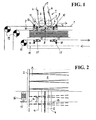
- Fig. 1 shows a schematic representation of an end view of a nonwoven layer in the same laying position.
- the nonwoven is executed in the example shown as Steilarmleger and shows him only the laying area at the lower end of the laying arm 1, which forms the laying member.
- the lower end of the laying arm 1 is movable back and forth across an endless circulating delivery conveyor belt 2 transversely to its direction of movement.
- the delivery conveyor belt 2 runs over a plurality of deflection and support rollers, which are not shown in FIG. 1 for reasons of clarity.
- rollers 3 forming a first pair of rollers are rotatably mounted, which are each surrounded by a feed belt 4, which are closely adjacent to one another in their sections running towards the lower end of the laying arm 1 and clamp a card web 5 between them in Fig. 1 as a thick line, partially dashed, is shown.
- rollers 6 of a second pair of rollers are in close proximity to the rollers 3 of the first pair of rollers.
- the rollers 6 are each wrapped by a cover strip 7, the lower strands extend over the delivery conveyor belt 2 and serve to cover the filed by the laying arm 1 on the delivery conveyor belt 2 pile layers.
- rollers 3 and 6 of each pair each have such a small distance to each other that the card web 5 is clamped between them.
- the gap between the rollers 6 of the second pair of rollers determines a denomination designated 8, at which the pile 5 is discharged to be deposited on the delivery conveyor belt 2.
- the two roller pairs 3 and 6 are mounted on a common laying carriage 9, which is movable on rails (not shown here) transversely to the longitudinal extent of the delivery conveyor belt 2 back and forth.
- the first displacement slide 11 are mounted in the laying carriage 9 and therefore moved together with the laying point 8 back and forth on the delivery conveyor belt 2. Every first sliding carriage 11 has a drive 12, with the aid of the distance of the relevant radiation transmitting device 10 is adjustable to the laying point 8.
- the radiation receiving devices 13 which are reciprocable in synchronism with the movement of the beam transmitting devices 10. This is illustrated in the drawing by a toothed belt 14, which runs around a drive gear 15 which is drivable by a motor 16 (see FIG. 2) in alternating directions of rotation.
- the radiation receiving devices 13 are attached to the toothed belt 14 respectively by means of a second sliding carriage 17 with associated drive means 18, so that their position along the toothed belt 14 in accordance with a displacement of the beam transmitting devices 10 can be adjusted.
- the laying carriage 9 is connected to a drive device which generates its movement over the delivery conveyor belt 2.
- the drive it sledge 9 can be done by means of two acting on a cover strip 7 drive rollers, which are driven at different peripheral speeds, as shown symbolically in the drawing by the black / white rauted guide rollers 19.
- the difference in the peripheral speeds of the driven deflection rollers 19 determines the speed of movement of the squeegee 9, while the absolute speed level of the driven guide rollers determines the speed at which the lower run of a cover strip 7 moves over the deposited pile layers.
- the masking tapes 7 have in each case at the deflecting them on the laying carriage 9 rollers 6 a rotational speed to produce at the gap between the rollers 6 of the second pair of rollers, a peripheral speed, which conveys the card web 5 from the gap between the rollers 6 and on the Abendertransportband 2 or the already stored thereon piles deposits.
- the drive of the cover strips 7 is independent of the drive of the feed belts 4 controllable. It is therefore possible to impart to the rollers 6 of the second pair of rollers a deviating from the rollers 3 of the first pair of rollers peripheral speed to stretch the card web 5 in the region between the two pairs of rollers 3 and 6 or to compress.
- the distance between the radiation transmitting devices 10 and the laying point 8 is preferably adjustable, for which purpose the first displacement slides 11 are provided. It is open This way it is possible to give the transmitting device 10 located in front in the direction of movement of the laying point 8 a greater distance to the laying point 8 than the transmitting device 10 located behind the laying point. In this way the time constants of the electrical switching devices receiving the signals from the receiving devices can be determined 13 received, take into account. Moves the landing spot 8 faster, the distance is to increase, it moves slower, it is to reduce. In practice, the movement of the laying point 8 is never uniform because it must be slowed down to zero when approaching the laying point 8 to the reversal points of the laying movement and then has to be accelerated again. It is understood that the radiation receiving means 13 must be moved accordingly, so that the radiation emitted by the radiation transmitting devices 10 beams can be recorded. Therefore, they are also along the toothed belt 14 relative to this adjustable.
- Fig. 2 is only the rounding of the sitter. It shows the result of the laying operation in the form of zigzag-shaped superimposed layers of the card web 5 after leaving the laying area on the supporting delivery conveyor belt 2. Furthermore, it can be seen that the radiation receiving devices 13 are in the area of the laying site, i. where the nonwoven web is produced, not outside of it, as in the prior art.
- the transmitting devices may be ⁇ -ray transmitters, X-ray transmitters, ultrasonic transmitters or RF transmitters, and the receiving devices are adapted to the physics of the transmitting devices, respectively. Alternatively, one can work with capacitive devices.
Landscapes
- Engineering & Computer Science (AREA)
- Textile Engineering (AREA)
- Preliminary Treatment Of Fibers (AREA)
- Nonwoven Fabrics (AREA)
Priority Applications (3)
| Application Number | Priority Date | Filing Date | Title |
|---|---|---|---|
| AT05008424T ATE368143T1 (de) | 2005-04-18 | 2005-04-18 | Verfahren zum steuern der florablage bei der erzeugung eines faservlieses und vorrichtung zum erzeugen eines faservlieses |
| EP05008424A EP1715093B1 (fr) | 2005-04-18 | 2005-04-18 | Procédé pour réguler le dépôt d'un voile lors de la formation d'une nappe non-tissée et installation s'y rapportant. |
| DE502005001103T DE502005001103D1 (de) | 2005-04-18 | 2005-04-18 | Verfahren zum Steuern der Florablage bei der Erzeugung eines Faservlieses und Vorrichtung zum Erzeugen eines Faservlieses |
Applications Claiming Priority (1)
| Application Number | Priority Date | Filing Date | Title |
|---|---|---|---|
| EP05008424A EP1715093B1 (fr) | 2005-04-18 | 2005-04-18 | Procédé pour réguler le dépôt d'un voile lors de la formation d'une nappe non-tissée et installation s'y rapportant. |
Publications (2)
| Publication Number | Publication Date |
|---|---|
| EP1715093A1 true EP1715093A1 (fr) | 2006-10-25 |
| EP1715093B1 EP1715093B1 (fr) | 2007-07-25 |
Family
ID=35640358
Family Applications (1)
| Application Number | Title | Priority Date | Filing Date |
|---|---|---|---|
| EP05008424A Expired - Lifetime EP1715093B1 (fr) | 2005-04-18 | 2005-04-18 | Procédé pour réguler le dépôt d'un voile lors de la formation d'une nappe non-tissée et installation s'y rapportant. |
Country Status (3)
| Country | Link |
|---|---|
| EP (1) | EP1715093B1 (fr) |
| AT (1) | ATE368143T1 (fr) |
| DE (1) | DE502005001103D1 (fr) |
Cited By (1)
| Publication number | Priority date | Publication date | Assignee | Title |
|---|---|---|---|---|
| EP2014813A1 (fr) | 2007-07-09 | 2009-01-14 | Oskar Dilo Maschinenfabrik KG | Procédé de fabrication d'un non tissée consolidé |
Citations (4)
| Publication number | Priority date | Publication date | Assignee | Title |
|---|---|---|---|---|
| US4107822A (en) * | 1977-06-08 | 1978-08-22 | Roger Alan Brown | Process for making a batt of modified basis weight profile and lengthwise uniformity |
| EP0315930A2 (fr) * | 1987-11-10 | 1989-05-17 | AUTEFA Holding GmbH | Plieuse pour voile |
| FR2794475A1 (fr) * | 1999-06-01 | 2000-12-08 | Asselin | Procede pour reguler le profil d'une nappe non-tissee et installation de production s'y rapportant |
| US6195844B1 (en) * | 1997-11-07 | 2001-03-06 | Asselin | Method and devices for producing a textile fleece |
-
2005
- 2005-04-18 AT AT05008424T patent/ATE368143T1/de active
- 2005-04-18 EP EP05008424A patent/EP1715093B1/fr not_active Expired - Lifetime
- 2005-04-18 DE DE502005001103T patent/DE502005001103D1/de not_active Expired - Lifetime
Patent Citations (5)
| Publication number | Priority date | Publication date | Assignee | Title |
|---|---|---|---|---|
| US4107822A (en) * | 1977-06-08 | 1978-08-22 | Roger Alan Brown | Process for making a batt of modified basis weight profile and lengthwise uniformity |
| EP0315930A2 (fr) * | 1987-11-10 | 1989-05-17 | AUTEFA Holding GmbH | Plieuse pour voile |
| US6195844B1 (en) * | 1997-11-07 | 2001-03-06 | Asselin | Method and devices for producing a textile fleece |
| FR2794475A1 (fr) * | 1999-06-01 | 2000-12-08 | Asselin | Procede pour reguler le profil d'une nappe non-tissee et installation de production s'y rapportant |
| US6434795B1 (en) * | 1999-06-01 | 2002-08-20 | Asselin | Method for controlling the profile of a non-woven lap and related production installation |
Cited By (2)
| Publication number | Priority date | Publication date | Assignee | Title |
|---|---|---|---|---|
| EP2014813A1 (fr) | 2007-07-09 | 2009-01-14 | Oskar Dilo Maschinenfabrik KG | Procédé de fabrication d'un non tissée consolidé |
| US7581294B2 (en) | 2007-07-09 | 2009-09-01 | Oskar Dilo Maschinenfabrik Kg | Method of manufacturing a nonwoven |
Also Published As
| Publication number | Publication date |
|---|---|
| ATE368143T1 (de) | 2007-08-15 |
| EP1715093B1 (fr) | 2007-07-25 |
| DE502005001103D1 (de) | 2007-09-06 |
Similar Documents
| Publication | Publication Date | Title |
|---|---|---|
| EP2695976B1 (fr) | Dispositif pour délivrer des fibres divisées ou des bourres de fibres sur un dispositif de transport | |
| EP2014813B1 (fr) | Procédé de fabrication d'un non tissée consolidé | |
| DE60038187T2 (de) | Verfahren und anlage zum regeln des profils eines faservliesverbundes | |
| EP1285982B1 (fr) | Procédé et dispositif pour produire un voile de fibres | |
| EP2881509B1 (fr) | Empileur tourne-piles | |
| EP1454133A2 (fr) | Utilisation de micro-ondes dans l'industrie de la filature | |
| EP0123969B1 (fr) | Procédé pour la fabrication d'un feutre tubulaire sans fin, et appareil pour exécuter ce procédé | |
| EP1643022B1 (fr) | Procédé pour profiler un non-tissé et dispositif de formation de profils | |
| EP2673410A1 (fr) | Procédé et dispositif de consolidation d'une nappe de tissu amenée en continu | |
| EP2545213B1 (fr) | Procédé et dispositif servant à mesurer le poids d'un flux sans fin d'un matériau fibreux en bande | |
| EP2660375A2 (fr) | Procédé et dispositif de réglage de l'orientation des fibres dans des installations de carde | |
| EP3110997B1 (fr) | Dispositif de cardage et procédé de cardage | |
| EP1493854B1 (fr) | Procédé et installation pour la formation de non-tissés | |
| DE29909016U1 (de) | Vliesanlage | |
| EP1715093B1 (fr) | Procédé pour réguler le dépôt d'un voile lors de la formation d'une nappe non-tissée et installation s'y rapportant. | |
| EP3066239A2 (fr) | Dispositif de pose de non-tissé et procédé de pose de non-tissé | |
| DE3843180C2 (fr) | ||
| EP2169095B1 (fr) | Installation de dépose régulière d'un voile de fibres | |
| DE20113467U1 (de) | Streckwerk und Vorrichtung zum Herstellen eines Faservlieses | |
| EP2843096B1 (fr) | Procédé et dispositif destinés à produire une structure | |
| WO1993024692A1 (fr) | Procede de fabrication de non-tisses, ainsi que plisseur transversal | |
| DD296156A5 (de) | Verfahren zum erfassen und ausgleichen von legefehlern beim herstellen einer bahn eines mehrlagigen vlieses und legemaschine zu seiner anwendung | |
| EP2635729B1 (fr) | Dispositif de depot de bande de non-tisse et procede pour former un non-tisse |
Legal Events
| Date | Code | Title | Description |
|---|---|---|---|
| PUAI | Public reference made under article 153(3) epc to a published international application that has entered the european phase |
Free format text: ORIGINAL CODE: 0009012 |
|
| 17P | Request for examination filed |
Effective date: 20060330 |
|
| AK | Designated contracting states |
Kind code of ref document: A1 Designated state(s): AT BE BG CH CY CZ DE DK EE ES FI FR GB GR HU IE IS IT LI LT LU MC NL PL PT RO SE SI SK TR |
|
| AX | Request for extension of the european patent |
Extension state: AL BA HR LV MK YU |
|
| GRAP | Despatch of communication of intention to grant a patent |
Free format text: ORIGINAL CODE: EPIDOSNIGR1 |
|
| GRAS | Grant fee paid |
Free format text: ORIGINAL CODE: EPIDOSNIGR3 |
|
| GRAA | (expected) grant |
Free format text: ORIGINAL CODE: 0009210 |
|
| AKX | Designation fees paid |
Designated state(s): AT DE FR IT |
|
| AK | Designated contracting states |
Kind code of ref document: B1 Designated state(s): AT DE FR IT |
|
| REF | Corresponds to: |
Ref document number: 502005001103 Country of ref document: DE Date of ref document: 20070906 Kind code of ref document: P |
|
| ET | Fr: translation filed | ||
| PLBE | No opposition filed within time limit |
Free format text: ORIGINAL CODE: 0009261 |
|
| STAA | Information on the status of an ep patent application or granted ep patent |
Free format text: STATUS: NO OPPOSITION FILED WITHIN TIME LIMIT |
|
| 26N | No opposition filed |
Effective date: 20080428 |
|
| REG | Reference to a national code |
Ref country code: FR Ref legal event code: PLFP Year of fee payment: 12 |
|
| REG | Reference to a national code |
Ref country code: FR Ref legal event code: PLFP Year of fee payment: 13 |
|
| REG | Reference to a national code |
Ref country code: FR Ref legal event code: PLFP Year of fee payment: 14 |
|
| PGFP | Annual fee paid to national office [announced via postgrant information from national office to epo] |
Ref country code: DE Payment date: 20190430 Year of fee payment: 15 Ref country code: IT Payment date: 20190430 Year of fee payment: 15 |
|
| PGFP | Annual fee paid to national office [announced via postgrant information from national office to epo] |
Ref country code: FR Payment date: 20190423 Year of fee payment: 15 |
|
| PGFP | Annual fee paid to national office [announced via postgrant information from national office to epo] |
Ref country code: AT Payment date: 20190424 Year of fee payment: 15 |
|
| REG | Reference to a national code |
Ref country code: DE Ref legal event code: R119 Ref document number: 502005001103 Country of ref document: DE |
|
| REG | Reference to a national code |
Ref country code: AT Ref legal event code: MM01 Ref document number: 368143 Country of ref document: AT Kind code of ref document: T Effective date: 20200418 |
|
| PG25 | Lapsed in a contracting state [announced via postgrant information from national office to epo] |
Ref country code: FR Free format text: LAPSE BECAUSE OF NON-PAYMENT OF DUE FEES Effective date: 20200430 Ref country code: AT Free format text: LAPSE BECAUSE OF NON-PAYMENT OF DUE FEES Effective date: 20200418 Ref country code: DE Free format text: LAPSE BECAUSE OF NON-PAYMENT OF DUE FEES Effective date: 20201103 |
|
| PG25 | Lapsed in a contracting state [announced via postgrant information from national office to epo] |
Ref country code: IT Free format text: LAPSE BECAUSE OF NON-PAYMENT OF DUE FEES Effective date: 20200418 |