EP1715094A1 - Dispositif de chauffage et machine de traitement de fil - Google Patents
Dispositif de chauffage et machine de traitement de fil Download PDFInfo
- Publication number
- EP1715094A1 EP1715094A1 EP05008595A EP05008595A EP1715094A1 EP 1715094 A1 EP1715094 A1 EP 1715094A1 EP 05008595 A EP05008595 A EP 05008595A EP 05008595 A EP05008595 A EP 05008595A EP 1715094 A1 EP1715094 A1 EP 1715094A1
- Authority
- EP
- European Patent Office
- Prior art keywords
- yarn
- heater
- winding
- heating
- feedthrough
- Prior art date
- Legal status (The legal status is an assumption and is not a legal conclusion. Google has not performed a legal analysis and makes no representation as to the accuracy of the status listed.)
- Withdrawn
Links
- 238000010438 heat treatment Methods 0.000 claims abstract description 48
- 238000004804 winding Methods 0.000 claims abstract description 47
- 230000000694 effects Effects 0.000 description 7
- 238000001816 cooling Methods 0.000 description 5
- 239000012080 ambient air Substances 0.000 description 2
- MHCVCKDNQYMGEX-UHFFFAOYSA-N 1,1'-biphenyl;phenoxybenzene Chemical group C1=CC=CC=C1C1=CC=CC=C1.C=1C=CC=CC=1OC1=CC=CC=C1 MHCVCKDNQYMGEX-UHFFFAOYSA-N 0.000 description 1
- 230000001419 dependent effect Effects 0.000 description 1
- 230000001151 other effect Effects 0.000 description 1
- 239000004753 textile Substances 0.000 description 1
Images
Classifications
-
- D—TEXTILES; PAPER
- D02—YARNS; MECHANICAL FINISHING OF YARNS OR ROPES; WARPING OR BEAMING
- D02J—FINISHING OR DRESSING OF FILAMENTS, YARNS, THREADS, CORDS, ROPES OR THE LIKE
- D02J13/00—Heating or cooling the yarn, thread, cord, rope, or the like, not specific to any one of the processes provided for in this subclass
- D02J13/003—Heating or cooling the yarn, thread, cord, rope, or the like, not specific to any one of the processes provided for in this subclass by contact with at least one stationary surface, e.g. a plate
Definitions
- the invention relates to a device for heat treatment of a synthetic yarn (yarn heater), in particular a contact heater, with at least one arranged on a Garn gagation wall, and heating means, which are adapted to heat the Schuwanditch.
- yarn heaters are used in particular in false-twist texturing machines.
- Texturing especially false-twist texturing, of filament yarns, especially multifilament yarns
- the purpose of texturing is to produce from a plastic-like, flat and smooth multifilament yarn a curled and structured yarn which, due to its voluminous and bulky structure (Bausch), has a textile character.
- the multifilament yarn is generally unwound from a bobbin, passed through a first delivery mechanism, then heated in a yarn heater (primary heater), cooled on a cooling rail, passed through a swirl transmitter and a second delivery mechanism arranged behind it, a so-called trigger delivery unit, and then to a Garnspule to be wound up.
- the swirl transmitter serves to temporarily turn up the multifilament yarn in one operation, i.
- This temporary twisting (twisted state) is called false-twisted wire (FD).
- the twisting forms a spinlock which extends back into the yarn heater (swirl zone), thereby allowing the twisted state of the filament yarns in front of the swirl donor by heating the yarn to a temperature at which the yarn is plastically deformable and thereupon the following cooling is thermally fixed. Behind the twist donor, the twist is then resolved again. Due to the thermal fixation in the twisted state, the yarn has the desired crimped structure.
- the yarn heater is usually mounted in a false-twist texturing machine with its yarn feedthrough perpendicular to the horizontal.
- Garnheizer electric heaters ie Garnheizer whose heating means have a heating wire, which is acted upon by an electrical voltage
- Diphylheizer used.
- a yarn passing through the yarn is heated by contact with a gas or vapor heating medium.
- An example of such a yarn heater is eg in the DE 3435427 A1 disclosed.
- electrical Yarn heaters have the disadvantage over Diphylheizern that a temperature profile does not run evenly within the Garnd trimer. Diphyl heaters, however, always have a temperature profile with a rectangular profile profile within the yarn feedthrough.
- the temperature profile falls during operation of the yarn heater to the ends of the heater, ie to end portions of the Garn trim arrangement, down from. This is a consequence of the increased heat loss at the openings of the yarn feedthrough arranged at the ends of the yarn feedthrough. Due to the vertical course of the Garnd to arrangement further occurs a chimney effect, which is superimposed on the falling of the temperature profile in the end regions. This chimney effect results from the fact that cold ambient air is sucked in at the lower opening of the yarn feedthrough, which cools a part of the yarn feedthrough adjacent to the lower opening or of the adjacent heating wall. The uneven course of the temperature profile can lead to disturbances in false-twist texturing. In particular, a predetermined heating of the yarn feedthrough passing yarn is difficult to achieve.
- the invention has for its object to provide an electrically operated Garnheizer and a yarn processing machine, which avoid the disadvantages of the prior art, in particular in which a desired temperature profile is maintained within the Garnd gagation during operation of the yarn heater.
- At least one heating wall is arranged on a yarn feedthrough, and heating means are provided which are set up for heating the heating walls.
- the heating means on Bankdrahtwicklonne along the Garn trim entry wherein the Schudrahtwicklonne have winding sections, each with a winding density and the winding densities to achieve a present during operation of the yarn heater within the Garn trim entry temperature profile at least partially vary.
- the yarn heater according to the invention is preferably designed as a contact heater, in particular for use in a false-twist texturing machine.
- a contact heater is constructed such that there is a direct contact of the heating wall with a yarn to be heated during its operation.
- yarn guides within the Garn gage which enforce a distance of the yarn to the heating wall.
- the winding densities are varied in such a way that the temperature profile has a rectangular profile profile.
- a heating of the yarn can be optimally adjusted.
- a winding density of a winding section in an end region of the yarn feedthrough is increased compared to at least one winding density in a winding section of a central region of the yarn feedthrough.
- the winding density in at least one winding section can proceed continuously, preferably linearly, along the yarn feedthrough. Due to the continuous course of the winding density occurring within the Garn just tip extraction is compensated by a chimney effect with vertical mounting of the yarn heater according to the invention.
- a yarn processing machine in particular false twist texturing machine, has at least one yarn heater according to the invention. If the yarn heater is mounted on the yarn processing machine in such a way that the yarn feedthrough is aligned at least with one component perpendicular to the horizontal, the winding density is advantageously varied continuously, at least in one winding section, in order to avoid the described chimney effect.
- the yarn feedthrough is aligned with a component perpendicular to the horizontal when it is not parallel to the horizontal, whereby one end portion of the yarn feedthrough is located above the other end portion of the yarn feedthrough.
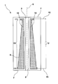
- an inventive designed as a contact heater Garnheizer 1 is shown.
- the Garnheizer 1 has a Garn take arrangement 3, which at a Heating wall 5 is positioned.
- a yarn 6 whose yarn course in the figure is congruent with the rotational symmetry axis of the Schudrahtwicklept passes through the Garn trim operation 3.
- the illustration of the figure shows a sectional plane through the Garnheizer 1 along the Garn trim arrangement 3.
- the Garnheizer 1 is corresponding to an insert in a false-wire texturing with the Garn trim enclosure 3 shown perpendicular to the horizontal, wherein the horizontal along an upper and lower edge 7 of the heater 1 extends.
- the heating wall 5 is formed in the illustrated Garnheizer 1 of the inner surface of the Garn press operation 3 forming cylinder.
- Heating means 9 of the yarn heater 1 are arranged on the heating wall 5 that they serve to heat the heating wall 5.
- the heating means 9 have along the Garn prepare for construction.
- Sections of these Bankdrahtwicklonne 10 are shown in the figure as points within the heating means 9.
- the illustrated Garnheizer 1 the Gardrahtwicklened 10 are arranged around the yarn feedthrough 3 forming cylinder around, ie, a heating wire is wound around the cylinder.
- These Schudrahtwicklonne 10 have different winding sections 11,12,13, each with a winding density.
- the winding density is determined by the number of Bankdrahtwicklitch 10 per unit length along the Garn trim entry 3.
- the winding densities vary to achieve a temperature profile.
- the heating means 9 are electrically operated.
- an electrical voltage U is applied to the heating wire windings 10 via electrical connections 15.
- the winding densities are varied in such a way that the temperature profile has a rectangular profile profile when installed vertically in a false-twist texturing machine.
- the winding densities of the winding sections 11, 13 in end regions of the yarn feedthrough 3 are increased relative to the winding density in the winding section 12 in a central region of the yarn feedthrough 3.
- heat losses at the end portions of the Garn trim arrangement 3 are compensated. Due to the vertical mounting of the yarn heater 1, an end region is arranged above the other end region.
- the winding density in the central region is linearly increased along the yarn feedthrough 3 from the upper end region to the lower end region. This has the consequence that an uneven heating of the heating wall 5 is compensated by a chimney effect to achieve the rectangular profile profile in the Garn trim arrangement 3. In such a chimney effect, cold ambient air is drawn in at the lower end region, which leads to cooling of the heating wall 5 in this area. To compensate for this cooling an increasing number of Bankdrahtwicklitch 10 is provided in the central region running down.
- the illustrated variation of the winding densities of the heating wire leads to a distribution of the heating power within the yarn duct 3 such that the temperature profile during the operation of the yarn heater 1 is almost rectangular, i. the heat output, running at the ends and over the length of the Garn trim arrangement 3 to the lower end region, is increased to compensate for heat losses and the chimney effect.
- a yarn heater 1 is proposed, in particular for use in a false-twist texturing machine, with at least one heating wall 5 arranged on a yarn duct 3, and heating means 9 adapted for heating the heating walls 5, the heating means 9 having heating-wire windings 10 along the yarn duct 3 the Bankdrahtwicklitch 10 winding sections 11,12,13 each having a winding density and the winding densities to achieve a temperature profile in an operation of the yarn heater at least partially vary.
Landscapes
- Engineering & Computer Science (AREA)
- Textile Engineering (AREA)
- Yarns And Mechanical Finishing Of Yarns Or Ropes (AREA)
Priority Applications (1)
| Application Number | Priority Date | Filing Date | Title |
|---|---|---|---|
| EP05008595A EP1715094A1 (fr) | 2005-04-20 | 2005-04-20 | Dispositif de chauffage et machine de traitement de fil |
Applications Claiming Priority (1)
| Application Number | Priority Date | Filing Date | Title |
|---|---|---|---|
| EP05008595A EP1715094A1 (fr) | 2005-04-20 | 2005-04-20 | Dispositif de chauffage et machine de traitement de fil |
Publications (1)
| Publication Number | Publication Date |
|---|---|
| EP1715094A1 true EP1715094A1 (fr) | 2006-10-25 |
Family
ID=35432099
Family Applications (1)
| Application Number | Title | Priority Date | Filing Date |
|---|---|---|---|
| EP05008595A Withdrawn EP1715094A1 (fr) | 2005-04-20 | 2005-04-20 | Dispositif de chauffage et machine de traitement de fil |
Country Status (1)
| Country | Link |
|---|---|
| EP (1) | EP1715094A1 (fr) |
Citations (2)
| Publication number | Priority date | Publication date | Assignee | Title |
|---|---|---|---|---|
| DE3435427A1 (de) * | 1983-10-11 | 1985-04-25 | Barmag Barmer Maschinenfabrik Ag, 5630 Remscheid | Vorrichtung an texturiermaschinen zur gleichmaessigen aufheizung des durchlaufenden fadens |
| US4880961A (en) * | 1988-03-02 | 1989-11-14 | E. I. Du Pont De Nemours And Company | Apparatus for heating yarn |
-
2005
- 2005-04-20 EP EP05008595A patent/EP1715094A1/fr not_active Withdrawn
Patent Citations (2)
| Publication number | Priority date | Publication date | Assignee | Title |
|---|---|---|---|---|
| DE3435427A1 (de) * | 1983-10-11 | 1985-04-25 | Barmag Barmer Maschinenfabrik Ag, 5630 Remscheid | Vorrichtung an texturiermaschinen zur gleichmaessigen aufheizung des durchlaufenden fadens |
| US4880961A (en) * | 1988-03-02 | 1989-11-14 | E. I. Du Pont De Nemours And Company | Apparatus for heating yarn |
Similar Documents
| Publication | Publication Date | Title |
|---|---|---|
| WO2004074155A1 (fr) | Dispositif pour fabriquer et enrouler des fils synthetiques | |
| DE68915572T2 (de) | Falschzwirnmaschine. | |
| DE69405628T2 (de) | Kühlvorrichtung von einer Falschzwirntexturiermaschine | |
| DE3018365C2 (de) | Falschdralltexturiermaschine | |
| EP2527502B1 (fr) | Dispositif d'enlèvement et d'étirage d'un fil synthétique | |
| DE1660352B1 (de) | Kuehlvorrichtung in einer Einrichtung zum Texturieren von mindestens teilweise aus thermoplastischem Material bestehenden Garnen | |
| EP2347045B1 (fr) | Dispositif de chauffage | |
| EP2994560B1 (fr) | Procédé et dispositif de traitement de faisceaux de fibres de carbone | |
| EP0718424B1 (fr) | Machine d'étirage-texturation pour fils synthétiques | |
| EP1114212B1 (fr) | Machine de texturation | |
| EP1523592A1 (fr) | Machine de texturation par fausse torsion | |
| EP2627808B1 (fr) | Dispositif pour le traitement thermique de plusiers fils | |
| DE4415229A1 (de) | Verfahren zum kontinuierlichen Wärmebehandeln von in Schlaufen abgelegtem Garn | |
| EP0406673B1 (fr) | Machine de frisage par fausse-torsion pour fil synthétique | |
| EP2049714A2 (fr) | Machine à texturer | |
| DE2248808A1 (de) | Vorrichtung zur falschdrall-texturierung und nachfixierung von aus thermoplastischem synthetischem material bestehenden garnen in kontinuierlicher arbeitsweise | |
| EP0932712A1 (fr) | Machine de texturation de faux fils tordus et procede de production d'un fil texture | |
| EP1409777A1 (fr) | Machine de texturation a fausse torsion | |
| EP1598457A1 (fr) | Machine de texturation par fausse torsion et/ou machine de guipage par jet d'air | |
| DE10258262A1 (de) | Heizvorrichtung und Verfahren zum Erwärmen eines Fadens | |
| EP1584717A1 (fr) | Machine de traitement de fil | |
| EP0193891A2 (fr) | Dispositif de chauffage pour machine à friser | |
| DE1903365A1 (de) | Falschdrallkraeuselmaschine | |
| EP1614781A1 (fr) | machine de fausse torsion | |
| DE10354457A1 (de) | Verfahren und Vorrichtung zum Strecktexturieren eines synthetischen Fadens |
Legal Events
| Date | Code | Title | Description |
|---|---|---|---|
| PUAI | Public reference made under article 153(3) epc to a published international application that has entered the european phase |
Free format text: ORIGINAL CODE: 0009012 |
|
| AK | Designated contracting states |
Kind code of ref document: A1 Designated state(s): AT BE BG CH CY CZ DE DK EE ES FI FR GB GR HU IE IS IT LI LT LU MC NL PL PT RO SE SI SK TR |
|
| AX | Request for extension of the european patent |
Extension state: AL BA HR LV MK YU |
|
| AKX | Designation fees paid | ||
| STAA | Information on the status of an ep patent application or granted ep patent |
Free format text: STATUS: THE APPLICATION IS DEEMED TO BE WITHDRAWN |
|
| 18D | Application deemed to be withdrawn |
Effective date: 20070426 |
|
| REG | Reference to a national code |
Ref country code: DE Ref legal event code: 8566 |