EP1715200A2 - Articulation à rotule - Google Patents
Articulation à rotule Download PDFInfo
- Publication number
- EP1715200A2 EP1715200A2 EP06002018A EP06002018A EP1715200A2 EP 1715200 A2 EP1715200 A2 EP 1715200A2 EP 06002018 A EP06002018 A EP 06002018A EP 06002018 A EP06002018 A EP 06002018A EP 1715200 A2 EP1715200 A2 EP 1715200A2
- Authority
- EP
- European Patent Office
- Prior art keywords
- ball
- vehicle component
- joint
- facing
- ball joint
- Prior art date
- Legal status (The legal status is an assumption and is not a legal conclusion. Google has not performed a legal analysis and makes no representation as to the accuracy of the status listed.)
- Granted
Links
Images

Classifications
-
- F—MECHANICAL ENGINEERING; LIGHTING; HEATING; WEAPONS; BLASTING
- F16—ENGINEERING ELEMENTS AND UNITS; GENERAL MEASURES FOR PRODUCING AND MAINTAINING EFFECTIVE FUNCTIONING OF MACHINES OR INSTALLATIONS; THERMAL INSULATION IN GENERAL
- F16C—SHAFTS; FLEXIBLE SHAFTS; ELEMENTS OR CRANKSHAFT MECHANISMS; ROTARY BODIES OTHER THAN GEARING ELEMENTS; BEARINGS
- F16C11/00—Pivots; Pivotal connections
- F16C11/04—Pivotal connections
- F16C11/06—Ball-joints; Other joints having more than one degree of angular freedom, i.e. universal joints
- F16C11/0604—Construction of the male part
-
- F—MECHANICAL ENGINEERING; LIGHTING; HEATING; WEAPONS; BLASTING
- F16—ENGINEERING ELEMENTS AND UNITS; GENERAL MEASURES FOR PRODUCING AND MAINTAINING EFFECTIVE FUNCTIONING OF MACHINES OR INSTALLATIONS; THERMAL INSULATION IN GENERAL
- F16C—SHAFTS; FLEXIBLE SHAFTS; ELEMENTS OR CRANKSHAFT MECHANISMS; ROTARY BODIES OTHER THAN GEARING ELEMENTS; BEARINGS
- F16C11/00—Pivots; Pivotal connections
- F16C11/04—Pivotal connections
- F16C11/06—Ball-joints; Other joints having more than one degree of angular freedom, i.e. universal joints
- F16C11/0695—Mounting of ball-joints, e.g. fixing them to a connecting rod
-
- B—PERFORMING OPERATIONS; TRANSPORTING
- B60—VEHICLES IN GENERAL
- B60G—VEHICLE SUSPENSION ARRANGEMENTS
- B60G2204/00—Indexing codes related to suspensions per se or to auxiliary parts
- B60G2204/40—Auxiliary suspension parts; Adjustment of suspensions
- B60G2204/416—Ball or spherical joints
-
- F—MECHANICAL ENGINEERING; LIGHTING; HEATING; WEAPONS; BLASTING
- F16—ENGINEERING ELEMENTS AND UNITS; GENERAL MEASURES FOR PRODUCING AND MAINTAINING EFFECTIVE FUNCTIONING OF MACHINES OR INSTALLATIONS; THERMAL INSULATION IN GENERAL
- F16C—SHAFTS; FLEXIBLE SHAFTS; ELEMENTS OR CRANKSHAFT MECHANISMS; ROTARY BODIES OTHER THAN GEARING ELEMENTS; BEARINGS
- F16C2326/00—Articles relating to transporting
- F16C2326/01—Parts of vehicles in general
Definitions
- the invention relates to a ball joint connection according to the type specified in the preamble of claim 1.
- a generic ball joint connection is in the DE 199 50 281 B4 described. It has a ball stud with a ball joint, wherein the cylindrical shank of the ball stud extends from one side of a component through a through hole disposed therein to the other side and is axially fixed therein, wherein in the wall of the through hole, a continuous axially parallel groove is arranged.
- a further ball joint connection in which a ball joint having a ball pin is guided in a through-opening having a component.
- the guided in the component ball pin has a conical portion and an end portion of the pin is provided with a thread, via which the ball pin is detachably connectable to the component.
- the thread of the pin protrudes into the passage opening and it has in its foot region an undercut formed by an annular recess.
- the invention has the object of developing a ball joint connection according to the type specified in the preamble of claim 1 while avoiding the disadvantages mentioned in such a way that the risk of cracking and premature failure of the component is reduced.
- the invention is based on the finding that by a targeted reduction of the stresses caused by a radial force acting on the joint ball in the edge region of the joint ball facing the joint ball Through hole / opening of the component, the risk of cracking in this area is reduced and thus a longer life of the component is ensured.
- the ball joint connection comprises a ball stud with a ball joint, wherein the ball stud is guided via a bush in a through hole of a vehicle component and is detachably connected to the vehicle component.
- the bushing has a bushing flange in an end region facing the ball joint, wherein the bushing flange rests on a contact surface of the vehicle component.
- a gap extending in the axial direction is arranged between the end region of the vehicle component facing the joint ball and the end region of the bush facing the joint ball.
- the bushing flange is pot-shaped, having a bottom and wall region, and only the wall region of the pot-shaped bushing flange rests on the contact surface of the vehicle component that corresponds to it.
- the wall region of the bushing flange and the contact surface of the vehicle component are formed conically.
- the conical configuration of these surfaces proves to be advantageous because these production technology are easy to manufacture.
- the wall portion of the bushing flange and the contact surface of the vehicle component are formed dome-shaped.
- the dome-shaped design proves to be advantageous, as a result, a larger contact area between the wall portion of the Buchsenflansches and the vehicle component is available, causing a further reduction of the local stress level in the joint ball facing edge region of the through hole of the vehicle component.
- a gap extending in the axial direction is also arranged between the end region of the vehicle component facing the joint ball and the end region of the bush facing the joint ball.
- an additional voltage displacement is due in a particularly advantageous manner, since, as already stated, the voltages occurring are displaced by the edge of the through hole of the vehicle component facing the ball joint in the interior of the vehicle component through the gap.
- the gap arranged between the end of the vehicle component facing the joint ball and the end region of the bush facing the joint ball is formed by a radially circumferential groove.
- the groove is preferably introduced into the end region of the vehicle component facing the joint ball and / or into the end region of the bush facing the joint ball.
- the gap in the axial direction considered a length of about 1/4 to 1/3 of the diameter of the through hole and in the radial direction considers a width of about 0.1 mm to 2 mm, but in particular 1 mm.
- the ball stud has a conical or cylindrical outer lateral surface and the bush has a cylindrical or conical inner lateral surface corresponding thereto.
- a screw connection is arranged in a region of the ball pin opposite the joint ball, via which the ball pin is detachably connected to the vehicle component.
- the bushing is preferably pressed or screwed into the vehicle component.
- the socket and the vehicle component are made of different components, in particular the bush made of steel and the component made of aluminum.
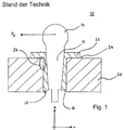
- ball joint connection essentially comprises a ball pin 12 with a ball joint 14, via a socket 16 in a through hole 18 of a Vehicle component 20 is guided and releasably connected to the vehicle component 20.
- the bushing 16 has a bushing flange 22 and is arranged in the through hole 18 such that the bushing flange 22 of the bush rests on an associated contact surface 24 of the vehicle component 20.
- the ball-and-socket joint 10 known from the prior art proves to be disadvantageous, since a radial force F R acting on the joint ball 14 leads to a stress concentration in the edge region of the through-bore 18 facing the joint ball 14, symbolized here by reference number 26. This stress concentration in the region 26 can lead to cracking and thus premature failure of the vehicle component 20.
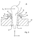
- a gap 27 extending in the axial direction a is arranged between the end region of the vehicle component 20 facing the joint ball 14 and the end region of the bush 16 facing the joint ball 14.
- the inventive arrangement of the gap 27 ensures that the stresses caused by radial forces F R are no longer concentrated on the region 26 of the vehicle component 20, but are displaced into a region 29 in the interior of the vehicle component 20.
- the gap 29 is formed by a, only introduced into the bush 16, radially encircling groove 31.
- the groove 31 can also be formed by a groove 31 which is arranged only in the vehicle component 20 or by two oppositely disposed respectively in the bushing 16 and the vehicle component 20.
- the bushing flange 22 is pot-shaped, ie the bushing flange 22 comprises a bottom region 28 and a wall region 30 and only the wall region 30 of the cup-shaped bushing flange 22 lies on the correspondingly formed contact surface 24 of the vehicle component 20 on, while between the end face of the vehicle component 20 and the bottom portion 28 of the cup-shaped bushing flange 22, a gap 32 remains.
- the embodiment according to the invention of the bushing flange 22 and the associated contact surface 24 ensures that the stresses caused by radial forces F R are no longer concentrated exclusively on the region 26 of the vehicle component 20 but are additionally distributed over a further region 34 of the vehicle component 20.
- the resulting stress distribution thus reduces the local stresses in the region 26 and thus prevents crack formation in this region, so that a longer service life of the vehicle component 20 is ensured.
- the wall portion 30 of the cup-shaped bushing flange 22 and the corresponding thereto formed contact surface 24 of the vehicle component 20 are formed cone-shaped.
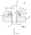
- FIG. 4 A further embodiment of the ball joint connection 10 according to the invention is shown in FIG. 4.
- the pot-shaped bushing flange 22 is designed differently in the case of the ball joint connection 10 shown in FIG. 3.
- the wall portion 30 of the Buchsenflansches 22 and the corresponding thereto formed contact surface 24 of the vehicle component 20 are formed dome-shaped.
- bushing flange 22 and contact surface 24 of the vehicle component 20 ensures that the bottom portion 28 of the Buchsenflansches 22 does not rest on the end face of the contact surface 24 of the vehicle component 20, but are positively connected to each other only via the Kalotten vom.
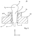
- FIG. 5 A further embodiment of the ball and socket joint 10 according to the invention is shown in FIG. 5.
- a gap 27 which has already been described above and which extends in the axial direction a is arranged ,
- the gap 38 causes an additional stress displacement of the stresses caused by the radial force F R in the region 29 in the interior of the vehicle component 20. This ensures a uniform distribution of stress over the entire vehicle component 20, which increases the risk of cracking in the vehicle component 20 additionally reduces and thus contributes to an increase in the service life of the vehicle component 20.
- the gap 27 has a length of about 1/4 to 1/3 of the diameter of the through hole 18 while viewed in the radial direction r, the gap 27 has a thickness of preferably 1mm.
- the illustrated ball pin 12 has a conical outer surface and the bush 16 has a conical inner surface which corresponds to it.
- the outer circumferential surface of the ball pin 12 and the correspondingly formed inner circumferential surface of the sleeve 16 may also be cylindrical.
- the bushing 16 is made of steel and the vehicle component 20 is made of aluminum, and the bush 16 guided in the through hole 18 of the vehicle component 20 is pressed into the vehicle component 20.
- the socket 16 may also be screwed into the vehicle component 20.
- the releasable connection of the ball pin 12 with the vehicle component 20 is in the ball joint connection 10 shown in FIGS. 2 to 5 according to the invention realized in each case by a, not shown here for clarity, screw that in an opposing ball 14 opposite portion of the ball pin 12th is arranged.
- the invention is characterized in that the local stress peaks in the region of the joint ball 14 facing edge region of the vehicle component 20 are degraded by targeted structural measures, whereby the risk of cracking minimized and thus a longer life of the vehicle component 20 is ensured.
Landscapes
- Engineering & Computer Science (AREA)
- General Engineering & Computer Science (AREA)
- Mechanical Engineering (AREA)
- Pivots And Pivotal Connections (AREA)
Applications Claiming Priority (2)
| Application Number | Priority Date | Filing Date | Title |
|---|---|---|---|
| DE102005018153 | 2005-04-20 | ||
| DE102005039402A DE102005039402B3 (de) | 2005-04-20 | 2005-08-20 | Kugelgelenkverbindung |
Publications (3)
| Publication Number | Publication Date |
|---|---|
| EP1715200A2 true EP1715200A2 (fr) | 2006-10-25 |
| EP1715200A3 EP1715200A3 (fr) | 2008-01-23 |
| EP1715200B1 EP1715200B1 (fr) | 2011-05-04 |
Family
ID=36729338
Family Applications (1)
| Application Number | Title | Priority Date | Filing Date |
|---|---|---|---|
| EP06002018A Expired - Lifetime EP1715200B1 (fr) | 2005-04-20 | 2006-02-01 | Articulation à rotule |
Country Status (2)
| Country | Link |
|---|---|
| EP (1) | EP1715200B1 (fr) |
| DE (2) | DE102005039402B3 (fr) |
Cited By (1)
| Publication number | Priority date | Publication date | Assignee | Title |
|---|---|---|---|---|
| CN113428221A (zh) * | 2021-07-09 | 2021-09-24 | 重庆长安汽车股份有限公司 | 一种汽车转向拉杆柔性连接结构 |
Families Citing this family (3)
| Publication number | Priority date | Publication date | Assignee | Title |
|---|---|---|---|---|
| DE102008061511A1 (de) | 2008-12-10 | 2010-06-17 | Daimler Ag | Kugelgelenkanordnung |
| DE102010023470A1 (de) | 2010-06-11 | 2011-12-15 | Dr. Ing. H.C. F. Porsche Aktiengesellschaft | Tragstruktur für einen Gelenkzapfen |
| DE102011001498A1 (de) | 2011-03-23 | 2012-09-27 | Dr. Ing. H.C. F. Porsche Aktiengesellschaft | Trag- und Führungsstruktur |
Citations (2)
| Publication number | Priority date | Publication date | Assignee | Title |
|---|---|---|---|---|
| DE19622047C2 (de) | 1995-06-02 | 2002-02-14 | Toyota Motor Co Ltd | Kugelgelenk mit einer verlängerten Lebensdauer |
| DE19950281B4 (de) | 1999-10-19 | 2004-02-05 | Sachsenring Fahrzeugtechnik Gmbh | Kugelgelenk |
Family Cites Families (4)
| Publication number | Priority date | Publication date | Assignee | Title |
|---|---|---|---|---|
| DE931929C (de) * | 1952-06-28 | 1955-08-18 | Ehrenreich & Cie A | Einstellbarer Lenkhebel, insbesondere fuer Kraftfahrzeuge |
| JPH0443622Y2 (fr) * | 1988-03-04 | 1992-10-15 | ||
| DE3842609A1 (de) * | 1988-12-17 | 1990-06-21 | Stabilus Gmbh | Kugelzapfen eines kugelgelenkes |
| DE20120096U1 (de) * | 2001-12-10 | 2002-03-21 | Sachsenring Fahrzeugtechnik GmbH, 08058 Zwickau | Abdichtung für ein Kugelgelenk |
-
2005
- 2005-08-20 DE DE102005039402A patent/DE102005039402B3/de not_active Expired - Fee Related
-
2006
- 2006-02-01 DE DE502006009421T patent/DE502006009421D1/de not_active Expired - Lifetime
- 2006-02-01 EP EP06002018A patent/EP1715200B1/fr not_active Expired - Lifetime
Patent Citations (2)
| Publication number | Priority date | Publication date | Assignee | Title |
|---|---|---|---|---|
| DE19622047C2 (de) | 1995-06-02 | 2002-02-14 | Toyota Motor Co Ltd | Kugelgelenk mit einer verlängerten Lebensdauer |
| DE19950281B4 (de) | 1999-10-19 | 2004-02-05 | Sachsenring Fahrzeugtechnik Gmbh | Kugelgelenk |
Cited By (1)
| Publication number | Priority date | Publication date | Assignee | Title |
|---|---|---|---|---|
| CN113428221A (zh) * | 2021-07-09 | 2021-09-24 | 重庆长安汽车股份有限公司 | 一种汽车转向拉杆柔性连接结构 |
Also Published As
| Publication number | Publication date |
|---|---|
| DE102005039402B3 (de) | 2006-11-02 |
| EP1715200B1 (fr) | 2011-05-04 |
| DE502006009421D1 (de) | 2011-06-16 |
| EP1715200A3 (fr) | 2008-01-23 |
Similar Documents
| Publication | Publication Date | Title |
|---|---|---|
| DE4033763C2 (de) | Vorrichtung zum Sichern einer in einer Öffnung in einer Verkleidung aufgenommenen Mutter | |
| EP1727647B1 (fr) | Tige de centrage | |
| EP2783119B1 (fr) | Dispositif pour appliquer une force à une pièce structurale en matériau renforcé par fibres | |
| DE2424262A1 (de) | Gewindelose spannvorrichtung | |
| WO2008080482A1 (fr) | Ensemble de palier, notamment d'un siège de véhicule | |
| DE202008000982U1 (de) | Gewindeeinsatz und Fahrzeugteil | |
| DE102013215291A1 (de) | Gewindebuchse zum Einschrauben | |
| WO2016058765A1 (fr) | Système de liaison pour stabilisateur d'un véhicule | |
| EP3105462A1 (fr) | Élément de machine | |
| DE2143379A1 (de) | Drehmomentübertragende flexible Kupplung | |
| DE102008055518A1 (de) | Verbindungsstück | |
| EP3807012B1 (fr) | Centrifugeuse | |
| EP1715200B1 (fr) | Articulation à rotule | |
| DE202004012473U1 (de) | Metallischer Schneidring | |
| EP1741953B1 (fr) | Amortisseur de vibrations avec butée de traction | |
| DE19944131B4 (de) | Klemmring | |
| DE202004016599U1 (de) | Mutter-Beilagscheibenkombination | |
| DE102004029581A1 (de) | Zentralgelenk für einen Dreieckslenker von Kraftfahrzeugen | |
| DE1961980B2 (de) | Nabenbefestigung | |
| EP3642501B1 (fr) | Connexion comprenant un arbre, un arbre creux et un anneau glisse sur l'arbre creux. train planetaire | |
| DE19724242C2 (de) | Mutter | |
| DE19823475A1 (de) | Verbindungselement | |
| EP3428496A1 (fr) | Élément de commande ainsi qu'une unité structurale comprenant l'élément de commande | |
| EP3624286B1 (fr) | Partie inférieur du socle pour appareils d'installation électriques | |
| DE202016101870U1 (de) | Stator für Exzenterschneckenmaschine |
Legal Events
| Date | Code | Title | Description |
|---|---|---|---|
| PUAI | Public reference made under article 153(3) epc to a published international application that has entered the european phase |
Free format text: ORIGINAL CODE: 0009012 |
|
| AK | Designated contracting states |
Kind code of ref document: A2 Designated state(s): AT BE BG CH CY CZ DE DK EE ES FI FR GB GR HU IE IS IT LI LT LU LV MC NL PL PT RO SE SI SK TR |
|
| AX | Request for extension of the european patent |
Extension state: AL BA HR MK YU |
|
| PUAL | Search report despatched |
Free format text: ORIGINAL CODE: 0009013 |
|
| AK | Designated contracting states |
Kind code of ref document: A3 Designated state(s): AT BE BG CH CY CZ DE DK EE ES FI FR GB GR HU IE IS IT LI LT LU LV MC NL PL PT RO SE SI SK TR |
|
| AX | Request for extension of the european patent |
Extension state: AL BA HR MK YU |
|
| 17P | Request for examination filed |
Effective date: 20080723 |
|
| AKX | Designation fees paid |
Designated state(s): DE FR GB IT |
|
| 17Q | First examination report despatched |
Effective date: 20080908 |
|
| GRAP | Despatch of communication of intention to grant a patent |
Free format text: ORIGINAL CODE: EPIDOSNIGR1 |
|
| GRAS | Grant fee paid |
Free format text: ORIGINAL CODE: EPIDOSNIGR3 |
|
| GRAA | (expected) grant |
Free format text: ORIGINAL CODE: 0009210 |
|
| AK | Designated contracting states |
Kind code of ref document: B1 Designated state(s): DE FR GB IT |
|
| REG | Reference to a national code |
Ref country code: GB Ref legal event code: FG4D Free format text: NOT ENGLISH |
|
| REF | Corresponds to: |
Ref document number: 502006009421 Country of ref document: DE Date of ref document: 20110616 Kind code of ref document: P |
|
| REG | Reference to a national code |
Ref country code: DE Ref legal event code: R096 Ref document number: 502006009421 Country of ref document: DE Effective date: 20110616 |
|
| PLBE | No opposition filed within time limit |
Free format text: ORIGINAL CODE: 0009261 |
|
| STAA | Information on the status of an ep patent application or granted ep patent |
Free format text: STATUS: NO OPPOSITION FILED WITHIN TIME LIMIT |
|
| 26N | No opposition filed |
Effective date: 20120207 |
|
| REG | Reference to a national code |
Ref country code: DE Ref legal event code: R097 Ref document number: 502006009421 Country of ref document: DE Effective date: 20120207 |
|
| REG | Reference to a national code |
Ref country code: FR Ref legal event code: PLFP Year of fee payment: 10 |
|
| REG | Reference to a national code |
Ref country code: FR Ref legal event code: PLFP Year of fee payment: 11 |
|
| REG | Reference to a national code |
Ref country code: FR Ref legal event code: PLFP Year of fee payment: 12 |
|
| PGFP | Annual fee paid to national office [announced via postgrant information from national office to epo] |
Ref country code: FR Payment date: 20170221 Year of fee payment: 12 Ref country code: DE Payment date: 20170228 Year of fee payment: 12 |
|
| PGFP | Annual fee paid to national office [announced via postgrant information from national office to epo] |
Ref country code: GB Payment date: 20170221 Year of fee payment: 12 |
|
| PGFP | Annual fee paid to national office [announced via postgrant information from national office to epo] |
Ref country code: IT Payment date: 20170228 Year of fee payment: 12 |
|
| REG | Reference to a national code |
Ref country code: DE Ref legal event code: R119 Ref document number: 502006009421 Country of ref document: DE |
|
| GBPC | Gb: european patent ceased through non-payment of renewal fee |
Effective date: 20180201 |
|
| REG | Reference to a national code |
Ref country code: FR Ref legal event code: ST Effective date: 20181031 |
|
| PG25 | Lapsed in a contracting state [announced via postgrant information from national office to epo] |
Ref country code: DE Free format text: LAPSE BECAUSE OF NON-PAYMENT OF DUE FEES Effective date: 20180901 |
|
| PG25 | Lapsed in a contracting state [announced via postgrant information from national office to epo] |
Ref country code: IT Free format text: LAPSE BECAUSE OF NON-PAYMENT OF DUE FEES Effective date: 20180201 Ref country code: GB Free format text: LAPSE BECAUSE OF NON-PAYMENT OF DUE FEES Effective date: 20180201 Ref country code: FR Free format text: LAPSE BECAUSE OF NON-PAYMENT OF DUE FEES Effective date: 20180228 |