EP3428496A1 - Élément de commande ainsi qu'une unité structurale comprenant l'élément de commande - Google Patents
Élément de commande ainsi qu'une unité structurale comprenant l'élément de commande Download PDFInfo
- Publication number
- EP3428496A1 EP3428496A1 EP18180408.9A EP18180408A EP3428496A1 EP 3428496 A1 EP3428496 A1 EP 3428496A1 EP 18180408 A EP18180408 A EP 18180408A EP 3428496 A1 EP3428496 A1 EP 3428496A1
- Authority
- EP
- European Patent Office
- Prior art keywords
- bore
- operating element
- valve body
- rotation
- axis
- Prior art date
- Legal status (The legal status is an assumption and is not a legal conclusion. Google has not performed a legal analysis and makes no representation as to the accuracy of the status listed.)
- Withdrawn
Links
- 238000000926 separation method Methods 0.000 description 3
- XLYOFNOQVPJJNP-UHFFFAOYSA-N water Substances O XLYOFNOQVPJJNP-UHFFFAOYSA-N 0.000 description 2
- 230000005540 biological transmission Effects 0.000 description 1
- 230000001419 dependent effect Effects 0.000 description 1
- 238000005553 drilling Methods 0.000 description 1
- 230000003993 interaction Effects 0.000 description 1
- 238000004519 manufacturing process Methods 0.000 description 1
- 230000035515 penetration Effects 0.000 description 1
- 238000009428 plumbing Methods 0.000 description 1
Images
Classifications
-
- F—MECHANICAL ENGINEERING; LIGHTING; HEATING; WEAPONS; BLASTING
- F16—ENGINEERING ELEMENTS AND UNITS; GENERAL MEASURES FOR PRODUCING AND MAINTAINING EFFECTIVE FUNCTIONING OF MACHINES OR INSTALLATIONS; THERMAL INSULATION IN GENERAL
- F16K—VALVES; TAPS; COCKS; ACTUATING-FLOATS; DEVICES FOR VENTING OR AERATING
- F16K31/00—Actuating devices; Operating means; Releasing devices
- F16K31/44—Mechanical actuating means
- F16K31/60—Handles
-
- G—PHYSICS
- G05—CONTROLLING; REGULATING
- G05G—CONTROL DEVICES OR SYSTEMS INSOFAR AS CHARACTERISED BY MECHANICAL FEATURES ONLY
- G05G1/00—Controlling members, e.g. knobs or handles; Assemblies or arrangements thereof; Indicating position of controlling members
- G05G1/08—Controlling members for hand actuation by rotary movement, e.g. hand wheels
- G05G1/10—Details, e.g. of discs, knobs, wheels or handles
- G05G1/12—Means for securing the members on rotatable spindles or the like
Definitions
- the present invention relates to a control element for a sanitary fitting with a first positive locking element with which the rotatable about an axis rotation control element is rotatably connected to a corresponding second form-fitting element of a valve body provided, and with at least one Axialommesaku by means of which for axial securing of the control element on the provided valve body in the direction of the axis of rotation an axial force can be generated.
- a control element for a sanitary fitting with a first positive locking element and at least one axial securing unit is proposed.
- the control element is rotatably connected to a corresponding second positive locking element of a valve body provided for this purpose.
- the operating element is rotatable about a rotation axis.
- the operating element is preferably rotated about the axis of rotation to the valve body to operate such that a water discharge can be turned on or off.
- the two positive locking elements are preferably designed to transmit torque, so that the rotation of the operating element is transferable to the valve body.
- this is preferably inserted along the axis of rotation on the valve body.
- an axial force can be generated.
- the axial force acts in the direction of the axis of rotation.
- the axial securing unit has at least one deflection mechanism.
- the deflection mechanism deflects the axial force in such a way that the first positive locking element in the radial direction of the operating element can be pressed against the second positive locking element of the valve body provided therefor.
- the operating element is thereby essentially clamped on the valve body.
- the deflection mechanism is preferably designed such that at least one region of the deflection mechanism which extends essentially transversely and / or obliquely to the axial force intersects the axial force.
- the force path of the axial force is preferably influenced by the deflection mechanism such that the axial force is deflected transversely to the actual direction of force, in particular in the radial direction.
- the control element is structurally easy to install on the valve body provided for this purpose.
- the deflection mechanism has a deflection bevel for receiving and deflecting the axial force.
- the deflection bevel runs in particular obliquely to the axis of rotation.
- the axial force and the deflection bevel preferably form a common point of intersection.
- the deflecting bevel is preferably formed on the operating element such that a resultant force arises in the region of the intersection of the axial force and the deflecting bevel, by means of which the first positive-fit element is pressed in the radial direction.
- the axial force is redirected by the interaction of the axial securing unit with the deflection mechanism in the direction of the axis of rotation, so that the first positive locking element is clamped to the designated second positive locking element.
- the axial securing unit has a bore extending in the axial direction and / or a securing pin fixed in the bore.
- the bore is radially spaced from the axis of rotation.
- the locking pin is fastened in particular in the bore via a screw connection. It is also conceivable to secure the locking pin via a press connection in the bore.
- the locking pin is preferably introduced to generate the axial force in the bore.
- the operating element preferably comprises a plurality of bores arranged radially around the first positive-locking element. If the locking pin is not arranged in the bore, a first radius is formed between the first positive locking element and the axis of rotation.
- the first positive-locking element is pressed in the direction of the axis of rotation.
- the first radius preferably reduces to a second radius. This increases the pressure on the designated second form-fitting element, which is connected to the first positive-locking element, so that the operating element is axially secured to the valve body.
- the control element is preferably connected without wobble to the valve body.
- the bore advantageously has a first bore part which can be deflected in the radial direction and / or a stationary second bore part.
- the first bore part is in particular pivotable and / or displaceable in the radial direction.
- the first bore part is preferably arranged adjacent to the first form-fitting element.
- the first bore part is preferably anchored to the second bore part.
- the first bore part is preferably arranged such that a part of it forms the point of intersection with the axial force.
- the two bore parts are at least partially separated by a separating recess.
- the first bore part is movable in the radial direction through the separating recess relative to the second bore part.
- the separation recess preferably extends completely therethrough in the transverse direction of the bore, so that the first bore part substantially forms a flexible web.
- the separating recess is preferably a slot. This allows a structurally simple way that the necessary for generating the radial force deflection of the bore part is applied.
- the separation recess advantageously extends in the bore longitudinal direction in the direction of an open second bore end. Additionally or alternatively, it is advantageous if the separating recess extends from the side of a closed first bore end in the direction of the open second bore end.
- the second bore end is preferably formed on the valve body side of the control element.
- the first end of the bore is preferably formed on the control element securing pin side.
- the deflecting bevel is formed on the first bore part.
- the deflecting bevel is formed on the securing pin.
- the deflection bevel is preferably formed on the locking pin, so that it can be easily screwed into the bore.
- the securing pin in this case essentially has a tip, on which the deflection bevel is formed. The actual force deflection takes place when the locking pin, in particular its deflection, so far is introduced into the bore, that this prevents the further penetration of the locking pin. This creates a pressure through which the first bore part is deflected.
- the first bore part preferably also has a deflection bevel.
- the deflection bevel may be oblique to the axis of rotation or perpendicular to this.
- the first bore part in particular its deflection bevel, crosses the axial force such that it is deflected in the radial direction.
- the axial force presses the movable first bore part in the direction of the axis of rotation, so that the operating element is clamped to the valve body.
- the securing pin is advantageously introduced so deeply into the bore that it bears against the deflection slope and / or presses the first bore part radially inward.
- the locking pin rests in particular with its bore-side end on the deflection bevel.
- the locking pin preferably reduces the original first radius to the second radius, since the first bore member is pressed radially in the direction of the axis of rotation. In this way, the operating element is clamped substantially on the valve body and thus secured axially thereto.
- the first positive locking element is designed as a toothing extending in the circumferential direction.
- the toothing preferably extends in the axial direction parallel to the axis of rotation.
- the toothing is preferably an internal toothing.
- the first positive locking element is cylindrical or polygonal. This allows a reliable torque transmission from the control element to the valve body.
- control element has a plurality of circumferentially distributed axial securing units.
- the operating element preferably has two, four or even more axial securing units. For a reliable backup of the control element is achieved on the valve body.
- the structural unit has an operating element and a valve body, which are connected to one another in a rotationally fixed manner via two mutually corresponding positive locking elements.
- the assembly and the valve body are rotatable about a common axis of rotation.
- the operating element has an axial securing unit, by means of which an axial force can be generated for the axial securing of the operating element on the valve body.
- the axial force acts in the direction of the axis of rotation.
- the operating element is designed according to one or more of the features mentioned in the preceding and / or following description.
- the first positive locking element of the operating element is placed on the second positive locking element of the valve body.
- the operating element and the valve body are initially connected to each other in a rotationally fixed manner.
- the operating element preferably has a plurality of axial securing units arranged in the circumferential direction of the first positive-locking element.
- the axial securing units are each designed such that an axial force which can be generated by the latter is deflected in the direction of the axis of rotation.
- the first positive-locking element preferably also deforms in the direction of the axis of rotation so that it is clamped in relation to the second positive-locking element.
- This substantially frictional connection prevents the operating element unintentionally becoming detached from the valve body.
- the operating element can be removed by releasing the axial securing unit from the valve body.
- a sanitary fitting with a structural unit is proposed.
- the assembly is designed according to one or more of the features mentioned in the preceding and / or following description.
- the assembly is connected by the advantageous embodiment of the sanitary fitting so that a clean slit image is formed. Furthermore, a wobbling of the operating element on the sanitary fitting is prevented.
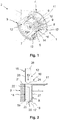
- FIG. 1 shows a structural unit 1, which is intended for mounting on a sanitary fitting 2.
- the assembly 1 has an operating element 3, by means of which an operating state of the sanitary fitting 2 can be adjusted.
- the assembly 1 has a valve body 4, which can be actuated via the operating element 3 such that a water outflow of the sanitary fitting 2 on or off.
- the control element 3 and the valve body 4 are rotatably connected to each other via two mutually corresponding positive-locking elements 5, 6.
- the first positive locking element 5 is a hollow cylinder 7 with a first toothing 8.
- the first toothing 8 is an internal toothing.
- the second positive locking element 6 is a cylinder 10 which is formed corresponding to the first positive locking element 5, so that the second positive locking element 6 can be arranged in the first positive locking element 5.
- the second positive locking element preferably has a second toothing 9, which is an external toothing.
- the first and second teeth 8, 9 are formed corresponding to each other.
- the control element 3 and the valve body 4 are rotatable about a rotation axis 11.
- the axis of rotation 11 preferably runs coaxially to the two form-locking elements 5, 6.
- the operating element 3 In order to connect the operating element 3 with the valve body 4, the first positive-locking element 5 of the operating element 3 is stretched onto the second positive-locking element 6 of the valve body 4.
- the operating element 3 has at least one axial securing unit 12.
- the axial securing unit 12 can generate an axial force 13 in the direction of the axis of rotation 11.
- the axial securing unit 12 has at least one bore 14.
- the bore 14 extends in the axial direction of the operating element 3.
- the bore 14 is radially spaced from the axis of rotation 11.
- the bore 14 is for receiving a locking pin 15 (see. Fig. 2 and 3 ), by means of which the axial force 13 can be generated, formed.
- the operating element 3 has a plurality of axial securing units 12 distributed in the circumferential direction.
- the axial securing unit 12 also has at least one deflection mechanism 16.
- the deflection mechanism 16 is designed to deflect the axial force 13 that can be generated by the axial securing unit 12 such that the first positive locking element 5 presses in the radial direction of the operating element 3 against the second positive locking element 6 of the valve body 4. The operating element 3 is thereby clamped substantially on the valve body 4.
- the deflection mechanism 16 has at least one first deflection bevel 17 for receiving and deflecting the axial force 13 that can be generated by the axial securing unit 12, in particular the securing pin 15.
- the deflection mechanism 16 shows FIG. 2 a section of the operating element 3, wherein the first deflection bevel 17 is arranged on a first bore part 18 of the bore 14.
- the first deflection bevel 17 is arranged on a valve body 4 facing the end of the control element 3 such that it is accessible to the locking pin 15.
- the bore 14 has a second bore part 19.
- the first bore part 18 is deflectable in the radial direction.
- the second bore part 19 is stationary.
- the two bore parts 18, 19 are at least partially separated by a separating recess 20 from each other.
- the first bore part 18 is movable relative to the second bore part 19 in the radial direction.
- the bore 14 has an internal thread 21 which extends over both bore parts 18, 19.
- the separating recess 20 extends axially in the bore 14 in the bore longitudinal direction, in particular substantially parallel to the axis of rotation 11.
- the separating recess 20 extends from a closed first bore end 22 in the direction of an open second bore end 23.
- the first bore end 22 is located on a valve body 4 (see. Fig. 1 ) facing away from the end of the bore 14.
- the open second bore end 23 is arranged on the valve body side.
- the locking pin 15 has at its bore-side end a second deflection bevel 24.
- the deflecting bevel 24 is formed substantially circumferentially on the locking pin 15, so that the locking pin has a tip.
- an external thread 25 is formed on the locking pin 15.
- the locking pin 15 preferably has a tool recess 26 at its end facing away from the second deflection bevel 24. To introduce the locking pin 15 in the bore 14, this is offset via the tool recess 26 in a rotational movement, so that the external thread 25 of the locking pin 15 engages in the internal thread 21 of the bore 14.
- the locking pin 15 is screwed so far into the bore 14 until the second deflection bevel 24 of the locking pin against the first deflection bevel 17 of the deflection mechanism 16, in particular of the first bore part 18, presses (see. Fig. 3 ).
- a first radius r 1 is formed between an outer wall 27 of the movable first bore part 18 and the rotation axis 11.
- the outer wall 27 essentially forms part of the first positive-locking element 5, in particular the inner toothing.
- the first radius r 1 is formed between the first bore part 18 and the rotation axis 11, when the locking pin 15 is not disposed in the bore 14.
- the first bore part 18 is not deflected when the locking pin 15 is not disposed in the bore 14.
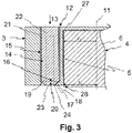
- FIG. 3 shows the operating element 3 with introduced locking pin 15.
- the locking pin 15 is screwed so far into the bore 14 until the second deflection bevel 24 of the locking pin 15 presses against the first deflection bevel 17 of the first bore part 18. Due to the axial force 13 of the securing pin 15, the first bore part 18 is pressed at least in the region of its first deflection slope 17 in the direction of the axis of rotation 11. The first bore part 18 is displaced in the region of the second bore end 23 of the separating recess 20 to the inside. Between the deflected part of the first bore part 18 and the rotation axis 11, a second radius r 2 is formed as a result of the radial deflection. The second radius r 2 is smaller than the first radius r 1 .
- the operating element 3 is arranged secured to the valve body 4.
- the deflection of the first bore part 18 is shown schematically.
- the first bore part 18 is deflected by the deflected axial force 13 in the direction of the axis of rotation 11.
- the second form-fitting element 6 is thereby slightly deformed in a pressure region 28, so that the expansion of the second form-fitting element 6 is reduced transversely to the axis of rotation.
- the two Positive locking elements 5, 6 are clamped against each other, so that the control element 3 can not be detached from the valve body 4.
- the locking pin 15 and the bore 14 are formed according to an alternative embodiment, not shown, each without the outer and / or inner thread 21, 25.
- the locking pin 15 is thereby pressed into the bore 14 and / or pressed until the second deflection bevel 24 presses against the first deflection bevel 17.
- the deflection mechanism 16 comprises only the locking pin 15, the second deflection bevel 24.
- an unillustrated stop is formed in the region of the open second bore end 23. The stop is substantially perpendicular to the axis of rotation 11.
- the axial force 13 of the locking pin 15 is at least as far introduced into the bore 14 that the second deflection bevel 24 of the locking pin 15 abuts against the stop.
- the stopper and the movable first bore member 18 the axial force 13 is deflected in the radial direction.
- the first positive locking element 5 thus presses against the second positive locking element 6, so that the operating element 3 is axially secured.
Landscapes
- Engineering & Computer Science (AREA)
- General Engineering & Computer Science (AREA)
- Physics & Mathematics (AREA)
- General Physics & Mathematics (AREA)
- Automation & Control Theory (AREA)
- Mechanical Engineering (AREA)
- Preventing Unauthorised Actuation Of Valves (AREA)
Applications Claiming Priority (1)
| Application Number | Priority Date | Filing Date | Title |
|---|---|---|---|
| DE102017115684.4A DE102017115684A1 (de) | 2017-07-12 | 2017-07-12 | Bedienelement sowie eine das Bedienelement aufweisende Baueinheit |
Publications (1)
| Publication Number | Publication Date |
|---|---|
| EP3428496A1 true EP3428496A1 (fr) | 2019-01-16 |
Family
ID=62816373
Family Applications (1)
| Application Number | Title | Priority Date | Filing Date |
|---|---|---|---|
| EP18180408.9A Withdrawn EP3428496A1 (fr) | 2017-07-12 | 2018-06-28 | Élément de commande ainsi qu'une unité structurale comprenant l'élément de commande |
Country Status (2)
| Country | Link |
|---|---|
| EP (1) | EP3428496A1 (fr) |
| DE (1) | DE102017115684A1 (fr) |
Cited By (1)
| Publication number | Priority date | Publication date | Assignee | Title |
|---|---|---|---|---|
| CN109848300A (zh) * | 2019-03-28 | 2019-06-07 | 优德精密工业(昆山)股份有限公司 | 一种旋转冲压机构 |
Citations (9)
| Publication number | Priority date | Publication date | Assignee | Title |
|---|---|---|---|---|
| US1519375A (en) * | 1923-04-04 | 1924-12-16 | Ternstedt Mfg Co | Handle assembly |
| US1877289A (en) * | 1931-04-28 | 1932-09-13 | Ternstedt Mfg Co | Handle assembly |
| US2191294A (en) * | 1937-05-01 | 1940-02-20 | Harper Wyman Mfg Company | Fastening means for detachably securing handles to operating shafts |
| US2516472A (en) * | 1946-11-30 | 1950-07-25 | Jr Ben F Mackeage | Coupling |
| AU516939B2 (en) * | 1976-04-08 | 1981-07-02 | Upl Group Ltd. | Tap handles and means for mounting same |
| EP2527951A2 (fr) * | 2011-05-19 | 2012-11-28 | BSH Bosch und Siemens Hausgeräte GmbH | Élément de commande pour un appareil ménager ainsi qu'appareil ménager avec un dispositif de commande doté d'un élément de commande |
| WO2014005688A1 (fr) * | 2012-07-03 | 2014-01-09 | Continental Automotive France | Dispositif de commande avec coaxialite optimisee |
| US20150345118A1 (en) * | 2014-05-28 | 2015-12-03 | Globe Union Industrial Corp. | Quick assembly structure of faucet handle base |
| US20150355668A1 (en) * | 2013-02-19 | 2015-12-10 | Continental Automotive France | Control device having pull-out resistance |
Family Cites Families (1)
| Publication number | Priority date | Publication date | Assignee | Title |
|---|---|---|---|---|
| CA2655523A1 (fr) | 2009-02-23 | 2010-08-23 | Globe Union Industrial Corp. | Structure d'ensemble de manette avec dispositif de fermeture |
-
2017
- 2017-07-12 DE DE102017115684.4A patent/DE102017115684A1/de active Pending
-
2018
- 2018-06-28 EP EP18180408.9A patent/EP3428496A1/fr not_active Withdrawn
Patent Citations (9)
| Publication number | Priority date | Publication date | Assignee | Title |
|---|---|---|---|---|
| US1519375A (en) * | 1923-04-04 | 1924-12-16 | Ternstedt Mfg Co | Handle assembly |
| US1877289A (en) * | 1931-04-28 | 1932-09-13 | Ternstedt Mfg Co | Handle assembly |
| US2191294A (en) * | 1937-05-01 | 1940-02-20 | Harper Wyman Mfg Company | Fastening means for detachably securing handles to operating shafts |
| US2516472A (en) * | 1946-11-30 | 1950-07-25 | Jr Ben F Mackeage | Coupling |
| AU516939B2 (en) * | 1976-04-08 | 1981-07-02 | Upl Group Ltd. | Tap handles and means for mounting same |
| EP2527951A2 (fr) * | 2011-05-19 | 2012-11-28 | BSH Bosch und Siemens Hausgeräte GmbH | Élément de commande pour un appareil ménager ainsi qu'appareil ménager avec un dispositif de commande doté d'un élément de commande |
| WO2014005688A1 (fr) * | 2012-07-03 | 2014-01-09 | Continental Automotive France | Dispositif de commande avec coaxialite optimisee |
| US20150355668A1 (en) * | 2013-02-19 | 2015-12-10 | Continental Automotive France | Control device having pull-out resistance |
| US20150345118A1 (en) * | 2014-05-28 | 2015-12-03 | Globe Union Industrial Corp. | Quick assembly structure of faucet handle base |
Cited By (2)
| Publication number | Priority date | Publication date | Assignee | Title |
|---|---|---|---|---|
| CN109848300A (zh) * | 2019-03-28 | 2019-06-07 | 优德精密工业(昆山)股份有限公司 | 一种旋转冲压机构 |
| CN109848300B (zh) * | 2019-03-28 | 2023-11-21 | 优德精密工业(昆山)股份有限公司 | 一种旋转冲压机构 |
Also Published As
| Publication number | Publication date |
|---|---|
| DE102017115684A1 (de) | 2019-01-17 |
Similar Documents
| Publication | Publication Date | Title |
|---|---|---|
| EP3717786B1 (fr) | Dispositif de compensation de tolérance avec sécurité par serrage | |
| EP2318723B1 (fr) | Agencement de fixation avec compensation des tolerances | |
| DE102019003546A1 (de) | Adapter für einen Antrieb und Antrieb | |
| EP1277971A1 (fr) | Cheville expansible imperdable | |
| EP2827006A1 (fr) | Système de rivet borgne | |
| EP4737748A1 (fr) | Élément de connexion et agencement de connexion | |
| AT393302B (de) | Vorrichtung zur verbindung zweier werkzeugteile | |
| DE102016012586B4 (de) | Lösbare Stielbefestigungskupplung für Arbeitsgeräte | |
| EP3115294B1 (fr) | Pince de traction-compression | |
| DE60204814T2 (de) | Befestigungmittel zum Verbinden von einem Maschinenteil mit einer Welle | |
| EP3807012B1 (fr) | Centrifugeuse | |
| DE10311572B4 (de) | Anordnung zur Verbindung eines rohrförmigen Elementes mit einem darin erstreckten Körper | |
| EP0846908B1 (fr) | Connection entre tube et composant. | |
| DE102018126391B4 (de) | Fahrzeugsitzelement für einen Fahrzeugsitz mit einer Restfederwegverstelleinrichtung | |
| EP4012200B1 (fr) | Boulon d'encliquetage sollicité par ressort | |
| DE102009051540A1 (de) | Selbstsichernde Einstelleinrichtung, Fahrzeuglenkung und Verfahren zum Einstellen eines Spiels eines Druckstück in einer Fahrzeuglenkung | |
| EP2187076B1 (fr) | Couplage d'arbre creux | |
| DE102017009288B4 (de) | Konuslager als Elastomer-Metall-Lager | |
| DE102017115684A1 (de) | Bedienelement sowie eine das Bedienelement aufweisende Baueinheit | |
| EP4621271A1 (fr) | Adaptateur pour raccorder un moyen d'entraînement à un robinet d'arrêt actionnable manuellement et système constitué d'un tel adaptateur et d'un robinet d'arrêt actionnable manuellement | |
| WO1994018470A1 (fr) | Dispositif de fixation pour freins a disques | |
| DE102014224561B3 (de) | Spannfutter | |
| DE102005003770B3 (de) | Verbindung einer Bremse mit einer Achse eines Fahrzeuges | |
| DE102018128252A1 (de) | Spannbolzen zum lösbaren Verbinden von Bauteilen | |
| EP3626898B1 (fr) | Système de tubes profilés |
Legal Events
| Date | Code | Title | Description |
|---|---|---|---|
| PUAI | Public reference made under article 153(3) epc to a published international application that has entered the european phase |
Free format text: ORIGINAL CODE: 0009012 |
|
| AK | Designated contracting states |
Kind code of ref document: A1 Designated state(s): AL AT BE BG CH CY CZ DE DK EE ES FI FR GB GR HR HU IE IS IT LI LT LU LV MC MK MT NL NO PL PT RO RS SE SI SK SM TR |
|
| AX | Request for extension of the european patent |
Extension state: BA ME |
|
| STAA | Information on the status of an ep patent application or granted ep patent |
Free format text: STATUS: THE APPLICATION IS DEEMED TO BE WITHDRAWN |
|
| 18D | Application deemed to be withdrawn |
Effective date: 20190717 |