EP1715238A2 - Doppelhalsiger Pulsationsdämpfer für einen Verdichter - Google Patents
Doppelhalsiger Pulsationsdämpfer für einen Verdichter Download PDFInfo
- Publication number
- EP1715238A2 EP1715238A2 EP06251515A EP06251515A EP1715238A2 EP 1715238 A2 EP1715238 A2 EP 1715238A2 EP 06251515 A EP06251515 A EP 06251515A EP 06251515 A EP06251515 A EP 06251515A EP 1715238 A2 EP1715238 A2 EP 1715238A2
- Authority
- EP
- European Patent Office
- Prior art keywords
- cross
- sectional area
- chamber
- pulsation dampener
- inlet
- Prior art date
- Legal status (The legal status is an assumption and is not a legal conclusion. Google has not performed a legal analysis and makes no representation as to the accuracy of the status listed.)
- Granted
Links
Images



Classifications
-
- F—MECHANICAL ENGINEERING; LIGHTING; HEATING; WEAPONS; BLASTING
- F04—POSITIVE - DISPLACEMENT MACHINES FOR LIQUIDS; PUMPS FOR LIQUIDS OR ELASTIC FLUIDS
- F04C—ROTARY-PISTON, OR OSCILLATING-PISTON, POSITIVE-DISPLACEMENT MACHINES FOR LIQUIDS; ROTARY-PISTON, OR OSCILLATING-PISTON, POSITIVE-DISPLACEMENT PUMPS
- F04C29/00—Component parts, details or accessories of pumps or pumping installations, not provided for in groups F04C18/00 - F04C28/00
- F04C29/06—Silencing
- F04C29/061—Silencers using overlapping frequencies, e.g. Helmholtz resonators
-
- F—MECHANICAL ENGINEERING; LIGHTING; HEATING; WEAPONS; BLASTING
- F04—POSITIVE - DISPLACEMENT MACHINES FOR LIQUIDS; PUMPS FOR LIQUIDS OR ELASTIC FLUIDS
- F04B—POSITIVE-DISPLACEMENT MACHINES FOR LIQUIDS; PUMPS
- F04B39/00—Component parts, details, or accessories, of pumps or pumping systems specially adapted for elastic fluids, not otherwise provided for in, or of interest apart from, groups F04B25/00 - F04B37/00
- F04B39/0027—Pulsation and noise damping means
- F04B39/0055—Pulsation and noise damping means with a special shape of fluid passage, e.g. bends, throttles, diameter changes, pipes
-
- F—MECHANICAL ENGINEERING; LIGHTING; HEATING; WEAPONS; BLASTING
- F16—ENGINEERING ELEMENTS AND UNITS; GENERAL MEASURES FOR PRODUCING AND MAINTAINING EFFECTIVE FUNCTIONING OF MACHINES OR INSTALLATIONS; THERMAL INSULATION IN GENERAL
- F16L—PIPES; JOINTS OR FITTINGS FOR PIPES; SUPPORTS FOR PIPES, CABLES OR PROTECTIVE TUBING; MEANS FOR THERMAL INSULATION IN GENERAL
- F16L55/00—Devices or appurtenances for use in, or in connection with, pipes or pipe systems
- F16L55/04—Devices damping pulsations or vibrations in fluids
- F16L55/041—Devices damping pulsations or vibrations in fluids specially adapted for preventing vibrations
Definitions
- the present invention relates to pulsation dampeners used on oil free screw compressors to suppress the pressure pulsations generated by the compressor airend.
- a pulsation dampener reduces the mechanical vibrations in the downstream piping system caused by the pressure pulsations originating from the outlet of the compressor. If these pulsations are left undamped, the pulsations can damage the piping system, coolers, moisture separator, valves and ancillary equipment. Pulsation dampeners reduce noise heard from the compressor by reducing the pressure pulsations inside the piping system.
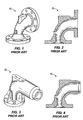
- venturis 10 and 15 shown in FIGS. 1-2 and 3-4, respectively, are currently used to reduce pressure pulsations.
- a venturi is a high pass acoustical device.
- a high pass device attenuates pressure pulsations having low frequencies while allowing high frequency pressure pulsations to pass through the device.
- Oil free compressor applications require a low pass acoustical device.
- a low pass acoustical device attenuates the high frequencies and allows low frequencies to pass through the device.
- the venturi does offer some attenuation at the higher frequencies, but the attenuation is not sufficient (i.e., does not cover broad ranges of frequencies) to reduce all of the pulsations. Insufficient attenuating of the high frequency pressure pulsations by the venturi have resulted in high noise levels, damage to check valves, cooler failures and ringing piping systems.
- the pulsation dampener can include a body having an inlet end and an outlet end.
- the inlet end can include an inlet having a first cross-sectional area
- the outlet end can include an outlet.
- the pulsation dampener can further include a fluid path defined at least partially by the body and extending between the inlet and the outlet.
- the fluid path can include a first contracting chamber positioned adjacent the inlet and having a second cross-sectional area, a first expansion chamber positioned adjacent the first contracting chamber and having a third cross-sectional area, and a second contracting chamber positioned adjacent the first expansion chamber and having a fourth cross-sectional area.
- the fluid path can be configured such that the second cross-sectional area is less than the first cross-sectional area and the third cross-sectional area, and the fourth cross-sectional area is less than the third cross-sectional area.
- a pulsation dampener for receiving a fluid medium comprising pressure pulsations.
- the pulsation dampener can include a body having an inner surface, an inlet, and an outlet.
- the pulsation dampener can further include a fluid path defined at least partially by the inner surface of the body.
- the fluid path can include a first chamber in fluid communication with the inlet and having a first cross-sectional area, a second chamber positioned adjacent the first chamber and having a second cross-sectional area different from the first cross-sectional area, and a third chamber in fluid communication with the outlet and positioned adjacent the second chamber opposite the first chamber.
- the third chamber can include a third cross-sectional area different from the second cross-sectional area.
- the fluid path can be configured such that the second cross-sectional area is greater than the first cross-sectional area and the third cross-sectional area.
- Some embodiments of the present invention provide a pulsation dampener for receiving a fluid medium comprising pressure pulsations.
- the pulsation dampener can include a body having an inner surface, an inlet end, and an outlet end.
- the inlet end can include an inlet having a first cross-sectional area, and the outlet end can include an outlet.
- the pulsation dampener can further include a fluid path defined at least partially by the inner surface of the body and extending between the inlet and the outlet.
- the fluid path can include a first contracting chamber positioned adjacent the inlet and having a second cross-sectional area, a first expansion chamber positioned adjacent the first contracting chamber opposite the inlet and having a third cross-sectional area, a second contracting chamber positioned adjacent the first expansion chamber opposite the first contracting chamber and having a fourth cross-sectional area, and a second expansion chamber positioned adjacent the second contracting chamber opposite the first expansion chamber and having a fifth cross-sectional area.
- the fluid path can be configured such that the second cross-sectional area is less than the first cross-sectional area and the third cross-sectional area, and the fourth cross-sectional area is less than the third cross-sectional area and the fifth cross-sectional area.
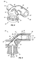
- the pulsation dampener 20 includes a body 22 having an inlet end 24 and an outlet end 26, and an inner surface 17.
- the inner surface 17 of the body 22 defines a fluid path 21 that extends between the inlet end 24 and the outlet end 26.
- the dampener body 22 has an approximately 90-degree angle configuration such that the inlet end 24 is substantially perpendicular to the outlet end 26, and the fluid flow through the fluid path 21 changes direction by about 90 degrees.
- the body may have other configurations.
- the body 22 includes a 45-degree configuration, or a straight configuration. In a straight configuration, the inlet end 24 is substantially parallel to the outlet end 26, and the fluid flow through the fluid path 21 does not change directions.
- the body 22 includes a one or more ribs 19 positioned to enhance structural integrity of the body 22 and pulsation dampener 20.
- the ribs 19 can be positioned on the outside of the body 22 adjacent narrow regions of the fluid path 21 (e.g., contracting chambers, as described below), as shown in FIG. 5, to enhance the structural integrity of the body 22 in those narrow regions.
- the dampener body 22 is a cast structure and may be provided with a port 33 in fluid communication with the fluid path 21, positioned to assist in clean out of the body 22, and particularly, in removal of media used in the casting process.
- the port 33 can be plugged after manufacture.
- the pulsation dampener 20 is a first stage dampener and has a flange 23 at the inlet end 24 and a flange 32 at the outlet end 26 for connection to the intended piping system.
- the inlet end 24 has an inlet 25 having an inlet cross-sectional area S 1 .
- a fluid medium containing pressure pulsations for example, compressed air from an oil free compressor airend, is directed into fluid path 21 of the pulsation dampener 20 through the inlet 25.
- the fluid medium is thereafter contracted as it travels through a first contracting chamber 27 having a cross-sectional area S 1 (e.g., the minimum cross-sectional area within the first contracting chamber 27) that is less than the inlet cross-sectional area S 1 .
- the fluid medium travels into a first expansion chamber 28 having a cross-sectional area S 2 (e.g., the maximum cross-sectional area within the first expansion chamber 28) that is greater than the cross-sectional area S 1 of the first contracting chamber 27.
- the fluid medium is again contracted as it flows to a second contracting chamber 29 having a cross-sectional area S 3 (e.g., the minimum cross-sectional area within the second contracting chamber 29) that is less than the cross-sectional area S 2 of the first expansion chamber 28.
- the fluid medium flows into a second expansion chamber 30 having a cross-sectional area S 4 (e.g., the maximum cross-sectional area of the second expansion chamber 30) that is greater than the cross-sectional area S 3 of the second contracting chamber 29.
- a cross-sectional area S 4 e.g., the maximum cross-sectional area of the second expansion chamber 30
- the fluid medium exits the dampener 20 via the dampener outlet 31 to a downstream piping system (not shown).
- the outlet 31 has an outlet cross-sectional area S 0 .
- the outlet cross-sectional area S 0 is approximately equal to the cross-sectional area S 4 of the second expansion chamber 30.
- the inside cross-sectional areas S 1 , S 2 , S 3 , and S 4 and the lengths L 1 , L 2 , L 3 and L 4 of the first contracting chamber 27, the first expansion chamber 28, the second contracting chamber 29, and the second expansion chamber 30, respectively, are chosen to provide the desired dampening of the fluid medium. Dampening can be measured in terms of transmission loss.
- the transmission matrix is the acoustical power difference between the incident and transmittal waves assuming an anechoic termination (i.e., without echo), which will be described in greater detail below.
- the pulsation dampener 20 should not incur too great of a pressure drop across the pulsation dampener 20 to achieve the desired transmission loss. Balancing the transmission loss with the pressure drop allows for attenuation of desired frequencies without diminishing fluid output from the pulsation dampener 20.
- T ′ [ T 11 T 12 T 21 T 22 ] [ T 11 T 12 T 21 T 22 ] [ T 11 T 12 T 21 T 22 ]
- T ′ [ T 11 T 12 T 21 T 22 ] [ T 11 T 12 T 21 T 22 ]
- T ′ [ T 11 T 12 T 21 T 22 ] [ T 11 T 12 T 21 T 22 ]
- T ′ [ T 11 T 12 T 21 T 22 ] [ T 11 T 12 T 21 T 22 ]
- T 11 T 12 T 21 T 22 ] T 11 T 12 T 21 T 22 ]
- the transmission loss denoted TL is the acoustical power loss between the incident and transmitted waves of an anechoically terminated silencer, or pulsation dampener.
- T L 20 log 10 [ T ′ 11 + S 2 c ⁇ T ′ 12 + c S 1 ⁇ T ′ 21 + T ′ 22 2 ]
- S 1 is the area at the inlet to the pulsation dampener 20
- S 0 is the terminating area of the pulsation dampener (i.e., the cross-sectional area of the outlet 31, as described above).
- the TL transmission loss
- S i + 1 + S i 10 log 10 ( S i + 1 + S i ) 2 / ( 4 S i + 1 S i ) wherein S i + 1 and S i represent the pipe cross-sectional area changes at each junction, as in FIG. 7.
- the cross-sectional areas of various portions of the fluid path 21 can be represented by circles, and the cross-sectional areas can therefore be calculated from the respective diameters of such circles.
- T L 10 log 10 ( S i + 1 + S i ) 2 / ( 4 S i + 1 S i ) .
- the neck lengths L 1 , L 2 , L 3 and L 4 determine the frequency at which the transmission loss is greatest, and the cross-sectional areas S i and S i +1 determine the amplitude of that transmission loss.
- a more exact calculation can be made using the transmission matrix. Given the complexity of the pulsation dampener 20, a numerical method is preferably used to obtain the precise sizing.
- FIGS. 8 and 9 illustrate another pulsation dampener 20' according to the present invention, wherein like numerals represent like elements.
- the pulsation dampener 20' shares many of the same elements and features described above with reference to the illustrated embodiment of FIGS. 5-7. Accordingly, elements and features corresponding to elements and features in the illustrated embodiment of FIGS. 8 and 9 are provided with the same reference numerals followed by a prime sign (e.g., 20', 21', 22', etc.). Reference is made to the description accompanying FIGS. 5-7 for a more complete description of the features and elements (and alternatives to such features and elements) of the embodiment illustrated in FIGS. 8 and 9.
- the dampener 20' can have various configurations to facilitate connection in various piping systems.
- the dampener 20' may be a second stage dampener with a dampener body 22' having a straight outlet end 26' with a straight fitting 32'.
- Other configurations are also contemplated.
- the dampener 20, 20' mismatches acoustical impedances by contracting then expanding the fluid.
- the expansion volumes act as resonators, or resonating volumes, for attenuating high frequencies.
- a desired acoustical performance is achieved (e.g., a desired attenuation level over a desired frequency range) without requiring that the cross-sectional area of the inlet 25, 25' be significantly smaller than pipes that feed the inlet 25, 25' (e.g., an outlet from a compressor or pipes in fluid communication with an outlet of a compressor).
- the pulsation dampener 20, 20' employs a smooth, contoured inner surface 17, 17' of the body 22, 22' to inhibit impinging of the fluid medium on solid surfaces.
- Such contouring of the inner surface 17, 17', in combination with the shape of the fluid path 21, allows for the above-mentioned acoustical performance while substantially reducing the pressure drop in the fluid medium as it passes through the pulsation dampener 20, 20'.
- the pulsation dampeners 20 and 20' of the present invention attenuate frequencies in the range of less than about 5000 Hz. In other words, the transmission loss achieved by the pulsation dampeners 20 and 20' is sufficiently large in this frequency range. In some embodiments, the pulsation dampeners 20 and 20' attenuate frequencies in the range of about 500 Hz to about 5000 Hz. In some embodiments, the pulsation dampeners 20 and 20' attenuate frequencies in the range of about 800 Hz to about 5000 Hz.
- the pulsation dampeners 20 and 20' of the present invention provide at least about 20 dB of attenuation in pressure pulsations in having a frequency ranging from about 500 Hz to about 5000 Hz. In some embodiments, the pulsation dampeners 20 and 20' provide between about 20 dB and 40 dB of attenuation in pressure pulsations having a frequency ranging from about 500 Hz to about 5000 Hz.
- the geometry of the pulsation dampeners 20 and 20' of the present invention can be precisely controlled to achieve the desired transmission loss and attenuation across a desired range of frequencies, as described above.
- NR noise reduction index
- TL transmission loss index
- FIGS. 10 and 11 show a comparison of the P1/P2 (i.e., the ratio of the sound pressure at the inlet to the sound pressure at the outlet, which is related to NR) and TL prediction for prior art venturis 10 and 15.
- TL is a widely accepted indicator of a dampener's performance
- TL is used to compare the performance of the prior art venturis 10 and 15 with the pulsation dampeners 20 and 20' of the present invention, as illustrated in FIGS. 10-13 and described below.
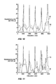
- FIG. 10 illustrates a transmission loss curve 50 and a pressure drop curve 60 through the prior art venturi 10 illustrated in FIGS. 1 and 2 for frequencies ranging from 0 to 5000 Hz.
- the transmission loss 50 through the venturi 10 varies greatly depending on frequency, and exhibits many "dips" of greatly reduced transmission loss at various frequencies.
- a first "dip” in transmission loss through the venturi 10 occurs at about 900 Hz.
- the venturi 10 would be a poor pulsation dampener for airflow having a frequency of about 900 Hz.
- the venturi 10 is not an effective or useful means to dampen pulsations across this frequency range.
- the venturi 10 may effectively attenuate pulsations for very narrow frequency ranges (e.g, from about 975 Hz to about 1000 Hz), but would not function robustly as a pulsation dampener according to the present invention.
- FIG. 11 illustrates a transmission loss curve 70 and a pressure drop curve 80 through the prior art venturi 15 illustrated in FIGS. 3 and 4 for frequencies ranging from 0 to 5000 Hz.
- the transmission loss 70 through the venturi 15 varies greatly depending on frequency, and exhibits many "holes” and “dips” of zero or greatly reduced transmission loss, respectively, at various frequencies.
- a first "hole” in transmission loss occurs at about 1700 Hz for the venturi 15, and a "dip” occurs at about 2250 Hz.
- the venturi 15 illustrated in FIGS. 3 and 4 is not an effective pulsation dampener at frequencies ranging from 0 to 5000 Hz.
- the venturi 15 may only effectively attenuate pulsations occurring at very narrow ranges of frequencies (e.g., from about 975 to about 1000 Hz).
- FIG. 12 illustrates a transmission loss curve 90 for the pulsation dampener 20 illustrated in FIGS. 5-7 for frequencies ranging from 0 to 5000 Hz.
- the transmission loss 90 achieved by the pulsation dampener 20 occurs over a large range of frequencies.
- the transmission loss curve experiences a "hole” around about 2500 Hz, a first "dip” around about 3250 Hz, and a second "dip” around about 4250 Hz.
- the transmission loss is at least about 10 over frequencies ranging from about 500 to about 2300 Hz, from about 2800 to about 3200 Hz, from about 3300 to about 4200 Hz, and from about 4300 to about 4600 Hz.
- the lengths (e.g., L 1 , L 2 , L 3 and L 4 ) of the various sections of the pulsation dampener 20 can be varied to position any "holes" or “dips" in transmission loss at frequencies that are least important or relevant to a specific application using the relationship between neck length and frequency given above.
- the pulsation dampener 20 also achieved a lower pressure drop than that incurred with the prior art venturis 10 and 15.
- Fluid medium is allowed to communicate between the outlet of a compressor (not shown) that is coupled to the inlet end 24 of the body 22, and in fluid communication with the inlet 25.
- fluid medium is further allowed to flow through the fluid path 21 defined by the body 22 of the pulsation dampener 20 to the outlet 31 without impinging on any solid surfaces, because the inner surface 17 is defined by rounded or contoured surfaces.
- a first junction 92 is defined between the first contracting chamber 27 and the first expansion chamber 28
- a second junction 94 is defined between the first expansion chamber 28 and the second contracting chamber 29
- a third junction 96 is defined between the second contracting chamber 29 and the second expansion chamber 30.
- the inner surface 17 at, or adjacent, each of the junctions 92, 94 and 96 is substantially smooth and contoured to inhibit impinging the fluid medium on any solid surfaces as it flows through the fluid path 21, which reduces the pressure drop across each junction 92, 94 of 96, and across the entire dampener 20.
- FIG. 13 illustrates a transmission loss curve 100 for the pulsation dampener 20' illustrated in FIGS. 8-9 for frequencies ranging from 0 to 5000 Hz.
- the transmission loss 100 achieved by the pulsation dampener 20' occurs over a large range of frequencies.
- the transmission loss curve experiences a "dip" around about 1825 Hz.
- the transmission loss is at least about 10 dB over frequencies ranging from about 400 Hz to about 1820 Hz, and from about 1840 Hz to about 5000 Hz.
- much greater ranges of frequencies are attenuated using the pulsation dampener 20' than the prior art venturis 10 and 15.
- the specific geometry of the pulsation dampener 20' can be controlled using the equations and relationships described above to position any "holes” or “dips” in transmission loss at frequencies that are least important or relevant to a specific application. Furthermore, the pulsation dampener 20' also achieved a lower pressure drop than that incurred with the prior art venturis 10 and 15, due, at least in part, to the inner surface 17' being rounded and contoured appropriately.
- a pulsation dampener e.g., used with an oil-free screw compressor
- the pressure pulsation in the fluid can be described as slugs of fluid (e.g., air) that are discharged from the compressor each time rotors in the compressor open and close.
- fluid flow including the pulsations, is fluid dynamic by nature, and these pressure pulsations travel at the convective speed of the fluid in the form of flow structures that can be described as vortices.
- Pressure pulsations in the fluid can be measured at the discharge port of the compressor.
- these pressure pulsations include a mean pressure component, and a fluctuating pressure component.
- the mean pressure component can be about 100 psig, and the fluctuating pressure component can vary by ⁇ 30 psi.
- the primary frequency for the fluctuating pressure component is approximately the frequency at which the discharge port of the compressor opens and closes. In some embodiments, this frequency is greater than about 500 Hz. Higher frequencies can also be present in the fluid stream, because the vortices (or similar flow structures) can divide into smaller vortices, and produce harmonic components.
- the amplitude of the fluctuating pressure component of the pressure pulsation for the 100-psig compressor can be from about 70 psig to about 130 psig.
- the pulsation dampeners 20 and 20' of the present invention is to convert the fluid dynamic pulsations described above into acoustic pulsations by effectively squeezing the discharge vortices.
- the fluid pulsation that is discharged from the compressor, that enters the pulsation dampener 20 or 20' can be decomposed into two components: an acoustic component that has a wavelength, ⁇ a , that travels at the speed of sound, c, and a fluid dynamic component that has a wavelength, ⁇ g , that travels at the convective velocity of the gas, u g .
- the Mach number is less than 0.2, which requires the acoustic wavelength to be greater than the fluid dynamic instability wavelength (i.e., ⁇ a > ⁇ g ) for a given frequency.
- the fluid dynamic instability wavelength i.e., ⁇ a > ⁇ g
- the pressure pulsations transition from organized vortical structures to small-scale turbulent structures. As this transition occurs, the pulsations can become mostly acoustic rather than fluid dynamic.
- the pulsation dampeners 20 and 20' of the present invention accomplish this transition both as a fluid dynamic device and as an acoustic device.
- the pulsation dampeners 20 and 20' of the present invention can provide several results.
- First, the pulsation dampeners 20 and 20' can rapidly convert the fluid dynamic pressure pulsations discharged from the airend of a compressor to an acoustic pressure pulsation.
- Second, the pulsation dampeners 20 and 20' can reduce the acoustic pressure pulsations by using contraction and expansion chambers (such as those described above and illustrated in FIGS. 5-9).
- the pulsation dampeners 20 and 20' can reduce the pressure pulsations in the fluid stream by using a contoured fluid path 21 or 21' (as defined by the inner surface 17 or 17' of the pulsation dampener 20 or 20') that minimizes the amount of mean pressure loss (i.e., the fluid dynamic component of the pressure pulsations).
- the pulsation dampeners 20 and 20' of the present invention can be designed to accomplish the desired attenuation of pulsations using acoustic and computational fluid dynamic computer software to make the numerical predictions.
Landscapes
- Engineering & Computer Science (AREA)
- General Engineering & Computer Science (AREA)
- Mechanical Engineering (AREA)
- Applications Or Details Of Rotary Compressors (AREA)
- Pipe Accessories (AREA)
- Compressor (AREA)
Applications Claiming Priority (1)
| Application Number | Priority Date | Filing Date | Title |
|---|---|---|---|
| US11/111,269 US7549509B2 (en) | 2005-04-21 | 2005-04-21 | Double throat pulsation dampener for a compressor |
Publications (3)
| Publication Number | Publication Date |
|---|---|
| EP1715238A2 true EP1715238A2 (de) | 2006-10-25 |
| EP1715238A3 EP1715238A3 (de) | 2008-02-13 |
| EP1715238B1 EP1715238B1 (de) | 2009-02-11 |
Family
ID=36685985
Family Applications (1)
| Application Number | Title | Priority Date | Filing Date |
|---|---|---|---|
| EP20060251515 Expired - Lifetime EP1715238B1 (de) | 2005-04-21 | 2006-03-22 | Doppelhalsiger Pulsationsdämpfer für einen Verdichter |
Country Status (4)
| Country | Link |
|---|---|
| US (2) | US7549509B2 (de) |
| EP (1) | EP1715238B1 (de) |
| DE (1) | DE602006005091D1 (de) |
| ES (1) | ES2319923T3 (de) |
Cited By (8)
| Publication number | Priority date | Publication date | Assignee | Title |
|---|---|---|---|---|
| EP2461079A1 (de) * | 2010-12-03 | 2012-06-06 | Levitronix GmbH | Durchflussmesser |
| WO2013139772A1 (de) * | 2012-03-20 | 2013-09-26 | Bitzer Kühlmaschinenbau Gmbh | Kältemittelverdichter |
| US8740581B2 (en) | 2010-03-30 | 2014-06-03 | Southern Gas Association Gas Machinery Research Council | Pressure recovery insert for reciprocating gas compressor |
| EP1978259A3 (de) * | 2007-04-05 | 2014-07-30 | GHH-RAND Schraubenkompressoren GmbH | Schalldämpfer zur Verwendung an einem Kompressor |
| EP2199613A3 (de) * | 2008-12-18 | 2015-03-25 | Nuovo Pignone Holding S.P.A. | Verfahren und Apparatus zur akkustischen Prüfung eines Verdichters |
| US10180140B2 (en) | 2016-09-30 | 2019-01-15 | Ingersoll-Rand Company | Pulsation damper for compressors |
| EP3042080B1 (de) | 2013-09-05 | 2019-05-08 | Atlas Copco Airpower | Verdichtervorrichtung |
| US10682588B2 (en) | 2017-10-18 | 2020-06-16 | Ingersoll-Rand Industrial U.S., Inc. | Modular heat exchanger, moisture separator and pulsation dampener for a multi-stage fluid compressor |
Families Citing this family (8)
| Publication number | Priority date | Publication date | Assignee | Title |
|---|---|---|---|---|
| US7717135B2 (en) * | 2006-02-03 | 2010-05-18 | Yh America, Inc. | Energy attenuation device |
| KR101376619B1 (ko) * | 2008-04-04 | 2014-03-20 | 엘지전자 주식회사 | 스크롤 압축기 |
| US9739290B2 (en) | 2014-01-16 | 2017-08-22 | Ingersoll-Rand Company | Compressor system with pressure pulsation dampener and check valve |
| US9951761B2 (en) * | 2014-01-16 | 2018-04-24 | Ingersoll-Rand Company | Aerodynamic pressure pulsation dampener |
| KR102080623B1 (ko) * | 2015-03-06 | 2020-02-25 | 한온시스템 주식회사 | 전동압축기 |
| DE202016001950U1 (de) * | 2016-03-30 | 2017-07-03 | Leybold Gmbh | Vakuumpumpe |
| WO2020112450A1 (en) * | 2018-11-27 | 2020-06-04 | Smith & Burgess Process Safety Consulting | Resonator for a pressurized fluid system |
| US11674536B2 (en) * | 2020-12-14 | 2023-06-13 | Caterpillar Inc. | Guide element for hydraulic fluid |
Family Cites Families (70)
| Publication number | Priority date | Publication date | Assignee | Title |
|---|---|---|---|---|
| US1611475A (en) * | 1922-03-23 | 1926-12-21 | Maxim Silencer Co | Silencer |
| US1811762A (en) | 1929-05-08 | 1931-06-23 | Burgess Lab Inc C F | Exhaust muffler |
| US2046193A (en) | 1931-01-03 | 1936-06-30 | Burgess Lab Inc C F | Muffler |
| US2073951A (en) | 1935-12-09 | 1937-03-16 | Servais Services Ltd | Silencer for gaseous currents |
| FR841390A (fr) | 1938-01-21 | 1939-05-17 | Dispositif silencieux pour pot d'échappement de moteurs de véhicules automobiles et autres applications | |
| US2748753A (en) * | 1950-08-08 | 1956-06-05 | Snecma | Boilers |
| US2950775A (en) | 1958-01-13 | 1960-08-30 | Aro Equipment Corp | Exhaust noise reducing and air diffusing means for pneumatic motors |
| US3028551A (en) | 1958-05-05 | 1962-04-03 | Collins Radio Co | Digital phase storage circuit |
| US2966138A (en) | 1958-05-12 | 1960-12-27 | Robert C Quackenbush | Muffler construction for portable pneumatic tool |
| US2950951A (en) * | 1958-07-28 | 1960-08-30 | Phillips Petroleum Co | Carbonate leach uranium milling process |
| US3208551A (en) | 1963-11-18 | 1965-09-28 | Carls William | Combined air muffler and metering valve with replaceable cartridge |
| US3299781A (en) | 1964-12-04 | 1967-01-24 | Ingersoll Rand Co | Air inlet and exhaust manifold |
| US3384200A (en) | 1967-03-16 | 1968-05-21 | Gardner Denver Co | Exhaust muffler for pneumatic tool |
| US3526293A (en) * | 1968-06-13 | 1970-09-01 | Gardner Denver Co | Muffler for fluid actuated tool |
| US3563213A (en) * | 1968-06-27 | 1971-02-16 | K M F Dev Corp | Internal combustion engine exhaust system |
| US3628627A (en) * | 1970-10-02 | 1971-12-21 | Vacu Blast Corp | Silencer for air-blasting gun |
| US3608666A (en) * | 1970-11-17 | 1971-09-28 | Karl Borje Olsson | Silencer |
| US3823795A (en) | 1973-05-30 | 1974-07-16 | Black & Decker Mfg Co | Air tool muffler |
| US3880245A (en) | 1973-11-21 | 1975-04-29 | Chicago Pneumatic Tool Co | Exhaust noise attenuating system with muffler for pneumatic tools |
| US3981378A (en) | 1974-10-16 | 1976-09-21 | Horn Construction Co., Inc. | Muffler for pile driving apparatus |
| DE2516626C2 (de) | 1975-04-16 | 1977-04-28 | Freudenberg Carl Fa | Schalldaempfer fuer ausstroemende druckgase |
| US4015683A (en) | 1975-12-29 | 1977-04-05 | Purex Corporation Ltd. | Noise suppressor for vacuum sweeper and the like |
| US4184564A (en) | 1977-08-29 | 1980-01-22 | Trainor John B | Combination muffler and air filter |
| US4134472A (en) | 1977-08-29 | 1979-01-16 | Trainor John B | Combination muffler and air filter |
| US4205732A (en) | 1979-03-07 | 1980-06-03 | Ingersoll-Rand Company | Muffler for portable pneumatic tool |
| US4258798A (en) | 1979-03-09 | 1981-03-31 | Rockwell International Corporation | Air passages for pneumatic tools |
| US4258799A (en) | 1979-11-27 | 1981-03-31 | Dresser Industries, Inc. | Inlet control valve |
| US4628528A (en) | 1982-09-29 | 1986-12-09 | Bose Corporation | Pressure wave transducing |
| US4690245A (en) * | 1983-03-17 | 1987-09-01 | Stemco, Inc. | Flattened venturi, method and apparatus for making |
| SE460348B (sv) | 1985-12-23 | 1989-10-02 | Atlas Copco Ab | Pneumatisk mutterdragare med tryckregulator |
| US4693339A (en) * | 1986-10-16 | 1987-09-15 | Newport News Shipbuilding And Dry Dock Company | Muffler for gas inducting machinery generating low frequency noise |
| US5123501A (en) * | 1988-10-21 | 1992-06-23 | Donaldson Company, Inc. | In-line constricted sound-attenuating system |
| US4934482A (en) | 1989-07-07 | 1990-06-19 | Ultra-Precision Manufacturing, Ltd. | Pulse damper |
| US5133647A (en) | 1989-07-07 | 1992-07-28 | Ultra-Precision Manufacturing, Ltd. | Pulse damper |
| US4936413A (en) * | 1989-07-10 | 1990-06-26 | Siemens-Bendix Automotive Electronics Limited | In-line noise attenuation device for a gas conduit |
| FR2656038A1 (fr) | 1989-12-20 | 1991-06-21 | Devil | Sortie d'echappement a venturi. |
| US5244521A (en) | 1991-05-31 | 1993-09-14 | Ligman Gary A | Pneumatic tool muffler system |
| US5183974A (en) * | 1992-04-03 | 1993-02-02 | General Motors Corporation | Gas pulsation attenuator for automotive air conditioning compressor |
| DE4238352C1 (de) | 1992-11-13 | 1994-02-17 | Freudenberg Carl Fa | Luftschalldämpfer |
| US6278789B1 (en) | 1993-05-06 | 2001-08-21 | Bose Corporation | Frequency selective acoustic waveguide damping |
| US5418339A (en) | 1993-11-04 | 1995-05-23 | Minnesota Mining And Manufacturing Company | Pneumatic tool having noise reducing muffling structure |
| FI94903C (fi) * | 1994-03-09 | 1995-11-10 | Neles Jamesbury Oy | Menetelmä kaasuvirtauksen kuristamisen aiheuttaman melun vaimentamiseksi ja kaasuvirtauskanavalla varustettu laite |
| US5588903A (en) | 1994-08-08 | 1996-12-31 | Indresco Inc. | Ergonomic power tool |
| US5821475A (en) * | 1994-09-20 | 1998-10-13 | The United States Of America As Represented By The Secretary Of The Navy | Venturi muffler with variable throat area |
| SE508959C2 (sv) * | 1995-02-24 | 1998-11-16 | Volvo Ab | Ljuddämpare för deplacementkompressorer |
| US5559310A (en) | 1995-04-26 | 1996-09-24 | Ingersoll-Rand Company | Muffler for air operated reciprocating pumps |
| US6427782B2 (en) | 1995-06-07 | 2002-08-06 | The William J. Brady Loving Trust | Noise suppression drilling system |
| US5687802A (en) | 1995-09-21 | 1997-11-18 | Chicago Pneumatic Tool Company | Power hand tool with rotatable handle |
| BE1009815A5 (nl) | 1995-11-16 | 1997-08-05 | Atlas Copco Airpower Nv | Pulsatiedemper of akoestisch uitlaatstuk voor een kompressor en kompressor hiermee uitgerust. |
| JP3883604B2 (ja) | 1996-04-24 | 2007-02-21 | 株式会社共立 | 消音装置付ブロワパイプ |
| JP3029092B2 (ja) | 1996-05-21 | 2000-04-04 | 羊太郎 多賀 | インパクトレンチにおけるサイレンサ− |
| US5767459A (en) | 1996-11-18 | 1998-06-16 | Ingersoll-Rand Company | Muffler for pneumatic devices |
| US6209678B1 (en) | 1998-01-13 | 2001-04-03 | Robert E. Sterling | Pneumatic hand tool exhaust muffler |
| US5909016A (en) | 1998-01-13 | 1999-06-01 | Sterling; Robert E. | Pneumatic hand tool exhaust muffler |
| US5952623A (en) | 1998-01-13 | 1999-09-14 | Sterling; Robert E. | Pneumatic hand tool exhaust muffler |
| US6668971B2 (en) | 1998-01-13 | 2003-12-30 | Robert E. Sterling | Pneumatic hand tool exhaust muffler having inner and outer tubes |
| US6035485A (en) * | 1998-03-20 | 2000-03-14 | Emerson Electric Co. | Vacuum cleaner muffler/deflector |
| US6062323A (en) | 1998-07-21 | 2000-05-16 | Snap-On Tools Company | Pneumatic tool with increased power capability |
| US6771787B1 (en) | 1998-09-03 | 2004-08-03 | Bose Corporation | Waveguide electroacoustical transducing |
| US6202785B1 (en) | 1999-06-02 | 2001-03-20 | 3M Innovative Properties Company | Muffler with acoustic absorption insert for limited clearance pneumatic device applications |
| US6109387A (en) | 1999-07-19 | 2000-08-29 | Boretti; Napoleon P. | Silencer for gas discharge devices |
| US6347609B1 (en) * | 1999-10-12 | 2002-02-19 | Siemens Canada Limited | Wedge section multi-chamber resonator assembly |
| US6435303B1 (en) * | 2000-01-15 | 2002-08-20 | Future Technologies Llc | Sound absorbing structure |
| FR2807108B1 (fr) * | 2000-04-04 | 2002-10-11 | Magneti Marelli France | Collecteur d'admission d'air a elargissement brusque, pour moteur a combustion interne |
| US6524080B2 (en) * | 2000-04-11 | 2003-02-25 | R. K. Dewan & Co. | Hermetically sealed compressors |
| KR100373455B1 (ko) * | 2000-12-21 | 2003-02-25 | 삼성광주전자 주식회사 | 압축기의 흡입머플러 |
| US6338389B1 (en) | 2001-03-08 | 2002-01-15 | An-Mei Chang | Air outlet regulating mechanism for pneumatic tool |
| US6648098B2 (en) | 2002-02-08 | 2003-11-18 | Bose Corporation | Spiral acoustic waveguide electroacoustical transducing system |
| DE20205068U1 (de) * | 2002-03-30 | 2002-08-29 | FESTO AG & Co., 73734 Esslingen | Druckluft-Schalldämpfer |
| US20060086563A1 (en) | 2004-10-21 | 2006-04-27 | Ingersoll-Rand Company | Compressor discharge pulsation dampener |
-
2005
- 2005-04-21 US US11/111,269 patent/US7549509B2/en active Active
-
2006
- 2006-03-22 DE DE200660005091 patent/DE602006005091D1/de not_active Expired - Lifetime
- 2006-03-22 ES ES06251515T patent/ES2319923T3/es not_active Expired - Lifetime
- 2006-03-22 EP EP20060251515 patent/EP1715238B1/de not_active Expired - Lifetime
-
2009
- 2009-05-11 US US12/463,457 patent/US9062679B2/en active Active
Cited By (16)
| Publication number | Priority date | Publication date | Assignee | Title |
|---|---|---|---|---|
| EP1978259A3 (de) * | 2007-04-05 | 2014-07-30 | GHH-RAND Schraubenkompressoren GmbH | Schalldämpfer zur Verwendung an einem Kompressor |
| EP2199613A3 (de) * | 2008-12-18 | 2015-03-25 | Nuovo Pignone Holding S.P.A. | Verfahren und Apparatus zur akkustischen Prüfung eines Verdichters |
| US8740581B2 (en) | 2010-03-30 | 2014-06-03 | Southern Gas Association Gas Machinery Research Council | Pressure recovery insert for reciprocating gas compressor |
| WO2011126754A3 (en) * | 2010-03-30 | 2015-07-09 | Southern Gas Association Gas Machinery Research Council | Pressure recovery insert for reciprocating gas compressor |
| EP2461079A1 (de) * | 2010-12-03 | 2012-06-06 | Levitronix GmbH | Durchflussmesser |
| US8826746B2 (en) | 2010-12-03 | 2014-09-09 | Levitronix Gmbh | Flowmeter comprising a damping device |
| CN104204532B (zh) * | 2012-03-20 | 2017-03-08 | 比泽尔制冷设备有限公司 | 制冷剂压缩机 |
| CN104204532A (zh) * | 2012-03-20 | 2014-12-10 | 比泽尔制冷设备有限公司 | 制冷剂压缩机 |
| WO2013139772A1 (de) * | 2012-03-20 | 2013-09-26 | Bitzer Kühlmaschinenbau Gmbh | Kältemittelverdichter |
| US10648472B2 (en) | 2012-03-20 | 2020-05-12 | Bitzer Kuehlmaschinenbau Gmbh | Sound absorber for refrigerant compressor |
| EP3042080B1 (de) | 2013-09-05 | 2019-05-08 | Atlas Copco Airpower | Verdichtervorrichtung |
| EP3214313B1 (de) | 2013-09-05 | 2021-03-24 | ATLAS COPCO AIRPOWER, naamloze vennootschap | Verdichtervorrichtung |
| EP3859158A1 (de) * | 2013-09-05 | 2021-08-04 | ATLAS COPCO AIRPOWER, naamloze vennootschap | Verdichtervorrichtung |
| EP3042080B2 (de) † | 2013-09-05 | 2022-08-10 | Atlas Copco Airpower, Naamloze Vennootschap | Verdichtervorrichtung |
| US10180140B2 (en) | 2016-09-30 | 2019-01-15 | Ingersoll-Rand Company | Pulsation damper for compressors |
| US10682588B2 (en) | 2017-10-18 | 2020-06-16 | Ingersoll-Rand Industrial U.S., Inc. | Modular heat exchanger, moisture separator and pulsation dampener for a multi-stage fluid compressor |
Also Published As
| Publication number | Publication date |
|---|---|
| US9062679B2 (en) | 2015-06-23 |
| US7549509B2 (en) | 2009-06-23 |
| DE602006005091D1 (de) | 2009-03-26 |
| EP1715238B1 (de) | 2009-02-11 |
| US20060237081A1 (en) | 2006-10-26 |
| ES2319923T3 (es) | 2009-05-14 |
| US20090218164A1 (en) | 2009-09-03 |
| EP1715238A3 (de) | 2008-02-13 |
Similar Documents
| Publication | Publication Date | Title |
|---|---|---|
| US9062679B2 (en) | Double throat pulsation dampener for a compressor | |
| US4570745A (en) | Method and apparatus for minimizing pulsations in fluid transmission systems | |
| Bruggeman et al. | Self-sustained aero-acoustic pulsations in gas transport systems: experimental study of the influence of closed side branches | |
| SU576972A3 (ru) | Устройство дл отделени волновой энергии звуковой частоты от движущейс среды | |
| US20120325356A1 (en) | Pulsation Attenuation | |
| JP6659234B2 (ja) | 消音器 | |
| CN114639369A (zh) | 阻性消声器及船 | |
| US5760348A (en) | Noise attenuating apparatus | |
| US4926635A (en) | Exhaust system for multi-cylinder engine | |
| Lee et al. | Effect of non-uniform perforation in the long concentric resonator on transmission loss and back pressure | |
| CN118257926A (zh) | 一种基于阵列柱流致振动的液体管路消声系统及方法 | |
| EP1657445A2 (de) | Pulsationsdämpfer am Auslass eines Verdichters | |
| WO1998044259A1 (en) | Pulsation reducing device | |
| EP0778399B1 (de) | Resonator | |
| EP1704306B1 (de) | Verfahren zur reduzierung von lärm eines hochleistungs-verbrennungsmotors | |
| CN116335938A (zh) | 螺杆压缩机 | |
| WO2019032681A1 (en) | SILENCER FOR REFRIGERATING SYSTEM AND REFRIGERATING SYSTEM | |
| KR100347305B1 (ko) | 디젤발전기용 연장관형 소음기 | |
| JPS6318003B2 (de) | ||
| CN113175375A (zh) | 消音装置 | |
| CN220828342U (zh) | 一种多功能一体化消声器 | |
| Selamet et al. | Whistles with a generic sidebranch: production and suppression | |
| RU2166117C2 (ru) | Двигатель внутреннего сгорания | |
| RU2033534C1 (ru) | Глушитель шума выхлопа двигателя внутреннего сгорания | |
| Selamet et al. | Effect of expansion chamber on the resonance frequency of side branches and Herschel-Quincke tubes |
Legal Events
| Date | Code | Title | Description |
|---|---|---|---|
| PUAI | Public reference made under article 153(3) epc to a published international application that has entered the european phase |
Free format text: ORIGINAL CODE: 0009012 |
|
| AK | Designated contracting states |
Kind code of ref document: A2 Designated state(s): AT BE BG CH CY CZ DE DK EE ES FI FR GB GR HU IE IS IT LI LT LU LV MC NL PL PT RO SE SI SK TR |
|
| AX | Request for extension of the european patent |
Extension state: AL BA HR MK YU |
|
| PUAL | Search report despatched |
Free format text: ORIGINAL CODE: 0009013 |
|
| AK | Designated contracting states |
Kind code of ref document: A3 Designated state(s): AT BE BG CH CY CZ DE DK EE ES FI FR GB GR HU IE IS IT LI LT LU LV MC NL PL PT RO SE SI SK TR |
|
| AX | Request for extension of the european patent |
Extension state: AL BA HR MK YU |
|
| 17P | Request for examination filed |
Effective date: 20080312 |
|
| 17Q | First examination report despatched |
Effective date: 20080411 |
|
| GRAP | Despatch of communication of intention to grant a patent |
Free format text: ORIGINAL CODE: EPIDOSNIGR1 |
|
| AKX | Designation fees paid |
Designated state(s): DE ES FR GB IT |
|
| GRAS | Grant fee paid |
Free format text: ORIGINAL CODE: EPIDOSNIGR3 |
|
| GRAA | (expected) grant |
Free format text: ORIGINAL CODE: 0009210 |
|
| AK | Designated contracting states |
Kind code of ref document: B1 Designated state(s): DE ES FR GB IT |
|
| REG | Reference to a national code |
Ref country code: GB Ref legal event code: FG4D |
|
| REF | Corresponds to: |
Ref document number: 602006005091 Country of ref document: DE Date of ref document: 20090326 Kind code of ref document: P |
|
| PGFP | Annual fee paid to national office [announced via postgrant information from national office to epo] |
Ref country code: ES Payment date: 20090326 Year of fee payment: 4 |
|
| REG | Reference to a national code |
Ref country code: ES Ref legal event code: FG2A Ref document number: 2319923 Country of ref document: ES Kind code of ref document: T3 |
|
| PLBE | No opposition filed within time limit |
Free format text: ORIGINAL CODE: 0009261 |
|
| STAA | Information on the status of an ep patent application or granted ep patent |
Free format text: STATUS: NO OPPOSITION FILED WITHIN TIME LIMIT |
|
| 26N | No opposition filed |
Effective date: 20091112 |
|
| REG | Reference to a national code |
Ref country code: ES Ref legal event code: FD2A Effective date: 20110418 |
|
| PG25 | Lapsed in a contracting state [announced via postgrant information from national office to epo] |
Ref country code: ES Free format text: LAPSE BECAUSE OF NON-PAYMENT OF DUE FEES Effective date: 20110404 |
|
| PG25 | Lapsed in a contracting state [announced via postgrant information from national office to epo] |
Ref country code: ES Free format text: LAPSE BECAUSE OF NON-PAYMENT OF DUE FEES Effective date: 20100323 |
|
| REG | Reference to a national code |
Ref country code: FR Ref legal event code: PLFP Year of fee payment: 11 |
|
| REG | Reference to a national code |
Ref country code: FR Ref legal event code: PLFP Year of fee payment: 12 |
|
| REG | Reference to a national code |
Ref country code: FR Ref legal event code: PLFP Year of fee payment: 13 |
|
| REG | Reference to a national code |
Ref country code: GB Ref legal event code: 732E Free format text: REGISTERED BETWEEN 20200806 AND 20200812 |
|
| REG | Reference to a national code |
Ref country code: DE Ref legal event code: R082 Ref document number: 602006005091 Country of ref document: DE Representative=s name: MURGITROYD GERMANY PATENTANWALTSGESELLSCHAFT M, DE Ref country code: DE Ref legal event code: R082 Ref document number: 602006005091 Country of ref document: DE Representative=s name: MURGITROYD & COMPANY, DE Ref country code: DE Ref legal event code: R081 Ref document number: 602006005091 Country of ref document: DE Owner name: INGERSOLL-RAND INDUSTRIAL U.S., INC. (N.D.GES., US Free format text: FORMER OWNER: INGERSOLL-RAND CO., MONTVALE, N.J., US |
|
| P01 | Opt-out of the competence of the unified patent court (upc) registered |
Effective date: 20230523 |
|
| PGFP | Annual fee paid to national office [announced via postgrant information from national office to epo] |
Ref country code: FR Payment date: 20250328 Year of fee payment: 20 |
|
| PGFP | Annual fee paid to national office [announced via postgrant information from national office to epo] |
Ref country code: GB Payment date: 20250331 Year of fee payment: 20 |
|
| PGFP | Annual fee paid to national office [announced via postgrant information from national office to epo] |
Ref country code: DE Payment date: 20250331 Year of fee payment: 20 |
|
| PGFP | Annual fee paid to national office [announced via postgrant information from national office to epo] |
Ref country code: IT Payment date: 20250328 Year of fee payment: 20 |
|
| REG | Reference to a national code |
Ref country code: DE Ref legal event code: R071 Ref document number: 602006005091 Country of ref document: DE |
|
| REG | Reference to a national code |
Ref country code: GB Ref legal event code: PE20 Expiry date: 20260321 |