EP1715539B1 - Trennglied für eine brennstoffzelle, verfahren zur herstellung eines trennglieds und festoxid-brennstoffzelle - Google Patents
Trennglied für eine brennstoffzelle, verfahren zur herstellung eines trennglieds und festoxid-brennstoffzelle Download PDFInfo
- Publication number
- EP1715539B1 EP1715539B1 EP05703534A EP05703534A EP1715539B1 EP 1715539 B1 EP1715539 B1 EP 1715539B1 EP 05703534 A EP05703534 A EP 05703534A EP 05703534 A EP05703534 A EP 05703534A EP 1715539 B1 EP1715539 B1 EP 1715539B1
- Authority
- EP
- European Patent Office
- Prior art keywords
- separator
- fuel cell
- gas
- power generation
- discharge ports
- Prior art date
- Legal status (The legal status is an assumption and is not a legal conclusion. Google has not performed a legal analysis and makes no representation as to the accuracy of the status listed.)
- Expired - Lifetime
Links
- 239000000446 fuel Substances 0.000 title claims description 68
- 239000007787 solid Substances 0.000 title claims description 24
- 238000010248 power generation Methods 0.000 claims description 47
- 230000002093 peripheral effect Effects 0.000 claims description 16
- 229910052782 aluminium Inorganic materials 0.000 claims description 8
- XAGFODPZIPBFFR-UHFFFAOYSA-N aluminium Chemical compound [Al] XAGFODPZIPBFFR-UHFFFAOYSA-N 0.000 claims description 8
- 238000006243 chemical reaction Methods 0.000 claims description 8
- 239000011248 coating agent Substances 0.000 claims description 6
- 238000000576 coating method Methods 0.000 claims description 6
- 238000009792 diffusion process Methods 0.000 claims description 6
- 238000010030 laminating Methods 0.000 claims description 4
- 238000011144 upstream manufacturing Methods 0.000 claims description 4
- 238000007599 discharging Methods 0.000 claims description 3
- 238000003475 lamination Methods 0.000 claims description 2
- 239000007789 gas Substances 0.000 description 91
- 239000002737 fuel gas Substances 0.000 description 15
- 239000007800 oxidant agent Substances 0.000 description 12
- VNWKTOKETHGBQD-UHFFFAOYSA-N methane Chemical compound C VNWKTOKETHGBQD-UHFFFAOYSA-N 0.000 description 7
- 229910045601 alloy Inorganic materials 0.000 description 6
- 239000000956 alloy Substances 0.000 description 6
- 239000007784 solid electrolyte Substances 0.000 description 6
- QVGXLLKOCUKJST-UHFFFAOYSA-N atomic oxygen Chemical compound [O] QVGXLLKOCUKJST-UHFFFAOYSA-N 0.000 description 4
- 238000009826 distribution Methods 0.000 description 4
- 238000003411 electrode reaction Methods 0.000 description 4
- 239000000463 material Substances 0.000 description 4
- AHKZTVQIVOEVFO-UHFFFAOYSA-N oxide(2-) Chemical compound [O-2] AHKZTVQIVOEVFO-UHFFFAOYSA-N 0.000 description 4
- 229910052760 oxygen Inorganic materials 0.000 description 4
- 239000001301 oxygen Substances 0.000 description 4
- 239000010935 stainless steel Substances 0.000 description 4
- 229910001220 stainless steel Inorganic materials 0.000 description 4
- 230000006866 deterioration Effects 0.000 description 3
- 150000002430 hydrocarbons Chemical class 0.000 description 3
- 230000004048 modification Effects 0.000 description 3
- 238000012986 modification Methods 0.000 description 3
- 230000008646 thermal stress Effects 0.000 description 3
- 229910000838 Al alloy Inorganic materials 0.000 description 2
- XEEYBQQBJWHFJM-UHFFFAOYSA-N Iron Chemical compound [Fe] XEEYBQQBJWHFJM-UHFFFAOYSA-N 0.000 description 2
- 238000005255 carburizing Methods 0.000 description 2
- 239000007795 chemical reaction product Substances 0.000 description 2
- 239000003792 electrolyte Substances 0.000 description 2
- 229910052751 metal Inorganic materials 0.000 description 2
- 239000002184 metal Substances 0.000 description 2
- -1 methane Chemical class 0.000 description 2
- 238000007254 oxidation reaction Methods 0.000 description 2
- 239000000843 powder Substances 0.000 description 2
- 230000002265 prevention Effects 0.000 description 2
- 229910001233 yttria-stabilized zirconia Inorganic materials 0.000 description 2
- NLXLAEXVIDQMFP-UHFFFAOYSA-N Ammonia chloride Chemical compound [NH4+].[Cl-] NLXLAEXVIDQMFP-UHFFFAOYSA-N 0.000 description 1
- OKTJSMMVPCPJKN-UHFFFAOYSA-N Carbon Chemical compound [C] OKTJSMMVPCPJKN-UHFFFAOYSA-N 0.000 description 1
- CURLTUGMZLYLDI-UHFFFAOYSA-N Carbon dioxide Chemical compound O=C=O CURLTUGMZLYLDI-UHFFFAOYSA-N 0.000 description 1
- 229910002254 LaCoO3 Inorganic materials 0.000 description 1
- 229910002328 LaMnO3 Inorganic materials 0.000 description 1
- 229910000831 Steel Inorganic materials 0.000 description 1
- 229910052799 carbon Inorganic materials 0.000 description 1
- 229910002090 carbon oxide Inorganic materials 0.000 description 1
- 239000011195 cermet Substances 0.000 description 1
- 239000003795 chemical substances by application Substances 0.000 description 1
- 230000007797 corrosion Effects 0.000 description 1
- 238000005260 corrosion Methods 0.000 description 1
- 230000003247 decreasing effect Effects 0.000 description 1
- 239000011521 glass Substances 0.000 description 1
- 239000010416 ion conductor Substances 0.000 description 1
- 229910052742 iron Inorganic materials 0.000 description 1
- 229910002119 nickel–yttria stabilized zirconia Inorganic materials 0.000 description 1
- 230000003647 oxidation Effects 0.000 description 1
- 230000001590 oxidative effect Effects 0.000 description 1
- 238000005192 partition Methods 0.000 description 1
- 239000011148 porous material Substances 0.000 description 1
- 238000006057 reforming reaction Methods 0.000 description 1
- 229910002076 stabilized zirconia Inorganic materials 0.000 description 1
- 239000010959 steel Substances 0.000 description 1
- 238000004381 surface treatment Methods 0.000 description 1
- 238000009827 uniform distribution Methods 0.000 description 1
- RUDFQVOCFDJEEF-UHFFFAOYSA-N yttrium(III) oxide Inorganic materials [O-2].[O-2].[O-2].[Y+3].[Y+3] RUDFQVOCFDJEEF-UHFFFAOYSA-N 0.000 description 1
Images



Classifications
-
- H—ELECTRICITY
- H01—ELECTRIC ELEMENTS
- H01M—PROCESSES OR MEANS, e.g. BATTERIES, FOR THE DIRECT CONVERSION OF CHEMICAL ENERGY INTO ELECTRICAL ENERGY
- H01M8/00—Fuel cells; Manufacture thereof
- H01M8/02—Details
- H01M8/0202—Collectors; Separators, e.g. bipolar separators; Interconnectors
- H01M8/0204—Non-porous and characterised by the material
- H01M8/0206—Metals or alloys
-
- H—ELECTRICITY
- H01—ELECTRIC ELEMENTS
- H01M—PROCESSES OR MEANS, e.g. BATTERIES, FOR THE DIRECT CONVERSION OF CHEMICAL ENERGY INTO ELECTRICAL ENERGY
- H01M8/00—Fuel cells; Manufacture thereof
- H01M8/02—Details
- H01M8/0202—Collectors; Separators, e.g. bipolar separators; Interconnectors
- H01M8/0204—Non-porous and characterised by the material
- H01M8/0206—Metals or alloys
- H01M8/0208—Alloys
- H01M8/021—Alloys based on iron
-
- H—ELECTRICITY
- H01—ELECTRIC ELEMENTS
- H01M—PROCESSES OR MEANS, e.g. BATTERIES, FOR THE DIRECT CONVERSION OF CHEMICAL ENERGY INTO ELECTRICAL ENERGY
- H01M8/00—Fuel cells; Manufacture thereof
- H01M8/02—Details
- H01M8/0202—Collectors; Separators, e.g. bipolar separators; Interconnectors
- H01M8/0204—Non-porous and characterised by the material
- H01M8/0223—Composites
- H01M8/0228—Composites in the form of layered or coated products
-
- H—ELECTRICITY
- H01—ELECTRIC ELEMENTS
- H01M—PROCESSES OR MEANS, e.g. BATTERIES, FOR THE DIRECT CONVERSION OF CHEMICAL ENERGY INTO ELECTRICAL ENERGY
- H01M8/00—Fuel cells; Manufacture thereof
- H01M8/02—Details
- H01M8/0202—Collectors; Separators, e.g. bipolar separators; Interconnectors
- H01M8/0247—Collectors; Separators, e.g. bipolar separators; Interconnectors characterised by the form
- H01M8/025—Collectors; Separators, e.g. bipolar separators; Interconnectors characterised by the form semicylindrical
-
- H—ELECTRICITY
- H01—ELECTRIC ELEMENTS
- H01M—PROCESSES OR MEANS, e.g. BATTERIES, FOR THE DIRECT CONVERSION OF CHEMICAL ENERGY INTO ELECTRICAL ENERGY
- H01M8/00—Fuel cells; Manufacture thereof
- H01M8/02—Details
- H01M8/0202—Collectors; Separators, e.g. bipolar separators; Interconnectors
- H01M8/0258—Collectors; Separators, e.g. bipolar separators; Interconnectors characterised by the configuration of channels, e.g. by the flow field of the reactant or coolant
-
- H—ELECTRICITY
- H01—ELECTRIC ELEMENTS
- H01M—PROCESSES OR MEANS, e.g. BATTERIES, FOR THE DIRECT CONVERSION OF CHEMICAL ENERGY INTO ELECTRICAL ENERGY
- H01M8/00—Fuel cells; Manufacture thereof
- H01M8/02—Details
- H01M8/0202—Collectors; Separators, e.g. bipolar separators; Interconnectors
- H01M8/0258—Collectors; Separators, e.g. bipolar separators; Interconnectors characterised by the configuration of channels, e.g. by the flow field of the reactant or coolant
- H01M8/0263—Collectors; Separators, e.g. bipolar separators; Interconnectors characterised by the configuration of channels, e.g. by the flow field of the reactant or coolant having meandering or serpentine paths
-
- H—ELECTRICITY
- H01—ELECTRIC ELEMENTS
- H01M—PROCESSES OR MEANS, e.g. BATTERIES, FOR THE DIRECT CONVERSION OF CHEMICAL ENERGY INTO ELECTRICAL ENERGY
- H01M8/00—Fuel cells; Manufacture thereof
- H01M8/24—Grouping of fuel cells, e.g. stacking of fuel cells
- H01M8/241—Grouping of fuel cells, e.g. stacking of fuel cells with solid or matrix-supported electrolytes
-
- H—ELECTRICITY
- H01—ELECTRIC ELEMENTS
- H01M—PROCESSES OR MEANS, e.g. BATTERIES, FOR THE DIRECT CONVERSION OF CHEMICAL ENERGY INTO ELECTRICAL ENERGY
- H01M8/00—Fuel cells; Manufacture thereof
- H01M8/24—Grouping of fuel cells, e.g. stacking of fuel cells
- H01M8/2457—Grouping of fuel cells, e.g. stacking of fuel cells with both reactants being gaseous or vaporised
-
- H—ELECTRICITY
- H01—ELECTRIC ELEMENTS
- H01M—PROCESSES OR MEANS, e.g. BATTERIES, FOR THE DIRECT CONVERSION OF CHEMICAL ENERGY INTO ELECTRICAL ENERGY
- H01M8/00—Fuel cells; Manufacture thereof
- H01M8/24—Grouping of fuel cells, e.g. stacking of fuel cells
- H01M8/2465—Details of groupings of fuel cells
- H01M8/2483—Details of groupings of fuel cells characterised by internal manifolds
-
- H—ELECTRICITY
- H01—ELECTRIC ELEMENTS
- H01M—PROCESSES OR MEANS, e.g. BATTERIES, FOR THE DIRECT CONVERSION OF CHEMICAL ENERGY INTO ELECTRICAL ENERGY
- H01M8/00—Fuel cells; Manufacture thereof
- H01M8/10—Fuel cells with solid electrolytes
- H01M8/12—Fuel cells with solid electrolytes operating at high temperature, e.g. with stabilised ZrO2 electrolyte
- H01M2008/1293—Fuel cells with solid oxide electrolytes
-
- Y—GENERAL TAGGING OF NEW TECHNOLOGICAL DEVELOPMENTS; GENERAL TAGGING OF CROSS-SECTIONAL TECHNOLOGIES SPANNING OVER SEVERAL SECTIONS OF THE IPC; TECHNICAL SUBJECTS COVERED BY FORMER USPC CROSS-REFERENCE ART COLLECTIONS [XRACs] AND DIGESTS
- Y02—TECHNOLOGIES OR APPLICATIONS FOR MITIGATION OR ADAPTATION AGAINST CLIMATE CHANGE
- Y02E—REDUCTION OF GREENHOUSE GAS [GHG] EMISSIONS, RELATED TO ENERGY GENERATION, TRANSMISSION OR DISTRIBUTION
- Y02E60/00—Enabling technologies; Technologies with a potential or indirect contribution to GHG emissions mitigation
- Y02E60/30—Hydrogen technology
- Y02E60/50—Fuel cells
Definitions
- the present invention relates to a separator for fuel cell and a solid oxide fuel cell (SOFC).
- SOFC solid oxide fuel cell
- the solid oxide fuel cell has been investigated and developed as one of various kinds of fuel cells for power generation.
- As the structure of the solid oxide fuel cell there are proposed at present three types of structures: a cylindrical type, a monolithic type, and a flat plate laminated type.
- the flat plate laminated type structure is widely adopted for low-temperature operating type solid oxide fuel cell.
- a fuel cell stack is constituted by alternately laminating power generation cells and separators in a state where a current collector is sandwiched between the power generation cell and the separator.
- the power generation cell has a laminated structure in which a solid electrolyte layer made of an oxide ion conductor is sandwiched between an air electrode (cathode) layer and a fuel electrode (anode) layer.
- Oxygen (air) as oxidizer gas is supplied to the air electrode side of the power generation cell, while fuel gas (H 2 , CH 4 and the like) is supplied to the fuel electrode side.
- Both the air electrode and the fuel electrode are made porous so as to enable the oxygen and the fuel gas to reach their boundary with the solid electrolyte.
- the separator has a function of electrically connecting the power generation cells to each other and of supplying reactive gas to the power generation cell, and is provided with a fuel passage which introduces fuel gas from an outer peripheral part and which discharges the fuel gas from a surface facing the fuel electrode layer, and with oxidizer passage which introduces air as oxidizer gas from an outer peripheral part and which discharges the air from a surface facing the air electrode layer.
- An air electrode current collector made of a sponge-like porous sintered metallic plate such as an Ag-based alloy is arranged between the separator and the air electrode of the power generation cell, and a fuel electrode current collector made of a sponge-like porous sintered metallic plate such as a Ni-based alloy is arranged between the separator and the fuel electrode of the power generation cell.
- the oxygen supplied to the air electrode side of the power generation cell via the separator and the air electrode current collector reaches near the boundary with the solid electrolyte through the pore in the air electrode layer, and there, the oxygen receives an electron from the air electrode to be ionized to oxide ion (O 2- ).
- the oxide ion is diffusively moved in the solid electrolyte toward the direction of the fuel electrode .
- the oxide ion reacts there with fuel gas to produce a reaction product (H 2 O and the like), and emits an electron to the fuel electrode.
- the electron is taken out by the fuel electrode current collector, and thereby current is made to flow and predetermined electromotive force can be obtained.
- the solid oxide fuel cell of this type includes a solid oxide fuel cell having a seal-less structure to eliminate a gas leakage prevention seal (for which a glass seal is conventionally used) in the outer peripheral part of the power generation cell.
- the solid oxide fuel cell having the seal-less structure is arranged in such a manner that discharge ports of fuel gas and oxidizer gas (reactive gas) are provided in the center part of the separator, that while the reactive gas discharged from the discharge port is made to diffuse in the outer peripheral direction of the power generation cell , the reactive gas is made to spread in excellent distribution over a whole part of the fuel electrode layer and the air electrode layer so as to generate power generation reaction, and that the gas generated by the power generation reaction and the remaining gas not used in the power generation reaction is exhausted from the outer peripheral part of the power generation cell to the outside (forexample, see Japanese Patent Laid-Open No. 11-016581 ).
- the fuel cell in which the separator made of stainless steel is adopted has a problem that when a hydrocarbon compound, such as methane, is used as fuel gas, carbon and carbon oxide are generated by reforming reaction, so that a part exposed to the fuel gas, such as the fuel passage wall surface of the separator, is carburized by the reaction product and thereby the separator deteriorates in the early stage.
- EP 1 482 585 discloses a solid oxide fuel cell, and more specifically a separator in a planar solid oxide fuel cell in which the introduced gas is supplied to the whole area of a current collector.
- US 2003/0134174 discloses a solid oxide fuel cell module including a power generating cell constructed by sandwiching an electrolyte layer between a fuel electrode and an oxidant electrode layer.
- the present invention has been made in view of the above described circumstances.
- the principal object of the present invention is to provide a separator for fuel cell and a solid oxide fuel cell which are excellent in durability and can be used stably over a long period. More specifically, a first object of the present invention is to provide a separator for fuel cell and a solid oxide fuel cell which are capable of providing uniform gas concentration to the cell face and thereby improving the power generation efficiency, and which are capable of causing uniform temperature within the cell face and thereby preventing the power generation cell from being damaged.
- a second object of the present invention is to provide a separator for fuel cell which is excellent in carburizing resistance and which is capable of suppressing deterioration caused by carburization even when a hydrocarbon compound such as methane is used as fuel gas and a solid oxide fuel cell using the separator.
- a separator for fuel cell according to a first aspect of the present invention which is arranged in alternate lamination with a power generation cell and has gas discharge ports (openings), for discharging reactive gas, on a layer surface thereof (a surface facing the power generation cell), is characterized in that the multiple gas discharge ports are provided on approximately whole area of the layer surface and that the reactive gas is made to be discharged like a shower from the separator toward the power generation cell further comprising an inner flow passage for guiding the reactive gas, wherein the gas discharge ports are provided along the inner flow passage, and wherein the hole diameter of the gas discharge ports is set to become larger from the upstream side toward the downstream side of the inner flow passage, and the multiple gas discharge ports are provided on both of the layer surfaces of the separator.
- the solid oxide fuel cell according to the first aspect of the present invention which has a fuel cell stack formed by alternately laminating the power generation cells and the separators and which supplies reactive gas to each of the power generation cells so as to generate power generation reaction, is characterized in that the separator for fuel cell according to the first aspect of the present invention is used as the separator of the fuel cell stack.
- the separator may be arranged to be provided with an inner flow passage for guiding the reactive gas so that the gas discharge ports are formed along the inner flow passage.
- the inner flow passage can be formed as a spiral flow passage having a starting point in the outer peripheral part of the separator, or as a flowpassage deflected in a zigzag state from one end toward the other end in the radial direction of the layer surface.
- the inner flow passage can be formed by multiple flow passages radially branched from the gas inlet in the outer peripheral part. In any case, the hole diameter of the gas discharge ports is set to become large from the upstream side toward the downstream side of the inner flow passage.
- the wall surface of the hollow part and the inner flow passage is preferably subjected to an aluminum diffusion coating treatment for making aluminum diffused and penetrated.
- multiple gas discharge ports are provided on approximately whole area of the layer surface of the separator, and the reactive gas (fuel gas, oxidizer gas) is made to be discharged like a shower from the gas discharge ports toward the power generation cell, as a result of which the gas concentration on the cell face can be made uniform. Therefore, deviation in the electrode reaction can be suppressed and current density within the cell can be made uniform, with the result that the output power density per unit area is increased so as to enable the power generation efficiency of the power generation cell as a whole to be remarkably improved, and that temperature distribution within the cell face is made uniform so as to prevent mechanical failure by thermal stress in the power generation cell.
- the reactive gas fuel gas, oxidizer gas
- the wall surface of the hollow part and the inner flow passage of the separator which surface is exposed to the reactive gas, is subjected to the aluminum diffusion coating treatment, so that it is possible to remarkably improve high temperature corrosion resistance of the wall surface, and to prevent deterioration of the separator caused by oxidization and carburization.
- Figure 1 shows a first embodiment of a solid oxide fuel cell according to the present invention
- reference numeral 1 in Figure 1 denotes a fuel cell stack.
- the fuel cell stack 1 has a constitution formed by laminating in order a power generation cell 5 in which a fuel electrode layer 3 and an air electrode layer 4 are arranged on both surfaces of a solid electrolyte layer 2, a fuel electrode current collector 6 on the outer side of the fuel electrode layer 3, an air electrode current collector 7 on the outer side of the air electrode layer 4, separators 8, (the uppermost and lowermost layer of which are formed as end plates 9), on the outer side of each of the current collectors 6, 7.
- a seal-less structure in which a gas leakage prevention seal is not particularly provided in the outer peripheral part of the power generation cell 5 is adopted.
- the solid electrolyte layer 2 is formed of stabilized zirconia (YSZ) doped with yttria, and the like.
- the fuel electrode layer 3 is formed of a metal such as Ni, Co, or a cermet such as Ni-YSZ, Co-YSZ.
- the air electrode layer 4 is formed of LaMnO 3 , LaCoO 3 and the like.
- the fuel electrode current collector 6 is formed of a sponge-like porous sintered metallic plate such as a Ni-based alloy, and the air electrode current collector 7 is formed of a sponge-like porous sintered metallic plate such as an Ag-based alloy.
- the separator 8 is formed into an approximately disk shape by using stainless steel and the like. As shown in Figure 2 , a first and second hollow parts 10a, 10b are provided inside the separator 8, and these hollow parts 10a, 10b are separated by a partition wall 14. A gas inlet 11a which introduces fuel gas into the first hollow part 10a from a manifold for fuel (not shown), and a gas inlet 11b which introduces air as oxidizer gas into the second hollow part 10b from a manifold for oxidizer (not shown) are provided in the outer peripheral part of the separator 8.
- multiple gas discharge ports 12a, 12b for discharging reactive gas introduced from the gas inlets 11a, 11b into each of the hollow parts 10a, 10b, are provided on layer surfaces (surfaces facing the power generation cells 5) 18a, 18b of the separator 8 so as to be spread on approximately whole area of the layer surface, and thereby the reactive gas is discharged like a shower toward the power generation cell 5 from the gas discharge ports 12a, 12b.
- the end plate 9 as shown in Figure 3 , one of the first and second hollow parts 10a, 10b is provided in the end plate, and multiple gas discharge ports 12a, 12b are provided on the face adjacent to the current collectors 6, 7.
- stainless steel an iron based alloy
- an aluminum diffusion coating treatment is applied to the wall surface (the surface of the base material) of the first hollow part 10a and the second hollow part 10b which are formed in the separator 8.
- the aluminum diffusion coating treatment which is a metal surface treatment for making aluminumdif fused and penetrated through the surface of the base material and thereby forming a Fe-A1 alloy layer, is performed, for example, in such a manner that the base material is filled into a steel sealed case along with a mixing agent consisting of Fe-Al alloy powder and NH 4 Cl powder so as to be heat-treated.
- the Fe-Al alloy layer enables high temperature oxidation resistance and carburizing resistance of the wall surface to be remarkably improved.
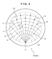
- the gas discharge ports 12 are arranged along multiple virtual lines L radially extending from the position of the gas inlet 11 (11a, 11b), or along multiple virtual concentric circles (circular arc) C centered at the gas inlet 11. That is, in the separator 8A, the gas discharge ports 12 are arranged at positions where each of the virtual lines L and each of the virtual concentric circles C cross with each other.
- the angle formed by the virtual lines L adjoining to each other is set to be constant, and the interval between the concentric circles C adjoining to each other is set to be constant.
- each of the hole diameters is set so as to make the gas discharge quantity of each of the gas discharge ports 12 constant.
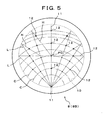
- the gas discharge ports 12 are provided at positions where each of the virtual lines L and each of the virtual concentric circles C cross with each other, similarly to the separator 8A shown in Figure 4 .
- a line segment passing through the gas inlet 11 and the center point P of the separator 8B is set as a first line segment 11
- a line segment perpendicularly intersecting the first line segment 11 at the center point P and having a length corresponding to the diameter of the hollow part 10 is set as a second line segment 12
- a multiple virtual lines L are radially drawn from the gas inlet 11 so as to pass through each of dividing points for dividing the second line segment 12 at an equal interval.
- the gas discharge ports 12 are also provided on auxiliary line segments H extending from the dividing points in the outer circumferential direction (the direction of points at which the outer circumference of the hollow part 10 intersects the virtual lines L).
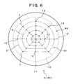
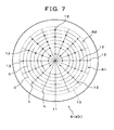
- the gas discharge ports 12 are respectively arranged along multiple virtual lines L radially extending from the center part of the separators 8C, 8D, or along the multiple virtual concentric circles C having their center in the center part of the separators 8C, 8D.
- the angle formed by virtual lines L adj oining to each other is set to be constant, and the interval between the virtual concentric circles C adjoining to each other is also set to be constant.
- the gas discharge ports 12 two kinds of large and small hole diameters are prepared for the gas discharge ports 12, so that the gas discharge ports having the small hole diameter are used for the gas discharge ports 12 existing in a region R1 on the side of the gas inlet 11 of the two regions into which the separator is divided by the second line segment 12 as a boundary, and for the gas discharge ports 12 on the second virtual line segment, while the gas discharge ports having the large hole diameter are used for the gas discharge ports 12 existing in the region R2 opposite to the gas inlet 11. That is, the hole diameter of the gas discharge port 12 is set so as to become large as the distance between the gas discharge port 12 and the gas inlet 11 increases.
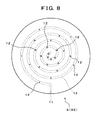
- the separator 8 instead of the hollow parts 10a, 10b, it is possible to use a separator which has an inner flow passage 13 for guiding reactive gas, and which is provided with gas discharge ports 12 along the inner flow passage 13, as shown in Figures 8 to 10 .
- the inner flow passage 13 is formed to be a spiral flow passage which has a starting point in the outer peripheral part, while in the separator 8F shown in Figure 9 , the inner flow passage 13 is formed in a zigzag manner from one end to the other end in the radial direction of the layer surface.
- the inner flow passage 13 is formed by multiple flow passages branched radially from the gas inlet 11 provided in the outer peripheral part.
- the hole diameter of the gas discharge port 12 is set to become large in stages from the upstream side toward the downstream side of the inner flow passage 13.
- the above described aluminum diffusion coating treatment is applied to the wall surface of the inner flow passage 13.
- the fuel gas introduced into the first hollow part 10a of the separator 8 from the manifold for fuel via the gas inlet 11a in the outer peripheral part of the separator is discharged like a shower toward the fuel electrode current collector 6 from a number of gas discharge ports 12a provided on approximately whole area on one layer surface 18a of the separator 8, while the oxidizer gas introduced into the second hollow part 10b of the separator 8 from the manifold for oxidizer via the gas inlet 11b in the outer peripheral part of the separator 8, is discharged like a shower toward the air electrode current collector 7 from a number of gas discharge ports 12b provided on approximately whole area on the other layer surface 18b of the separator 8.
- the fuel gas and the oxidizer gas are made to spread over the entire surfaces of the fuel electrode layer 3 and the air electrode layer 4 in uniform distribution, so that power generation reaction can be uniformly performed on the electrode-electrolyte interface.
- multiple gas discharge ports 12 are provided on approximately whole area of the layer surface of the separator 8, and the reactive gas (fuel gas, oxidizer gas) is arranged to be discharged like a shower from the gas discharge ports 12 toward the current collectors 6, 7 and each of the electrodes of the power generation cell 5 provided at the side next to the current collectors, as a result of which the gas concentration on the cell face can be made uniform.
- the reactive gas fuel gas, oxidizer gas
- the deviation in the electrode reaction can be suppressed, and the current density within the cell can be made uniform, with the result that the output power density per unit area can be increased and thereby the power generation efficiency of the power generation cell 5 as a whole can be remarkably improved, and that the temperature within the cell can be made uniform and thereby failure of the power generation cell 5 due to thermal stress can be prevented.
- the present embodiment is constituted such that multiple gas discharge ports 12 are provided on both of the layer surfaces 18a, 18b of the separator 8, respectively.
- gas concentration on the cell face can be made uniform and thereby the power generation efficiency can be improved, while the temperature distribution within the cell can also be made uniform and thereby failure of the power generation cell can be prevented. Further, deterioration caused by carburization can be suppressed, even in the case where a hydrocarbon compound, such as methane, is used as the fuel gas. Therefore, the durability of the separator can be improved, so that the separator and the solid oxide fuel cell can be used stably over a long period.
Landscapes
- Chemical & Material Sciences (AREA)
- Life Sciences & Earth Sciences (AREA)
- Engineering & Computer Science (AREA)
- Manufacturing & Machinery (AREA)
- Sustainable Development (AREA)
- Sustainable Energy (AREA)
- Chemical Kinetics & Catalysis (AREA)
- Electrochemistry (AREA)
- General Chemical & Material Sciences (AREA)
- Composite Materials (AREA)
- Fuel Cell (AREA)
Claims (6)
- Trennvorrichtung (8) für eine Brennstoffzelle, die in abwechselnder Laminierung mit einer Stromerzeugungszelle (5) angeordnet ist und auf einer Schichtoberfläche (18) derselben Gasablassöffnungen (12) zum Ablassen von reaktionsfähigem Gas aufweist, wobei die mehreren Gasablassöffnungen (12) auf ungefähr dem gesamten Bereich der Schichtoberfläche (18) vorgesehen sind und das reaktionsfähige Gas veranlasst wird, wie eine Dusche aus den Gasablassöffnungen (12) auf die Stromerzeugungszelle (5) zu abgelassen zu werden, weiter umfassend einen inneren Strömungsdurchgang (13) zum Leiten des reaktionsfähigen Gases, wobei die Gasablassöffnungen (12) entlang dem inneren Strömungsdurchgang (13) vorgesehen sind, und
wobei der Lochdurchmesser der Gasablassöffnungen (12) dazu eingestellt ist, von der stromaufwärtigen Seite zur stromabwärtigen Seite des inneren Strömungsdurchgangs (13) hin größer zu werden, und
die mehreren Gasablassöffnungen (12) auf beiden der Schichtoberflächen (18a, 18b) der Trennvorrichtung (8) vorgesehen sind. - Trennvorrichtung (8) für eine Brennstoffzelle nach Anspruch 1, wobei es sich bei dem inneren Strömungsdurchgang (13) um einen Spiral-Strömungsdurchgang mit einem Anfangspunkt in dem äußeren Randteil der Trennvorrichtung handelt.
- Trennvorrichtung (8) für eine Brennstoffzelle nach Anspruch 1, wobei der innere Strömungsdurchgang (13) in der Radialrichtung der Schichtoberfläche (18) in einem Zickzackzustand von einem Ende zum anderen Ende gebildet ist.
- Trennvorrichtung (8) für eine Brennstoffzelle nach Anspruch 1, wobei der innere Strömungsdurchgang (13) von mehreren Strömungsdurchgängen gebildet ist, die radial von einem Gaseinlass (11) in dem äußeren Randteil abzweigen.
- Trennvorrichtung (8) für eine Brennstoffzelle nach Anspruch 1, wobei die Wandoberfläche des inneren Strömungsdurchgangs (13) einer Aluminiumdiffusions-Beschichtungsbehandlung unterzogen wird, um Aluminium diffundiert und penetriert zu machen.
- Festoxid-Brennstoffzelle mit einem Brennstoffzellenstapel (1), der durch abwechselndes Laminieren von Stromerzeugungszellen (5) und Trennvorrichtungen (8) gebildet ist und der reaktionsfähiges Gas an jede der Stromerzeugungszellen (5) liefert, um eine Stromerzeugungsreaktion zu erzeugen,
wobei die Trennvorrichtung (8) nach Ansprüchen 1-5 definiert ist.
Applications Claiming Priority (6)
| Application Number | Priority Date | Filing Date | Title |
|---|---|---|---|
| JP2004009062 | 2004-01-16 | ||
| JP2004009061 | 2004-01-16 | ||
| JP2004269456 | 2004-09-16 | ||
| JP2004379099A JP5017777B2 (ja) | 2004-01-16 | 2004-12-28 | 燃料電池用セパレータ、セパレータの製造方法および固体酸化物形燃料電池 |
| JP2004379098A JP4934960B2 (ja) | 2004-01-16 | 2004-12-28 | 燃料電池用セパレータおよび固体酸化物形燃料電池 |
| PCT/JP2005/000295 WO2005069415A1 (ja) | 2004-01-16 | 2005-01-13 | 燃料電池用セパレータ、セパレータの製造方法および固体酸化物形燃料電池 |
Publications (3)
| Publication Number | Publication Date |
|---|---|
| EP1715539A1 EP1715539A1 (de) | 2006-10-25 |
| EP1715539A4 EP1715539A4 (de) | 2009-12-30 |
| EP1715539B1 true EP1715539B1 (de) | 2012-11-07 |
Family
ID=34799852
Family Applications (1)
| Application Number | Title | Priority Date | Filing Date |
|---|---|---|---|
| EP05703534A Expired - Lifetime EP1715539B1 (de) | 2004-01-16 | 2005-01-13 | Trennglied für eine brennstoffzelle, verfahren zur herstellung eines trennglieds und festoxid-brennstoffzelle |
Country Status (3)
| Country | Link |
|---|---|
| US (2) | US7776484B2 (de) |
| EP (1) | EP1715539B1 (de) |
| WO (1) | WO2005069415A1 (de) |
Families Citing this family (10)
| Publication number | Priority date | Publication date | Assignee | Title |
|---|---|---|---|---|
| JP5017857B2 (ja) * | 2005-12-16 | 2012-09-05 | 三菱マテリアル株式会社 | 燃料電池用のセパレータおよび固体酸化物形燃料電池 |
| JP2009200184A (ja) * | 2008-02-20 | 2009-09-03 | Tokyo Electron Ltd | プラズマ処理装置及びプラズマ処理装置のバッフル板 |
| KR100965693B1 (ko) * | 2008-06-03 | 2010-06-24 | 삼성에스디아이 주식회사 | 버스 바 및 이를 포함하는 이차전지 모듈 |
| US8883368B2 (en) * | 2008-11-21 | 2014-11-11 | Ballard Power Systems Inc. | Solid oxide fuel cell having rigidized support including nickel-based alloy |
| FR2957363B1 (fr) * | 2010-03-12 | 2012-04-20 | Commissariat Energie Atomique | Architecture d'electrolyseur a haute temperature, a production cible elevee par cellule d'electrolyse et taux de degradation des cellules limite |
| RS58010B1 (sr) | 2012-09-27 | 2019-02-28 | Childrens Medical Ct Corp | Jedinjenja za lečenje gojaznosti i postupci za njihovu upotrebu |
| WO2014063908A1 (en) * | 2012-10-23 | 2014-05-01 | Metacon Ab | Disc shaped fuel cell |
| CN110504469B (zh) * | 2018-05-16 | 2024-04-19 | 浙江暖阳科技有限公司 | 一种便于组装的集成式甲烷燃料电池 |
| US20210143447A1 (en) * | 2019-11-12 | 2021-05-13 | Bryan M. Blackburn | Stack configurations for solid oxide electrochemical cells |
| US20210143448A1 (en) * | 2019-11-12 | 2021-05-13 | Bryan M. Blackburn | Solid-state electrochemical devices having coated components |
Family Cites Families (10)
| Publication number | Priority date | Publication date | Assignee | Title |
|---|---|---|---|---|
| JPS5975575A (ja) * | 1982-10-22 | 1984-04-28 | Hitachi Ltd | 溶融炭酸塩型燃料電池 |
| US5957901A (en) * | 1997-10-14 | 1999-09-28 | Merit Medical Systems, Inc. | Catheter with improved spray pattern for pharmaco-mechanical thrombolysis therapy |
| JP4366872B2 (ja) * | 2000-03-13 | 2009-11-18 | トヨタ自動車株式会社 | 燃料電池用ガスセパレータおよび該燃料電池用セパレータの製造方法並びに燃料電池 |
| WO2001071842A2 (en) * | 2000-03-17 | 2001-09-27 | Allen Engineering Company, Inc. | Fuel cell stack assembly |
| WO2002054519A1 (en) * | 2000-12-28 | 2002-07-11 | Mitsubishi Materials Corporation | Fuel cell module and structure for gas supply to fuel cell |
| JP2002203588A (ja) * | 2000-12-28 | 2002-07-19 | Mitsubishi Materials Corp | 固体酸化物型燃料電池 |
| JP2002305005A (ja) * | 2001-04-03 | 2002-10-18 | Araco Corp | ガスセパレータおよびその製造方法 |
| AU2003211785A1 (en) * | 2002-03-04 | 2003-09-16 | Mitsubishi Materials Corporation | Solid oxide type fuel cell and separator |
| JP2004146345A (ja) * | 2002-08-28 | 2004-05-20 | Honda Motor Co Ltd | 燃料電池 |
| US20040265666A1 (en) * | 2003-06-27 | 2004-12-30 | Weil K. Scott | Solid oxide fuel cell frames and method of manufacture |
-
2005
- 2005-01-13 EP EP05703534A patent/EP1715539B1/de not_active Expired - Lifetime
- 2005-01-13 US US10/585,940 patent/US7776484B2/en not_active Expired - Fee Related
- 2005-01-13 WO PCT/JP2005/000295 patent/WO2005069415A1/ja not_active Ceased
-
2009
- 2009-12-23 US US12/654,555 patent/US20100104916A1/en not_active Abandoned
Also Published As
| Publication number | Publication date |
|---|---|
| US20070160892A1 (en) | 2007-07-12 |
| EP1715539A4 (de) | 2009-12-30 |
| US20100104916A1 (en) | 2010-04-29 |
| EP1715539A1 (de) | 2006-10-25 |
| WO2005069415A1 (ja) | 2005-07-28 |
| US7776484B2 (en) | 2010-08-17 |
Similar Documents
| Publication | Publication Date | Title |
|---|---|---|
| US20100104916A1 (en) | Separator for fuel cell, method for producing separator, and solid oxide fuel cell | |
| US5399442A (en) | Solid electrolyte fuel cell | |
| US11152627B2 (en) | Bipolar plate which has reactant gas channels with variable cross-sectional areas, fuel cell stack, and vehicle comprising such a fuel cell stack | |
| JP4574956B2 (ja) | 燃料電池 | |
| US8735020B2 (en) | Fuel cell | |
| JP2006032328A (ja) | 燃料電池 | |
| US6936366B2 (en) | Single chamber solid oxide fuel cell architecture for high temperature operation | |
| JP4300947B2 (ja) | 固体酸化物形燃料電池 | |
| JP3999934B2 (ja) | 固体電解質型燃料電池 | |
| US8507145B2 (en) | Fuel cell and method of producing the fuel cell | |
| JP4529393B2 (ja) | 固体酸化物形燃料電池 | |
| US8110318B2 (en) | Solid oxide fuel cell with reforming chamber integrated within separator plates | |
| JP2008053078A (ja) | 燃料電池及び燃料電池モジュール | |
| EP1535360B1 (de) | Separator für festoxidbrennstoffzellen mit internen reaktionsgaskanälen | |
| JP4934960B2 (ja) | 燃料電池用セパレータおよび固体酸化物形燃料電池 | |
| JP4963195B2 (ja) | セパレータおよび平板型固体酸化物形燃料電池 | |
| JP5017777B2 (ja) | 燃料電池用セパレータ、セパレータの製造方法および固体酸化物形燃料電池 | |
| JP4329345B2 (ja) | 内部改質式燃料電池 | |
| US8338047B2 (en) | Solid oxide fuel cell | |
| JP4706191B2 (ja) | 固体酸化物形燃料電池 | |
| JP2004055195A (ja) | 平板積層型の固体酸化物形燃料電池 | |
| JP4228895B2 (ja) | 固体酸化物型燃料電池 | |
| JP2006012548A (ja) | 固体酸化物形燃料電池 | |
| JP2005085524A (ja) | 固体酸化物型燃料電池 | |
| JP2006236597A (ja) | 燃料電池用セパレータおよび固体酸化物形燃料電池 |
Legal Events
| Date | Code | Title | Description |
|---|---|---|---|
| PUAI | Public reference made under article 153(3) epc to a published international application that has entered the european phase |
Free format text: ORIGINAL CODE: 0009012 |
|
| 17P | Request for examination filed |
Effective date: 20060720 |
|
| AK | Designated contracting states |
Kind code of ref document: A1 Designated state(s): AT BE BG CH CY CZ DE DK EE ES FI FR GB GR HU IE IS IT LI LT LU MC NL PL PT RO SE SI SK TR |
|
| DAX | Request for extension of the european patent (deleted) | ||
| A4 | Supplementary search report drawn up and despatched |
Effective date: 20091126 |
|
| 17Q | First examination report despatched |
Effective date: 20110126 |
|
| GRAP | Despatch of communication of intention to grant a patent |
Free format text: ORIGINAL CODE: EPIDOSNIGR1 |
|
| GRAS | Grant fee paid |
Free format text: ORIGINAL CODE: EPIDOSNIGR3 |
|
| GRAA | (expected) grant |
Free format text: ORIGINAL CODE: 0009210 |
|
| AK | Designated contracting states |
Kind code of ref document: B1 Designated state(s): AT BE BG CH CY CZ DE DK EE ES FI FR GB GR HU IE IS IT LI LT LU MC NL PL PT RO SE SI SK TR |
|
| REG | Reference to a national code |
Ref country code: GB Ref legal event code: FG4D |
|
| REG | Reference to a national code |
Ref country code: CH Ref legal event code: EP Ref country code: AT Ref legal event code: REF Ref document number: 583311 Country of ref document: AT Kind code of ref document: T Effective date: 20121115 |
|
| REG | Reference to a national code |
Ref country code: IE Ref legal event code: FG4D |
|
| REG | Reference to a national code |
Ref country code: DE Ref legal event code: R096 Ref document number: 602005036870 Country of ref document: DE Effective date: 20130103 |
|
| REG | Reference to a national code |
Ref country code: AT Ref legal event code: MK05 Ref document number: 583311 Country of ref document: AT Kind code of ref document: T Effective date: 20121107 |
|
| REG | Reference to a national code |
Ref country code: NL Ref legal event code: VDEP Effective date: 20121107 |
|
| REG | Reference to a national code |
Ref country code: LT Ref legal event code: MG4D |
|
| PG25 | Lapsed in a contracting state [announced via postgrant information from national office to epo] |
Ref country code: FI Free format text: LAPSE BECAUSE OF FAILURE TO SUBMIT A TRANSLATION OF THE DESCRIPTION OR TO PAY THE FEE WITHIN THE PRESCRIBED TIME-LIMIT Effective date: 20121107 Ref country code: IS Free format text: LAPSE BECAUSE OF FAILURE TO SUBMIT A TRANSLATION OF THE DESCRIPTION OR TO PAY THE FEE WITHIN THE PRESCRIBED TIME-LIMIT Effective date: 20130307 Ref country code: LT Free format text: LAPSE BECAUSE OF FAILURE TO SUBMIT A TRANSLATION OF THE DESCRIPTION OR TO PAY THE FEE WITHIN THE PRESCRIBED TIME-LIMIT Effective date: 20121107 Ref country code: NL Free format text: LAPSE BECAUSE OF FAILURE TO SUBMIT A TRANSLATION OF THE DESCRIPTION OR TO PAY THE FEE WITHIN THE PRESCRIBED TIME-LIMIT Effective date: 20121107 Ref country code: SE Free format text: LAPSE BECAUSE OF FAILURE TO SUBMIT A TRANSLATION OF THE DESCRIPTION OR TO PAY THE FEE WITHIN THE PRESCRIBED TIME-LIMIT Effective date: 20121107 |
|
| PG25 | Lapsed in a contracting state [announced via postgrant information from national office to epo] |
Ref country code: BE Free format text: LAPSE BECAUSE OF FAILURE TO SUBMIT A TRANSLATION OF THE DESCRIPTION OR TO PAY THE FEE WITHIN THE PRESCRIBED TIME-LIMIT Effective date: 20121107 Ref country code: PT Free format text: LAPSE BECAUSE OF FAILURE TO SUBMIT A TRANSLATION OF THE DESCRIPTION OR TO PAY THE FEE WITHIN THE PRESCRIBED TIME-LIMIT Effective date: 20130307 Ref country code: SI Free format text: LAPSE BECAUSE OF FAILURE TO SUBMIT A TRANSLATION OF THE DESCRIPTION OR TO PAY THE FEE WITHIN THE PRESCRIBED TIME-LIMIT Effective date: 20121107 Ref country code: GR Free format text: LAPSE BECAUSE OF FAILURE TO SUBMIT A TRANSLATION OF THE DESCRIPTION OR TO PAY THE FEE WITHIN THE PRESCRIBED TIME-LIMIT Effective date: 20130208 Ref country code: PL Free format text: LAPSE BECAUSE OF FAILURE TO SUBMIT A TRANSLATION OF THE DESCRIPTION OR TO PAY THE FEE WITHIN THE PRESCRIBED TIME-LIMIT Effective date: 20121107 |
|
| PG25 | Lapsed in a contracting state [announced via postgrant information from national office to epo] |
Ref country code: AT Free format text: LAPSE BECAUSE OF FAILURE TO SUBMIT A TRANSLATION OF THE DESCRIPTION OR TO PAY THE FEE WITHIN THE PRESCRIBED TIME-LIMIT Effective date: 20121107 |
|
| PG25 | Lapsed in a contracting state [announced via postgrant information from national office to epo] |
Ref country code: DK Free format text: LAPSE BECAUSE OF FAILURE TO SUBMIT A TRANSLATION OF THE DESCRIPTION OR TO PAY THE FEE WITHIN THE PRESCRIBED TIME-LIMIT Effective date: 20121107 Ref country code: EE Free format text: LAPSE BECAUSE OF FAILURE TO SUBMIT A TRANSLATION OF THE DESCRIPTION OR TO PAY THE FEE WITHIN THE PRESCRIBED TIME-LIMIT Effective date: 20121107 Ref country code: CY Free format text: LAPSE BECAUSE OF FAILURE TO SUBMIT A TRANSLATION OF THE DESCRIPTION OR TO PAY THE FEE WITHIN THE PRESCRIBED TIME-LIMIT Effective date: 20121107 Ref country code: CZ Free format text: LAPSE BECAUSE OF FAILURE TO SUBMIT A TRANSLATION OF THE DESCRIPTION OR TO PAY THE FEE WITHIN THE PRESCRIBED TIME-LIMIT Effective date: 20121107 Ref country code: BG Free format text: LAPSE BECAUSE OF FAILURE TO SUBMIT A TRANSLATION OF THE DESCRIPTION OR TO PAY THE FEE WITHIN THE PRESCRIBED TIME-LIMIT Effective date: 20130207 Ref country code: SK Free format text: LAPSE BECAUSE OF FAILURE TO SUBMIT A TRANSLATION OF THE DESCRIPTION OR TO PAY THE FEE WITHIN THE PRESCRIBED TIME-LIMIT Effective date: 20121107 |
|
| PG25 | Lapsed in a contracting state [announced via postgrant information from national office to epo] |
Ref country code: MC Free format text: LAPSE BECAUSE OF NON-PAYMENT OF DUE FEES Effective date: 20130131 Ref country code: RO Free format text: LAPSE BECAUSE OF FAILURE TO SUBMIT A TRANSLATION OF THE DESCRIPTION OR TO PAY THE FEE WITHIN THE PRESCRIBED TIME-LIMIT Effective date: 20121107 Ref country code: IT Free format text: LAPSE BECAUSE OF FAILURE TO SUBMIT A TRANSLATION OF THE DESCRIPTION OR TO PAY THE FEE WITHIN THE PRESCRIBED TIME-LIMIT Effective date: 20121107 |
|
| REG | Reference to a national code |
Ref country code: CH Ref legal event code: PL |
|
| PLBE | No opposition filed within time limit |
Free format text: ORIGINAL CODE: 0009261 |
|
| STAA | Information on the status of an ep patent application or granted ep patent |
Free format text: STATUS: NO OPPOSITION FILED WITHIN TIME LIMIT |
|
| 26N | No opposition filed |
Effective date: 20130808 |
|
| REG | Reference to a national code |
Ref country code: IE Ref legal event code: MM4A |
|
| PG25 | Lapsed in a contracting state [announced via postgrant information from national office to epo] |
Ref country code: ES Free format text: LAPSE BECAUSE OF FAILURE TO SUBMIT A TRANSLATION OF THE DESCRIPTION OR TO PAY THE FEE WITHIN THE PRESCRIBED TIME-LIMIT Effective date: 20130218 Ref country code: CH Free format text: LAPSE BECAUSE OF NON-PAYMENT OF DUE FEES Effective date: 20130131 Ref country code: LI Free format text: LAPSE BECAUSE OF NON-PAYMENT OF DUE FEES Effective date: 20130131 |
|
| REG | Reference to a national code |
Ref country code: DE Ref legal event code: R097 Ref document number: 602005036870 Country of ref document: DE Effective date: 20130808 |
|
| PG25 | Lapsed in a contracting state [announced via postgrant information from national office to epo] |
Ref country code: IE Free format text: LAPSE BECAUSE OF NON-PAYMENT OF DUE FEES Effective date: 20130113 |
|
| REG | Reference to a national code |
Ref country code: FR Ref legal event code: PLFP Year of fee payment: 11 |
|
| PGFP | Annual fee paid to national office [announced via postgrant information from national office to epo] |
Ref country code: DE Payment date: 20150106 Year of fee payment: 11 |
|
| REG | Reference to a national code |
Ref country code: DE Ref legal event code: R082 Ref document number: 602005036870 Country of ref document: DE Representative=s name: PATENTANWAELTE WEICKMANN & WEICKMANN, DE Ref country code: DE Ref legal event code: R082 Ref document number: 602005036870 Country of ref document: DE Representative=s name: WEICKMANN & WEICKMANN PATENTANWAELTE - RECHTSA, DE |
|
| PGFP | Annual fee paid to national office [announced via postgrant information from national office to epo] |
Ref country code: GB Payment date: 20150107 Year of fee payment: 11 Ref country code: FR Payment date: 20150108 Year of fee payment: 11 |
|
| PG25 | Lapsed in a contracting state [announced via postgrant information from national office to epo] |
Ref country code: TR Free format text: LAPSE BECAUSE OF FAILURE TO SUBMIT A TRANSLATION OF THE DESCRIPTION OR TO PAY THE FEE WITHIN THE PRESCRIBED TIME-LIMIT Effective date: 20121107 |
|
| PG25 | Lapsed in a contracting state [announced via postgrant information from national office to epo] |
Ref country code: LU Free format text: LAPSE BECAUSE OF NON-PAYMENT OF DUE FEES Effective date: 20130113 Ref country code: HU Free format text: LAPSE BECAUSE OF FAILURE TO SUBMIT A TRANSLATION OF THE DESCRIPTION OR TO PAY THE FEE WITHIN THE PRESCRIBED TIME-LIMIT; INVALID AB INITIO Effective date: 20050113 |
|
| REG | Reference to a national code |
Ref country code: DE Ref legal event code: R119 Ref document number: 602005036870 Country of ref document: DE |
|
| GBPC | Gb: european patent ceased through non-payment of renewal fee |
Effective date: 20160113 |
|
| REG | Reference to a national code |
Ref country code: FR Ref legal event code: ST Effective date: 20160930 |
|
| PG25 | Lapsed in a contracting state [announced via postgrant information from national office to epo] |
Ref country code: GB Free format text: LAPSE BECAUSE OF NON-PAYMENT OF DUE FEES Effective date: 20160113 Ref country code: DE Free format text: LAPSE BECAUSE OF NON-PAYMENT OF DUE FEES Effective date: 20160802 |
|
| PG25 | Lapsed in a contracting state [announced via postgrant information from national office to epo] |
Ref country code: FR Free format text: LAPSE BECAUSE OF NON-PAYMENT OF DUE FEES Effective date: 20160201 |