EP1715540B1 - Dispositif de génération d'énergie par pile à combustible - Google Patents
Dispositif de génération d'énergie par pile à combustible Download PDFInfo
- Publication number
- EP1715540B1 EP1715540B1 EP05703948.9A EP05703948A EP1715540B1 EP 1715540 B1 EP1715540 B1 EP 1715540B1 EP 05703948 A EP05703948 A EP 05703948A EP 1715540 B1 EP1715540 B1 EP 1715540B1
- Authority
- EP
- European Patent Office
- Prior art keywords
- channel
- cathode
- offgas
- oxygen
- fuel cell
- Prior art date
- Legal status (The legal status is an assumption and is not a legal conclusion. Google has not performed a legal analysis and makes no representation as to the accuracy of the status listed.)
- Expired - Lifetime
Links
- 239000000446 fuel Substances 0.000 title claims description 355
- 229910052760 oxygen Inorganic materials 0.000 claims description 291
- 239000001301 oxygen Substances 0.000 claims description 291
- QVGXLLKOCUKJST-UHFFFAOYSA-N atomic oxygen Chemical compound [O] QVGXLLKOCUKJST-UHFFFAOYSA-N 0.000 claims description 290
- 238000006057 reforming reaction Methods 0.000 claims description 234
- 239000007789 gas Substances 0.000 claims description 211
- 239000001257 hydrogen Substances 0.000 claims description 144
- 229910052739 hydrogen Inorganic materials 0.000 claims description 144
- UFHFLCQGNIYNRP-UHFFFAOYSA-N Hydrogen Chemical compound [H][H] UFHFLCQGNIYNRP-UHFFFAOYSA-N 0.000 claims description 136
- 239000003507 refrigerant Substances 0.000 claims description 128
- 230000001105 regulatory effect Effects 0.000 claims description 91
- 238000002407 reforming Methods 0.000 claims description 85
- 238000002156 mixing Methods 0.000 claims description 63
- 239000012528 membrane Substances 0.000 claims description 60
- 239000004020 conductor Substances 0.000 claims description 34
- 238000002485 combustion reaction Methods 0.000 claims description 31
- 229910052751 metal Inorganic materials 0.000 claims description 27
- 239000002184 metal Substances 0.000 claims description 27
- 230000005611 electricity Effects 0.000 claims description 24
- 239000003792 electrolyte Substances 0.000 claims description 22
- 238000000034 method Methods 0.000 claims description 11
- 238000001816 cooling Methods 0.000 claims description 5
- 238000010438 heat treatment Methods 0.000 claims description 5
- 239000012466 permeate Substances 0.000 claims description 5
- 229910010293 ceramic material Inorganic materials 0.000 claims description 4
- XLYOFNOQVPJJNP-UHFFFAOYSA-N water Substances O XLYOFNOQVPJJNP-UHFFFAOYSA-N 0.000 description 135
- 238000006243 chemical reaction Methods 0.000 description 44
- 229910052799 carbon Inorganic materials 0.000 description 19
- 238000007254 oxidation reaction Methods 0.000 description 14
- 229910052717 sulfur Inorganic materials 0.000 description 13
- 238000000629 steam reforming Methods 0.000 description 12
- 239000007787 solid Substances 0.000 description 11
- 238000007599 discharging Methods 0.000 description 10
- KDLHZDBZIXYQEI-UHFFFAOYSA-N Palladium Chemical compound [Pd] KDLHZDBZIXYQEI-UHFFFAOYSA-N 0.000 description 9
- 150000002431 hydrogen Chemical class 0.000 description 8
- 238000010248 power generation Methods 0.000 description 8
- UGFAIRIUMAVXCW-UHFFFAOYSA-N Carbon monoxide Chemical compound [O+]#[C-] UGFAIRIUMAVXCW-UHFFFAOYSA-N 0.000 description 7
- OKTJSMMVPCPJKN-UHFFFAOYSA-N Carbon Chemical compound [C] OKTJSMMVPCPJKN-UHFFFAOYSA-N 0.000 description 6
- LFQSCWFLJHTTHZ-UHFFFAOYSA-N Ethanol Chemical compound CCO LFQSCWFLJHTTHZ-UHFFFAOYSA-N 0.000 description 5
- 239000003054 catalyst Substances 0.000 description 5
- 239000000203 mixture Substances 0.000 description 5
- 229920005597 polymer membrane Polymers 0.000 description 5
- 238000009834 vaporization Methods 0.000 description 5
- 230000008016 vaporization Effects 0.000 description 5
- 239000004215 Carbon black (E152) Substances 0.000 description 4
- OAICVXFJPJFONN-UHFFFAOYSA-N Phosphorus Chemical compound [P] OAICVXFJPJFONN-UHFFFAOYSA-N 0.000 description 4
- 239000002253 acid Substances 0.000 description 4
- 230000008021 deposition Effects 0.000 description 4
- 230000002349 favourable effect Effects 0.000 description 4
- 229930195733 hydrocarbon Natural products 0.000 description 4
- 150000002430 hydrocarbons Chemical class 0.000 description 4
- VNWKTOKETHGBQD-UHFFFAOYSA-N methane Chemical compound C VNWKTOKETHGBQD-UHFFFAOYSA-N 0.000 description 4
- 230000003647 oxidation Effects 0.000 description 4
- 229910052763 palladium Inorganic materials 0.000 description 4
- 229910052698 phosphorus Inorganic materials 0.000 description 4
- 239000011574 phosphorus Substances 0.000 description 4
- 231100000572 poisoning Toxicity 0.000 description 4
- 230000000607 poisoning effect Effects 0.000 description 4
- 239000000126 substance Substances 0.000 description 4
- OKKJLVBELUTLKV-UHFFFAOYSA-N Methanol Chemical compound OC OKKJLVBELUTLKV-UHFFFAOYSA-N 0.000 description 3
- 230000006866 deterioration Effects 0.000 description 3
- 238000011084 recovery Methods 0.000 description 3
- CURLTUGMZLYLDI-UHFFFAOYSA-N Carbon dioxide Chemical compound O=C=O CURLTUGMZLYLDI-UHFFFAOYSA-N 0.000 description 2
- NBIIXXVUZAFLBC-UHFFFAOYSA-N Phosphoric acid Chemical compound OP(O)(O)=O NBIIXXVUZAFLBC-UHFFFAOYSA-N 0.000 description 2
- ATUOYWHBWRKTHZ-UHFFFAOYSA-N Propane Chemical compound CCC ATUOYWHBWRKTHZ-UHFFFAOYSA-N 0.000 description 2
- 239000000956 alloy Substances 0.000 description 2
- 229910045601 alloy Inorganic materials 0.000 description 2
- 239000000919 ceramic Substances 0.000 description 2
- 239000002737 fuel gas Substances 0.000 description 2
- -1 propane and butane Chemical compound 0.000 description 2
- 229910002761 BaCeO3 Inorganic materials 0.000 description 1
- OTMSDBZUPAUEDD-UHFFFAOYSA-N Ethane Chemical compound CC OTMSDBZUPAUEDD-UHFFFAOYSA-N 0.000 description 1
- 239000004721 Polyphenylene oxide Substances 0.000 description 1
- XUIMIQQOPSSXEZ-UHFFFAOYSA-N Silicon Chemical compound [Si] XUIMIQQOPSSXEZ-UHFFFAOYSA-N 0.000 description 1
- 229910003408 SrCeO3 Inorganic materials 0.000 description 1
- QRSFFHRCBYCWBS-UHFFFAOYSA-N [O].[O] Chemical compound [O].[O] QRSFFHRCBYCWBS-UHFFFAOYSA-N 0.000 description 1
- 229910000147 aluminium phosphate Inorganic materials 0.000 description 1
- 230000005540 biological transmission Effects 0.000 description 1
- 239000001273 butane Substances 0.000 description 1
- 239000001569 carbon dioxide Substances 0.000 description 1
- 229910002092 carbon dioxide Inorganic materials 0.000 description 1
- 229910017052 cobalt Inorganic materials 0.000 description 1
- 239000010941 cobalt Substances 0.000 description 1
- 238000004891 communication Methods 0.000 description 1
- 230000000694 effects Effects 0.000 description 1
- 239000011737 fluorine Substances 0.000 description 1
- 229910052731 fluorine Inorganic materials 0.000 description 1
- 125000001153 fluoro group Chemical group F* 0.000 description 1
- GPRLSGONYQIRFK-UHFFFAOYSA-N hydron Chemical compound [H+] GPRLSGONYQIRFK-UHFFFAOYSA-N 0.000 description 1
- 239000010416 ion conductor Substances 0.000 description 1
- 239000003915 liquefied petroleum gas Substances 0.000 description 1
- 239000000463 material Substances 0.000 description 1
- IJDNQMDRQITEOD-UHFFFAOYSA-N n-butane Chemical compound CCCC IJDNQMDRQITEOD-UHFFFAOYSA-N 0.000 description 1
- OFBQJSOFQDEBGM-UHFFFAOYSA-N n-pentane Natural products CCCCC OFBQJSOFQDEBGM-UHFFFAOYSA-N 0.000 description 1
- TVMXDCGIABBOFY-UHFFFAOYSA-N octane Chemical compound CCCCCCCC TVMXDCGIABBOFY-UHFFFAOYSA-N 0.000 description 1
- AHKZTVQIVOEVFO-UHFFFAOYSA-N oxide(2-) Chemical compound [O-2] AHKZTVQIVOEVFO-UHFFFAOYSA-N 0.000 description 1
- 230000035515 penetration Effects 0.000 description 1
- 229920000867 polyelectrolyte Polymers 0.000 description 1
- 229920000642 polymer Polymers 0.000 description 1
- 229920006380 polyphenylene oxide Polymers 0.000 description 1
- 238000001556 precipitation Methods 0.000 description 1
- 238000003825 pressing Methods 0.000 description 1
- 230000002265 prevention Effects 0.000 description 1
- 239000001294 propane Substances 0.000 description 1
- 239000002994 raw material Substances 0.000 description 1
- 229920006395 saturated elastomer Polymers 0.000 description 1
- 229910052710 silicon Inorganic materials 0.000 description 1
- 239000010703 silicon Substances 0.000 description 1
- HBMJWWWQQXIZIP-UHFFFAOYSA-N silicon carbide Chemical compound [Si+]#[C-] HBMJWWWQQXIZIP-UHFFFAOYSA-N 0.000 description 1
- 229910010271 silicon carbide Inorganic materials 0.000 description 1
- 230000007928 solubilization Effects 0.000 description 1
- 238000005063 solubilization Methods 0.000 description 1
- 238000001179 sorption measurement Methods 0.000 description 1
- LEONUFNNVUYDNQ-UHFFFAOYSA-N vanadium atom Chemical compound [V] LEONUFNNVUYDNQ-UHFFFAOYSA-N 0.000 description 1
- 229920002554 vinyl polymer Polymers 0.000 description 1
Images





Classifications
-
- H—ELECTRICITY
- H01—ELECTRIC ELEMENTS
- H01M—PROCESSES OR MEANS, e.g. BATTERIES, FOR THE DIRECT CONVERSION OF CHEMICAL ENERGY INTO ELECTRICAL ENERGY
- H01M8/00—Fuel cells; Manufacture thereof
- H01M8/04—Auxiliary arrangements, e.g. for control of pressure or for circulation of fluids
- H01M8/04082—Arrangements for control of reactant parameters, e.g. pressure or concentration
- H01M8/04089—Arrangements for control of reactant parameters, e.g. pressure or concentration of gaseous reactants
- H01M8/04097—Arrangements for control of reactant parameters, e.g. pressure or concentration of gaseous reactants with recycling of the reactants
-
- H—ELECTRICITY
- H01—ELECTRIC ELEMENTS
- H01M—PROCESSES OR MEANS, e.g. BATTERIES, FOR THE DIRECT CONVERSION OF CHEMICAL ENERGY INTO ELECTRICAL ENERGY
- H01M8/00—Fuel cells; Manufacture thereof
- H01M8/04—Auxiliary arrangements, e.g. for control of pressure or for circulation of fluids
- H01M8/04007—Auxiliary arrangements, e.g. for control of pressure or for circulation of fluids related to heat exchange
- H01M8/04014—Heat exchange using gaseous fluids; Heat exchange by combustion of reactants
- H01M8/04022—Heating by combustion
-
- H—ELECTRICITY
- H01—ELECTRIC ELEMENTS
- H01M—PROCESSES OR MEANS, e.g. BATTERIES, FOR THE DIRECT CONVERSION OF CHEMICAL ENERGY INTO ELECTRICAL ENERGY
- H01M8/00—Fuel cells; Manufacture thereof
- H01M8/06—Combination of fuel cells with means for production of reactants or for treatment of residues
- H01M8/0606—Combination of fuel cells with means for production of reactants or for treatment of residues with means for production of gaseous reactants
- H01M8/0612—Combination of fuel cells with means for production of reactants or for treatment of residues with means for production of gaseous reactants from carbon-containing material
-
- Y—GENERAL TAGGING OF NEW TECHNOLOGICAL DEVELOPMENTS; GENERAL TAGGING OF CROSS-SECTIONAL TECHNOLOGIES SPANNING OVER SEVERAL SECTIONS OF THE IPC; TECHNICAL SUBJECTS COVERED BY FORMER USPC CROSS-REFERENCE ART COLLECTIONS [XRACs] AND DIGESTS
- Y02—TECHNOLOGIES OR APPLICATIONS FOR MITIGATION OR ADAPTATION AGAINST CLIMATE CHANGE
- Y02E—REDUCTION OF GREENHOUSE GAS [GHG] EMISSIONS, RELATED TO ENERGY GENERATION, TRANSMISSION OR DISTRIBUTION
- Y02E60/00—Enabling technologies; Technologies with a potential or indirect contribution to GHG emissions mitigation
- Y02E60/30—Hydrogen technology
- Y02E60/50—Fuel cells
Definitions
- the present invention relates to a fuel cell system generating electricity by generating a hydrogen-containing reformed gas from a reforming fuel in a reformer and using the hydrogen in the hydrogen-containing reformed gas in a fuel cell.
- Fuel cell systems generating electricity by using a reforming fuel such as hydrocarbon or alcohol have a reformer generating a reformed gas containing hydrogen from the reforming fuel, and a hydrogen-separating membrane device separating high-purity hydrogen from the reformed gas, and a fuel cell generating electricity by converting the hydrogen into the proton state and allowing it to react with oxygen.
- the reformer generates the reformed gas, for example, in steam-reforming reaction of the reforming fuel with water and partial oxidation reaction of the reforming fuel with oxygen.
- the hydrogen-separating membrane device has a hydrogen-separating membrane for example of palladium, and the hydrogen-separating membrane has a property allowing permeation only of hydrogen.
- the fuel cell has an anode channel to which the hydrogen permeated through the hydrogen-separating membrane is supplied, a cathode channel to which air and others are supplied, and a proton conductor (electrolyte) placed between these channels.
- the cathode off gas discharged from the cathode channel contains water generated in reaction of the proton with oxygen, oxygen unconsumed in reaction with proton oxygen, and others.
- the cathode offgas is used in reactions in the reformer, in the fuel cell of JP 2003-151599 A (Patent Document 1).
- the anode offgas discharged from the anode channel also contains hydrogen that unpermeated through the proton conductor, water sent from the reformer, and others.
- the anode offgas is used in the reforming reaction in the reformer, in the fuel cell of JP 2001-223017 A (Patent Document 2).
- Examples of such fuel cells include solid polymer-membrane fuel cells using a solid polymer membrane as the proton conductor, phosphorus acid fuel cells using a phosphoric acid-impregnated silicon carbide as the proton conductor, and the like.
- the reaction in the reformer is preformed at a high temperature for example of 400°C or more for prevention of precipitation of carbon, but the operational temperature of the fuel cell is about 20 to 120°C in solid polymer-membrane fuel cells and about 120 to 210°C in phosphorus acid fuel cells because the proton conductor is used as it is impregnated with a solution.
- the heat of the reformed gas is transferred to the cathode offgas and the temperature of the reformed gas is lowered by heat exchange of the reformed gas generated in the reformer with the cathode offgas in a heat exchanger and the temperature of the hydrogen permeated through the hydrogen-separating membrane is also lowered in another heat exchanger, before supply of the gases to the fuel cell.
- the temperature of the hydrogen permeated through the hydrogen-separating membrane is lowered by passage through a condenser, and then it is supplied to the fuel cell.
- the temperature of the hydrogen to be supplied to the fuel cell is lowered deliberately, and it is not possible to use the heat of the cathode offgas discharged from the cathode channel of the fuel cell in reaction in the reformer.
- use of the heat exchanger, or the condenser, and the like leads to energy loss and also makes the structure of the fuel cell system more complicated.
- the proton conductor is used as it is impregnated with a solution in the solid polymer-membrane and phosphorus acid fuel cells.
- the water generated in reaction of the proton and oxygen in air in the cathode channel permeates through the proton conductor into the anode channel, by the back refusion due to the difference in water content between the anode and cathode channels.
- the water permeated into the anode channel is discharged from the anode channel by vaporization based on its saturated vapor pressure.
- Patent Document 3 which is considered as comprised in the state of the art pursuant to Art. 54(3) EPC, discloses a fuel cell system comprising a reformer and fuel cells that generate electricity by using hydrogen-containing reformed gas generated by the reformer. Part of the cathode offgas of the fuel cells is fed via a branched pipe into a mixer to be blended with only fuel gas and a separate supply of steam. The resulting gas mixture is led into the reformer to be subject to the reforming reaction.
- An object of the present invention which was made in view of the conventional problems, is to provide a fuel cell system simpler in structure that allows recovery of all water generated in the cathode channel and improvement in energy efficiency further by using the remaining oxygen and the high-temperature heat energy of the cathode offgas, and a method of generating electricity thereby.
- a first aspect of the present invention is a fuel cell system as defined in claim 1.
- the fuel cell system of the invention has a fuel cell having an electrolyte of a laminate of the hydrogen-separating metal layer and the proton conductor layer.
- a fuel cell having an electrolyte of a laminate of the hydrogen-separating metal layer and the proton conductor layer.
- the oxygen in the oxygen-containing gas supplied to the cathode channel reacts with the proton (also called H + or hydrogen ion) supplied from the anode channel to the cathode channel through the electrolyte to generate water.
- the fuel cell system can generate electricity in the reaction due to withdraw electricity from the anode and cathode electrodes formed on the electrolyte.
- the cathode offgas discharged from the cathode channel after reaction in the cathode channel contains oxygen unconsumed in the reaction (residual oxygen), water generated in the reaction (generated water), and the heat quantity by high-temperature operation of the fuel cell.
- the water generated in the cathode channel of the fuel cell is high-temperature steam, for example, at 300 to 600°C, and thus, the generated water is not impregnated into the proton conductor layer; and the generated water does not penetrate from the cathode channel to the anode channel, because the hydrogen-separating metal layer has a property allowing permeation only of hydrogen. For that reason, all of the generated water can be recovered from the cathode channel via the cathode offgas line.
- the present invention it is possible to obtain the water needed for reaction in the reforming reaction channel of the reformer from the cathode offgas containing water generated in electrical power generation of the fuel cell and to supply a sufficient amount of water to the reforming reaction channel.
- the fuel cell it is also possible to prevent vaporization of the components in the proton conductor layer and deposition thereof in the generated water in the cathode channel, because the proton conductor layer is used in the dry state. Accordingly, the generated water in the cathode offgas sent to the reformer is kept pure, eliminating, for example, the problem of the poisoning of reforming catalyst when it is placed in the reforming reaction channel of the reformer.
- the hydrogen-containing reformed gas is generated in reaction between the reforming fuel and the cathode offgas in the reformer in the present invention
- the temperature at which the hydrogen-containing reformed gas is generated in the reformer is significantly close to the operational temperature of the fuel cell in the invention.
- apparatuses such as heat exchanger and condenser that may be needed because of the difference in temperature, between the reformer and the fuel cell, which eliminates the energy loss by use of them and makes the structure of the fuel cell system simpler.
- solid oxide fuel cells In addition to the fuel cell system of the invention, there are known solid oxide fuel cells (SOFCs) operating at a high temperature of approximately 900 to 1,000°C.
- SOFCs solid oxide fuel cells
- the solid oxide fuel cells do not cause a problem of back refusion, i.e., penetration of water between the anode and cathode channels via the electrolyte.
- the solid oxide fuel cells generate electricity by making the oxygen supplied to the anode channel permeate through the oxide ionic conductor, thus converting the oxygen into the oxide ion state, permeate into the cathode channel, and react with hydrogen.
- the solid oxide fuel cells are completely different from the fuel cell according to the invention, which has an electrolyte of a laminate of the hydrogen-separating metal layer and the proton conductor layer. It is not possible to recover all generated water in the cathode offgas, which is generated in the anode channel during electrical power generation, in solid oxide fuel cells.
- a second aspect of the invention is a method of generating electricity in a fuel cell system as defined in claim 20.
- the method of generating electricity in a fuel cell system of the present invention is a method of generating electricity by using a fuel cell having an electrolyte of a laminate of the hydrogen-separating metal layer and the proton conductor layer similar to the invention above and operating the fuel cell at a high temperature, for example, of 300 to 600°C.
- the hydrogen-containing reformed gas can be generated in reaction of the remaining oxygen, a sufficient amount of the generated water, the cathode offgas having the high-temperature heat energy, and the reforming fuel in the reformer. According to the present invention, it is thus possible to generate electricity by making the most of the high-temperature heat energy of the cathode offgas and improve the energy efficiency of the fuel cell system additionally.
- All of the cathode offgas discharged from the cathode channel may be sent to the reformer via the cathode offgas line, or only part of it may be sent to the reformer, in the first and second inventions.
- the flow rate of the cathode offgas sent to the reformer is properly adjusted to the flow rate favorable for the reaction in the reformer.
- a steam reforming reaction generating hydrogen, carbon monooxide and others from a reforming fuel and water, and a partial oxidation reaction generating water, carbon monooxide, and others by combustion of part of the reforming fuel with oxygen occur in the reforming reaction channel of the reformer.
- a steam reforming reaction generating hydrogen, carbon monooxide and others from a reforming fuel and water
- a partial oxidation reaction generating water, carbon monooxide, and others by combustion of part of the reforming fuel with oxygen occur in the reforming reaction channel of the reformer.
- the reforming fuel may be, for example, a hydrocarbon fuel, an alcohol fuel, or the like.
- hydrocarbon fuels include fuel gases such as methane and ethane, liquefied petroleum gases such as propane and butane, and gasolines such as octane.
- the alcohol fuels include methanol, ethanol, and the like.
- the cathode offgas line feeds the cathode offgas into the reforming reactor channel not via a mixer mixing only the cathode offgas with the reforming fuel or a mixer mixing only the cathode offgas with steam.
- the first invention includes an embodiment of feeding the cathode offgas without a mixer into the reforming reactor channel, and an embodiment of connecting the cathode offgas line to a mixer mixing the cathode offgas with the reforming fuel or with the reforming fuel and steam, as well as, for example, with air, anode offgas, the reformer exhaust EGR gas, and others.
- the cathode offgas line feeding the cathode offgas not via a mixer into the reforming reactor channel, it is possible to make the structure of the fuel cell including pipings simpler and eliminate the energy loss due to use of such devices.
- the cathode offgas line is connected to a mixer mixing the cathode offgas with the reforming fuel, or with reforming fuel and steam, as well as, for example, with air, anode offgas, the reformer exhaust EGR gas, and others, it is possible to increase the efficiency of using hydrogen, heat and reforming fuel and the thermal efficiency of the fuel cell by ensuring the oxygen needed for partial oxidation, for example by supplying air from the air line via a mixer into the reformer or supplying the anode offgas and the exhaust EGR gas via the mixer, even when the amount of the oxygen in the cathode offgas is insufficient. It is thus possible to improve the reaction efficiency in the reformer, the efficiency of using the fuel and others, and the energy efficiency of the fuel cell system more.
- the reformer preferably has a heat exchange channel that is formed close to the reforming reaction channel and that heats the reforming reaction channel by combustion (Claim 2).
- an anode offgas line for feeding an anode offgas discharged from the anode channel to the heat exchange channel is preferably connected to the anode channel of the fuel cell (Claim 3).
- the anode offgas discharged from the anode channel contains the hydrogen discharged without permeation through the hydrogen-separating metal layer of the electrolyte, and the substances other than hydrogen contained in the hydrogen-containing reformed gas (in particular, combustible substances such as carbon monooxide and methane), and the heat quantity generated in high-temperature operation of the fuel cell.
- the hydrogen contained in the anode offgas, the combustible substances, and others for combustion in the heat exchange channel and also to carry out combustion by using the high-temperature heat energy of the anode offgas, by supplying the anode offgas from the anode channel via the anode offgas line to the heat exchange channel. It is also possible to generate the hydrogen-containing reformed gas in the reforming reaction channel, by using the high-temperature heat energy of the cathode offgas. Thus it is possible to improve the energy efficiency of the reformer and the energy efficiency of the fuel cell system.
- the fuel cell preferably has a refrigerant channel to which an oxygen-containing refrigerant gas for cooling the fuel cell is supplied (Claim 4).
- a refrigerant offgas line for feeding the refrigerant offgas discharged from the refrigerant channel into the heat exchange channel is preferably connected to the refrigerant channel of the fuel cell (Claim 5).
- the refrigerant offgas discharged from the refrigerant channel contains the oxygen contained in the oxygen-containing refrigerant gas and the heat obtained during passage through the fuel cell.
- cathode offgas discharged from the cathode channel can be fed via the cathode offgas line into the reforming reaction channel. It is possible to adjust the flow rate of the cathode offgas sent to the reforming reaction channel properly to the flow rate thereof needed for reaction in the reforming reaction channel.
- All or part of the anode offgas and the refrigerant offgas can also be fed via respectively the anode offgas line and the refrigerant offgas line into the heat exchange channel.
- the flow rate of the anode offgas or the flow rate of the refrigerant offgas sent to the heat exchange channel can be adjusted properly to the flow rate needed for combustion in the heat exchange channel.
- an exhaust three-way regulating valve is preferably installed on the cathode offgas line so that the fuel cell system can discharge part of the cathode offgas via the exhaust three-way regulating valve and feed a remaining part of the cathode offgas into the reforming reaction channel (Claim 6).
- the amount of the oxygen remaining in the cathode offgas unconsumed in reaction with proton also varies when the flow rate of the hydrogen-containing gas to the anode channel, the flow rate of the oxygen-containing gas to the cathode channel, or the like varies, and the ratio of the theoretical air quantity to the proton amount (cathode stoichiometry) in the cathode channel varies. It is possible then to reduce the flow rate of the cathode offgas sent to the reforming reaction channel by discharging part of the cathode offgas via the exhaust three-way regulating valve, especially when the amount of the remaining oxygen is more than the amount of oxygen needed for the reforming reaction channel. It is thus possible to keep the amount of the oxygen remaining in the cathode offgas sent to the reforming reaction channel in a suitable range.
- the theoretical air quantity used in calculating the cathode stoichiometry is a value of the oxygen-containing gas calculated as air.
- a supply three-way regulating valve may be installed on the cathode offgas line, so that the fuel cell system can feed part of the cathode offgas into the heat exchange channel via the supply three-way regulating valve, and a remaining part of the cathode offgas into the reforming reaction channel (Claim 7).
- a resupply three-way regulating valve is preferably installed on the cathode offgas line, so that the fuel cell system resupply part of the cathode offgas to the cathode channel via the resupply three-way regulating valve, and a remaining part of the cathode offgas into the reforming reaction channel (Claim 8).
- an oxygen-separating membrane is preferably installed on the cathode offgas line, so that the fuel cell system can discharge part of oxygen in the cathode offgas through the oxygen-separating membrane (Claim 9).
- an oxygen-separating membrane is preferably installed on the cathode offgas line so that the fuel cell system can resupply part of oxygen in the cathode offgas through the oxygen-separating membrane into the cathode channel (Claim 10).
- an oxygen-separating membrane is preferably installed on the cathode offgas line, so that the fuel cell system can feed part of oxygen in the cathode offgas through the oxygen-separating membrane into the heat exchange channel (Claim 11).
- an oxygen-separating membrane is preferably installed on the cathode offgas line, so that the fuel cell system can store part of oxygen in the cathode offgas through the oxygen-separating membrane in an oxygen buffer (Claim 12).
- the fuel cell system is preferably configured to mix part of the oxygen-containing refrigerant gas into the cathode offgas line (Claim 13).
- the fuel cell system may be configured to mix part of the refrigerant offgas into the cathode offgas line (Claim 14).
- the fuel cell system may be configured to mix air into the cathode offgas line (Claim 15).
- the fuel cell system may be configured to mix a reforming fuel into the cathode offgas line (Claim 16).
- the fuel cell system may be configured to mix part of the anode offgas into the cathode offgas line (Claim 17).
- the fuel cell system may be configured to mix part of the hydrogen-containing reformed gas into the cathode offgas line (Claim 18).
- the fuel cell system may be configured to mix hydrogen into the cathode offgas line (Claim 19).
- the cathode offgas line sends the cathode offgas into the reforming reactor channel directly, not via a mixer mixing the cathode offgas only with the reforming fuel or a mixer mixing the cathode offgas only with the reforming fuel and steam (Claim 20).
- the second invention includes an embodiment of sending the cathode offgas to the reforming reactor channel without a mixer, and an embodiment of the cathode offgas line being connected to a mixer mixing the cathode offgas with the reforming fuel or with the reforming fuel and steam, as well as, for example, with air, anode offgas, the reformer exhaust EGR gas, and others.
- the cathode offgas line sending the cathode offgas without a mixer into the reforming reactor channel, it is possible to make the structure of the fuel cell including pipings simpler and eliminate the energy loss due to use of such devices.
- the cathode offgas line is connected to a mixer mixing cathode offgas with the reforming fuel or with the reforming fuel and steam, as well as, for example, with air, anode offgas, the reformer exhaust EGR gas, and others, it is possible to increase the efficiencies of using the hydrogen, heat and reforming fuel and the thermal efficiency of the fuel cell by providing the oxygen needed for partial oxidation, for example, by supplying air through the air line via the mixer into the reformer or the anode offgas and the exhaust EGR gas via the mixer, even when the amount of the oxygen in the cathode offgas is insufficient. Accordingly, it is possible to improve the reaction efficiency in the reformer, the efficiency of using the fuel and others, and the energy efficiency of the fuel cell system further more.
- the reformer has a heat exchange channel formed close to the reforming reaction channel that heats the reforming reaction channel by combustion;
- the fuel cell has a refrigerant channel for feeding an oxygen-containing refrigerant gas for cooling the fuel cell; and the reforming reaction channel is heated by feeding the anode offgas discharged from the anode channel and the refrigerant offgas discharged from the refrigerant channel into the heat exchange channel, and combusting the anode offgas with the refrigerant offgas in the heat exchange channel (Claim 21).
- Examples 1 to 4 represent background art that is useful for understanding the invention
- Example 5 is an embodiment of the invention.
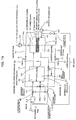
- the fuel cell system 1 in the present Example has a reformer 2 generating a hydrogen-containing reformed gas Ga containing hydrogen from a reforming fuel F of hydrocarbon fuel and a fuel cell 3 generating electricity by using the hydrogen-containing reformed gas Ga generated in the reformer 2.
- the reformer 2 has a reforming reaction channel 21 generating the hydrogen-containing reformed gas Ga from the reforming fuel F and a heat exchange channel 22 placed close to the reforming reaction channel 21 and heating the reforming reaction channel 21 by combustion.
- the fuel cell 3 has an anode channel 32 to which the hydrogen-containing reformed gas Ga is supplied from the reforming reaction channel 21, a cathode channel 33 to which an oxygen-containing gas Gc is supplied, an electrolyte 31 installed between the cathode channel 33 and the anode channel 32, and a refrigerant channel 34 to which an oxygen-containing refrigerant gas Gr for cooling the fuel cell 3 is supplied.
- the electrolyte 31 is a laminate of a hydrogen-separating metal layer (hydrogen-permeating metal layer) 311 allowing permeation of the hydrogen in the hydrogen-containing reformed gas Ga supplied to the anode channel 32 and a proton conductor layer 312, which is made of a ceramics material, converting the hydrogen permeating the hydrogen-separating metal layer 311 into the proton state and thus permeating it into to the cathode channel 33.
- a hydrogen-separating metal layer (hydrogen-permeating metal layer) 311 allowing permeation of the hydrogen in the hydrogen-containing reformed gas Ga supplied to the anode channel 32 and a proton conductor layer 312, which is made of a ceramics material, converting the hydrogen permeating the hydrogen-separating metal layer 311 into the proton state and thus permeating it into to the cathode channel 33.
- the fuel cell system 1 has a cathode offgas line 46 for feeding the cathode offgas Oc discharged from the cathode channel 33 into the reforming reaction channel 21 of the reformer 2, an anode offgas line 45 for feeding the anode offgas Oa discharged from the anode channel 32 to the heat exchange channel 22, and a refrigerant offgas line 47 for feeding the refrigerant offgas Or discharged from the refrigerant channel 34 to the heat exchange channel 22.
- a cathode offgas line 46 for feeding the cathode offgas Oc discharged from the cathode channel 33 into the reforming reaction channel 21 of the reformer 2
- an anode offgas line 45 for feeding the anode offgas Oa discharged from the anode channel 32 to the heat exchange channel 22
- a refrigerant offgas line 47 for feeding the refrigerant offgas Or discharged from the refrigerant channel 34 to the heat exchange channel 22.
- the reformer 2 is configured to generate the hydrogen-containing reformed gas Ga in reaction between the reforming fuel F and the cathode offgas Oc in the reforming reaction channel 21.
- the reformer 2 is also configured to generate the heat for heating by combustion of the anode offgas Oa and the refrigerant offgas Or in the heat exchange channel 22.
- the hydrogen-separating metal layer 311 in the present Example is a laminated metal of palladium (Pd) and vanadium (V).
- the hydrogen-separating metal layer 311 may be made only of palladium or of the alloy containing the same.
- the hydrogen-separating metal layer 311 has a hydrogen-permeating potential (hydrogen-separating potential) of equivalent to more than 10 A/cm ⁇ 2> as electric current density under an anode gas-feeding condition of 3 atmospheric pressures.
- the electric resistance of the hydrogen-separating metal layer 311 is made as small as negligible.
- the proton conductor layer 312 in the present Example is made of a ceramic perovskite oxide.
- the electric resistance of the proton conductor layer 312 is as small as that of solid polyelectrolyte membranes.
- the perovskite oxides include BaCeO3 -based and SrCeO3 -based oxides.
- the electrolyte 31 has an anode electrode 321 (anode) formed on the anode channel 32-sided surface of the proton conductor 312 and a cathode electrode 331 (cathode) formed on the cathode channel 33-sided surface of the proton conductor layer 312.
- a cell output cable 36 for outputting the power from the fuel cell 3 is connected between the anode electrode 321 and the cathode electrode 331.
- the anode electrode 321 in the proton conductor layer 312 of the present Example is made of palladium, which also constitutes the hydrogen-separating metal layer 311.
- the cathode electrode 331 in the proton conductor layer 312 of the present Example is made of a Pt-based electrode catalyst.
- the anode electrode 321 may be made of a Pt-based electrode catalyst.
- a cathode offgas three-way regulating valve 61as a three-way exhaust-gas regulating valve dividing the cathode offgas Oc flowing therein into two streams is formed on the cathode offgas line 46.
- the fuel cell system 1 is configured to discharge part of the cathode offgas Oc flowing in the cathode offgas line 46 and feed the other offgas into the reforming reaction channel 21 of the reformer 2 via the cathode offgas three-way regulating valve 61.
- the cathode offgas three-way regulating valve 61 can adjust the distribution ratio, i.e., the ratio of the flow rate of the cathode offgas Oc discharged to the flow rate of the cathode offgas Oc fed into the reforming reaction channel 21. It can also adjust the flow rated of cathode offgas Oc fed from the cathode offgas line 46 into the reforming reaction channel 21 of the reformer 2 with the cathode offgas three-way regulating valve 61.
- each of the three-way regulating valves used in the present Example is a branching valve having an inlet port introducing a gas, an outlet port discharging the gas and a relief port.
- the branching valve in the present Example can adjust the distribution ratio of the flow rates of the gasses respectively passing through the outlet port and the relief port.
- Three-way regulating valves described below are also the same.
- the cathode stoichiometry intentionally, by changing the flow rate of the hydrogen-containing reformed gas Ga into the anode channel 32, the flow rate of the oxygen-containing gas Gc into the cathode channel 33, or the like. It is then possible to adjust the ratio of the amount of water (water content) generated by the reaction between proton and oxygen in the cathode offgas Oc to the amount of the remaining oxygen. Even at the time, it is possible to keep the amount of oxygen remaining in the cathode offgas Oc sent to the reforming reaction channel 21 in a desirable range, by discharging part of the cathode offgas Oc via the cathode offgas three-way regulating valve 61.
- an anode offgas three-way regulating valve 51 for branching the anode offgas Oa flowing therein into two streams is formed on the anode offgas line 45 in the present Example.
- the fuel cell system 1 is configured to discharge part of the anode offgas Oa flowing in the anode offgas line 45 and feed the other offgas into the heat exchange channel 22 of the reformer 2 via the anode offgas three-way regulating valve 51.
- the anode offgas three-way regulating valve 51 can also adjust the distribution ratio of the flow rate of the discharged anode offgas Oa to the flow rate of the anode offgas Oa sent to the heat exchange channel 22. It is possible to adjust the flow rate of the anode offgas Oa sent from the anode offgas line 45 to the heat exchange channel 22 of the reformer 2 with the anode offgas three-way regulating valve 51.
- a refrigerant-offgas three-way regulating valve 71 for branching the refrigerant offgas flowing therein into two streams is placed on the refrigerant offgas line 47 in the present Example.
- the fuel cell system 1 is configured to discharge part of the refrigerant offgas Or flowing in the refrigerant offgas line 47 and feed the other offgas into the heat exchange channel 22 of the reformer 2 via the refrigerant-offgas three-way regulating valve 71.
- the refrigerant-offgas three-way regulating valve 71 can also adjust the distribution ratio of the flow rate of the refrigerant offgas Or discharged to the flow rate of the refrigerant offgas Or sent to the heat exchange channel 22.
- the fuel cell system 1 has a fuel feed line 41 for feeding the reforming fuel F into the reforming reaction channel 21 of the reformer 2.
- the cathode offgas line 46 is connected to the fuel feed line 41, and a reaction-channel mixing valve 881 for mixing the cathode offgas flowing in the cathode offgas line 46 with the reforming fuel F flowing in the fuel feed line 41 is formed in the connection portion. And, the mixed gas of reforming fuel F and cathode offgas Oc is fed to the reforming reaction channel 21 in the reformer 2.
- the cathode offgas line 46 may be connected directly to the reforming reaction channel 21, and the cathode offgas Oc and the reforming fuel F may be mixed in the reforming reaction channel 21.
- a steam reforming reaction occurs between the reforming fuel F and the water contained in the cathode offgas Oc (high-temperature steam), generating hydrogen, carbon monooxide, and others.
- a partial oxidation reaction also occurs by the reforming fuel F and the oxygen contained in the cathode offgas Oc in the reforming reaction channel 21, generating water, carbon monooxide, carbon dioxide, and others.
- the hydrogen-containing reformed gas Ga containing hydrogen, water, and others is generated in the steam reforming and partial oxidation reactions.
- the steam reforming reaction is an endothermic reaction, while the partial oxidation reaction is an exothermic reaction; and thus, it is possible to reduce the temperature drop of the reforming reaction channel 21 by the partial oxidation reaction.
- the anode offgas line 45 and the refrigerant offgas line 47 are connected to a gas mixing line for heating 451 communicating with the heat exchange channel 22 of the reformer 2.
- a heating-channel mixing valve 882 for mixing the anode offgas Oa flowing in the anode offgas line 45 and the refrigerant offgas Or flowing in the refrigerant offgas line 47 is installed in the connection portion.
- the mixed gas of the anode offgas Oa and the refrigerant offgas Or is fed to the heat exchange channel 22 of the reformer 2.
- the anode offgas line 45 and refrigerant offgas line 47 may respectively connected directly to the heat exchange channel 22, and in the anode offgas Oa and the refrigerant offgas Or may be mixed in the heat exchange channel 22.
- a combustion reaction between the hydrogen contained in the anode offgas Oa and the oxygen contained in the refrigerant offgas Or proceeds in the heat exchange channel 22, generating water and others.
- the temperature in the reforming reaction channel 21 high, by the combustion reaction in the heat exchange channel 22 and transmission of the heat from the heat exchange channel 22 to the reforming reaction channel 21.
- the temperature of the hydrogen-containing reformed gas Ga generated in the reformer 2 is kept in a certain temperature range, by balancing the quantity of the heat generated by the steam reforming and partial oxidation reactions in the reforming reaction channel 21 practically with the quantity of the heat generated by the combustion reaction in the heat exchange channel 22.
- the combustion offgas after combustion reaction in the heat exchange channel 22 is discharged out of the fuel cell system 1 through an exhaust line 49 connected to the outlet of the heat exchange channel 22.
- the reforming reaction channel 21 in the reformer 2 and the anode channel 32 in the fuel cell 3 are connected to each other, via a reformed-gas feed line 42 in which the hydrogen-containing reformed gas Ga generated in the reforming reaction channel 21 is flowing.
- the cathode channel 33 in the fuel cell 3 is connected to an oxygen-containing gas feed line 43 feeding an oxygen-containing gas Gc to the cathode channel 33.
- the oxygen-containing gas Gc is air
- an oxygen-containing gas pressurizer 60 feeding air, the oxygen-containing gas Gc, under pressure is installed on the oxygen-containing gas feed line 43.
- the oxygen-containing gas pressurizer 60 is a pump 60 in the present Example.
- the oxygen-containing gas pressurizer 60 may be a fan, compressor, ejector, or the like.
- oxygen may be used instead of air as the oxygen-containing gas Gc.
- a refrigerant gas feed line 44 for supplying an oxygen-containing refrigerant gas Gr into the refrigerant channel 34 is connected to the refrigerant channel 34 of the fuel cell 3.
- the oxygen-containing refrigerant gas Gr in the present Example is air
- a refrigerant gas pressurizer 70 for applying pressure to the oxygen-containing refrigerant gas Gr air and feeding it is installed on the refrigerant gas feed line 44. It is possible to keep the temperature in the fuel cell 3 in a suitable temperature range, by adjusting the feed rate of the oxygen-containing refrigerant gas Gr to the refrigerant channel 34 of fuel cell 3 with the refrigerant gas pressurizer 70.
- the refrigerant gas pressurizer 70 in the present Example is a pump 70.
- the refrigerant gas pressurizer 70 may be a fan, compressor, ejector, or the like.
- the fuel cell system 1 is configured to supply the hydrogen-containing reformed gas Ga directly from the reforming reaction channel 21 of the reformer 2 to the anode channel 32 of the fuel cell 3 without a heat exchanger, condenser, or the like.
- the fuel cell system 1 is configured to supply the cathode offgas Oc from cathode channel 33 of fuel cell 3 to the reforming reaction channel 21 in the reformer 2 directly without a heat exchanger or the like.
- One reforming reaction channel 21 and one heat exchange channel 22 are formed in the reformer 2 shown in Figure 1 .
- the reformer 2 may have respectively multiple reforming reaction channels 21 and heat exchange channels 22 that are installed alternately.
- the fuel cell 3 shown Figures 1 or 2 has an anode channel 32, a cathode channel 33 and a refrigerant channel 34.
- the fuel cell 3 may have respectively multiple anode channels 32, cathode channels 33 and refrigerant channels 34 that are installed alternately.
- the hydrogen-containing reformed gas Ga is generated in reaction of the reforming fuel F fed through the fuel feed line 41 with the cathode offgas Oc fed through the cathode offgas line 46 in the reforming reaction channel 21 the reformer 2.
- heat is generated in reaction of the anode offgas Oa fed through the anode offgas line 45 with the refrigerant offgas Or fed through the refrigerant offgas line 47, and the heat exchange channel 22 heats the reforming reaction channel 21.
- the temperature of the hydrogen-containing reformed gas Ga generated in the reformer 2 may be 300 to 600°C, but is more preferably 400 to 500°C. In such a case, it is possible to keep the temperature of the hydrogen-separating metal layer 311 in the electrolyte 31 of fuel cell 3 in the temperature range most suitable for showing its favorable hydrogen-permeating potential, and prevent, for example, deterioration of the hydrogen-separating metal layer 311 easily.
- the hydrogen-containing reformed gas Ga generated in the reforming reaction channel 21 of the reformer 2 is supplied, into the anode channel 32 of the fuel cell 3. Most of the hydrogen in the hydrogen-containing reformed gas Ga supplied to the anode channel 32 penetrates through the hydrogen-separating metal layer 311 of the electrolyte 31 and reaches the proton conductor layer 312 of the electrolyte 31. The hydrogen penetrates through proton conductor layer 312 in the proton state.
- the cathode channel 33 water is generated in reaction of the proton with oxygen in the oxygen-containing gas Gc supplied from the oxygen-containing gas feed line 43.
- the reaction in the fuel cell 3 is carried out at a high temperature of 300 to 600°C and the water generated becomes high-temperature steam.
- the fuel cell system 1 generates electricity by withdrawing electricity from the anode electrode 321 and the cathode electrode 331 of electrolyte 31 into the cell output cable 36 during the reaction.
- the fuel cell system 1 in the present Example has a fuel cell 3 having an electrolyte 31 of a laminate of the hydrogen-separating metal layer 311 and the proton conductor layer 312. It is possible to operate the fuel cell 3 at a high temperature, for example of 300 to 600°C in the fuel cell system 1 in the present Example, because the proton conductor layer 312 is made of a ceramic material and can be used without being impregnated with water. It is thus possible to supply the hydrogen-containing reformed gas Ga directly from the reformer 2 to the fuel cell 3.
- the cathode offgas Oc discharged from the cathode channel 33 after reaction in the cathode channel 33 has oxygen unconsumed in the reaction (residual oxygen), water generated in the reaction (generated water), and heat due to the high-temperature operation of fuel cell 3.
- the water generated in the cathode channel 33 of the fuel cell 3 is heated to a high-temperature steam, for example, at 300 to 600°C, and the generated water does not moisten the proton conductor layer 312 and does not penetrate from the cathode channel 33 to the anode channel 32, because the hydrogen-separating metal layer 311 allows only permeation of hydrogen.
- a high-temperature steam for example, at 300 to 600°C
- the fuel cell system 1 it is possible to use not only the residual oxygen and a sufficient amount of generated water contained in the cathode offgas Oc but also the high-temperature heat energy of the cathode offgas Oc in the reforming reaction channel 21, when the hydrogen-containing reformed gas Ga is generated in reaction of the reforming fuel F and the cathode offgas Oc in the reforming reaction channel 21 of the reformer 2. It is thus possible to generate the hydrogen-containing reformed gas Ga in reaction of the reforming fuel F with the cathode offgas Oc having the high-temperature heat energy in the reforming reaction channel 21 and to improve the energy efficiency of the reforming reaction channel 21.
- the anode offgas Oa discharged from the anode channel 32 has the hydrogen discharged unpermeated through the hydrogen-separating metal layer 311 of the electrolyte 31, the substances other than hydrogen contained in the hydrogen-containing reformed gas Ga, and the heat quantity of fuel cell 3 under high-temperature operation.
- the refrigerant offgas Or discharged from the refrigerant channel 34 has the oxygen contained in the oxygen-containing refrigerant gas Gr and the heat energy generated in the fuel cell 3.
- anode offgas Oa is supplied from the anode channel 32 via the anode offgas line 45 to the heat exchange channel 22 and the refrigerant offgas Or from the refrigerant channel 34 via the refrigerant offgas line 47 to the heat exchange channel 22, it is possible to combust the hydrogen contained in the anode offgas Oa with the oxygen contained in the refrigerant offgas Or and also to carry out the combustion by using the high-temperature heat energies respectively of the anode offgas and the refrigerant offgas Or, in the heat exchange channel 22. Thus, it is possible to improve the energy efficiency in the heat exchange channel 22.
- the fuel cell system 1 of the present Example it is also possible to make the temperature of the hydrogen-containing reformed gas Ga generated in the reformer 2 close to the operational temperature of the fuel cell 3, as described above. Consequently in the present Example, there is no need for installing devices needed when there is a difference in temperature between the reformer 2 and the fuel cell 3 such as heat exchanger, condenser, and the like. It is thus possible to eliminate the energy loss due to use of such additional devices and make the structure of the fuel cell system 1 simpler.
- the fuel cell system 1 in the present Example allows simplification of its structure, recovery of all water generated in the cathode channel 33, and improvement in the energy efficiency of the fuel cell system 1, by using the high-temperature heat energies respectively of the cathode offgas Oc, anode offgas Oa and refrigerant offgas Or.
- water and oxygen may be fed directly into the reforming reaction channel 21 in the reformer 2 and a fuel and oxygen (air, etc.) may be fed directly to the heat exchange channel 22 of the reformer 2 during startup of the fuel cell system 1.
- the water and oxygen needed for the reforming reaction channel 21 can be supplied only from the cathode offgas Oc, and the fuel hydrogen and oxygen needed for the heat exchange channel 22 can be supplied only from the anode offgas Oa and the refrigerant offgas Or.
- the hydrogen-separating metal layer 311 is almost free from the poisoning by carbon monooxide or the like, when the fuel cell 3 in the present Example is operated at high temperature, for example, of 300 to 600°C. Accordingly, it is possible to supply hydrogen as well as the hydrogen-containing reformed gas Ga containing carbon monooxide and others directly into the anode channel 32 of fuel cell 3 during the high-temperature operation.
- part of the cathode offgas Oc unconsumed in the reforming reaction channel 21 in the reformer 2 is discharged out of the fuel cell system 1 in the present Example.
- part of the cathode offgas Oc unconsumed in the reforming reaction channel 21 can be used in other units other than the reforming reaction channel 21 in the fuel cell system 1, for example, as follows:
- the fuel cell system 1 supplies part of the cathode offgas Oc flowing in the cathode offgas line 46 via supply three-way regulating valve 611 to the heat exchange channel 22 of the reformer 2 and the other offgas to the reforming reaction channel 21, as shown in Figure 3 .
- the relief port of the supply three-way regulating valve 611 placed on the cathode offgas line 46 is connected to the refrigerant offgas line 47 via a cathode offgas mixing line 48C, and a cathode offgas-refrigerant offgas mixing valve 88C is installed in the connection portion. And, part of the cathode offgas Oc flowing in the cathode offgas line 46 is mixed with the refrigerant offgas Or flowing in the refrigerant offgas line 47.
- part of the cathode offgas Oc not needed for the reforming reaction channel 21 can be used for combustion in the heat exchange channel 22. It is thus possible to improve the energy efficiency of the fuel cell system 1.
- the cathode offgas three-way regulating valve 61 may be place on the cathode offgas line 46, and it is also possible to reduce the flow rate of the cathode offgas Oc sent to the reforming reaction channel 21 with the cathode offgas three-way regulating valve 61.
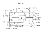
- the fuel cell system 1 resupplies part of the cathode offgas Oc flowing in the cathode offgas line 46 to the cathode channel 33 via a resupply three-way regulating valve 612 and the other offgas to the reforming reaction channel 21, as shown in Figure 4 .
- the relief port of the resupply three-way regulating valve 612 placed on the cathode offgas line 46 is connected to the oxygen-containing gas feed line 43 via a cathode offgas mixing line 48D, and a cathode offgas-oxygen-containing gas mixing valve 88D is installed in the connection portion.
- Part of the cathode offgas Oc flowing in the cathode offgas line 46 can be mixed with the oxygen-containing gas Gc flowing in the oxygen-containing gas feed line 43.
- the cathode offgas three-way regulating valve 61 may be installed on cathode offgas line 46 also in such a case. It is possible to determine the amount of water supplied to the reforming reaction channel 21 by adjusting the flow rate with the cathode offgas three-way regulating valve 61 and the amount of oxygen supplied to the reforming reaction channel 21 by adjusting the re-feed rate to the cathode channel 33 with the resupply three-way regulating valve 612. In this way, it is possible to control the amounts of the water and oxygen sent to the reforming reaction channel 21 and the ratio thereof properly.
- the ratio S/C of the mole amount of the water (S) in the cathode offgas Oc to the mole amount of the carbon (C) in the reforming fuel F is, for example, 1 to 3 in the reforming reaction channel 21 of the reformer 2.
- the ratio O/C of the mole amount of the oxygen (O) in the cathode offgas Oc to the mole amount of the carbon (C) in the reforming fuel F is, for example, 0 to 1.0 in the reforming reaction channel 21 of the reformer 2.
- the increase in the flow rate of the hydrogen-containing reformed gas Ga results in use of the reforming fuel F in a greater amount, and thus, drop in energy efficiency.
- a greater amount of water is demanded for the steam reforming reaction, because of the increase in amount of the reforming fuel F.
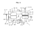
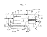
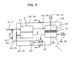
- the present shown in Figures 5 to 8 is a variation in which the O/C ratio (oxygen (O) to carbon (C) by mole) and the S/C ratio (water (S) to carbon (C) by mole) in the reforming reaction channel 21 of the reformer 2 are adjusted by installing an oxygen-separating membrane 81 on the cathode offgas line 46 for reducing the oxygen concentration in the cathode offgas Oc.
- the oxygen-separating membrane 81 is formed on the cathode offgas line 46 inside the oxygen-separating membrane device 80.
- the oxygen-separating membrane device 80 has an oxygen-separating membrane 81 allowing permeation of the oxygen in the cathode offgas Oc and two channels 811 and 812 separated by the oxygen-separating membrane 81.
- the two channels 811 and 812 are respectively an offgas channel 811 to which the cathode offgas Oc discharged from the cathode channel 33 is fed and an oxygen permeation channel 812 through which oxygen permeated through the oxygen-separating membrane 81 is flowing.
- the oxygen-separating membrane 81 is made, for example, of a silicon membrane, a vinyl aromatic amine polymer, meso-tetrakisporphinato-cobalt, polyphenylene oxide, or the like.
- a cathode offgas three-way regulating valve 61 is installed on the cathode offgas line 46 in the present Example.
- the fuel cell system 1 is configured to discharge the oxygen permeated through the oxygen-separating membrane 81 out of the fuel cell system 1. It is thus possible to reduce the oxygen amount in the cathode offgas Oc (the remaining oxygen amount) and keep the oxygen amount in the cathode offgas Oc sent to the reforming reaction channel 21 in a desirable range.
- oxygen permeated through the oxygen-separating membrane 81 placed on the cathode offgas line 46 may be used in units other than the reforming reaction channel 21 in the fuel cell system 1, as described below.
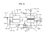
- the fuel cell system 1 may be configured to resupply the oxygen permeated through the oxygen-separating membrane 81 into the cathode channel 33 of the fuel cell 3.
- the oxygen permeation channel 812 in the oxygen-separating membrane device 80 placed on the cathode offgas line 46 is connected to the oxygen-containing gas feed line 43 via an oxygen mixing line 48E, and an oxygen-oxygen-containing gas mixing valve 88E is installed in the connection portion.
- the oxygen permeated through the oxygen-separating membrane 81 can be mixed with the oxygen-containing gas Gc flowing in the oxygen-containing gas feed line 43.
- the fuel cell system 1 may be configured to send the oxygen permeated through the oxygen-separating membrane 81 to the heat exchange channel 22 of the reformer 2, as shown in Figure 7 .
- the oxygen permeation channel 812 in the oxygen-separating membrane device 80 placed on the cathode offgas line 46 is connected to the refrigerant offgas line 47 via an oxygen-refrigerant offgas mixing line 48F, and an oxygen-refrigerant offgas mixing valve 88F is installed in the connection portion.
- the oxygen permeated through the oxygen-separating membrane 81 can be mixed with the refrigerant offgas Or flowing in the refrigerant offgas line 47.
- the oxygen obtained via the oxygen-separating membrane 81 may be used for combustion in the heat exchange channel 22. It is thus possible to use the oxygen in the cathode offgas Oc unconsumed in the reforming reaction channel 21 in the heat exchange channel 22 effectively and improve the energy efficiency of the fuel cell system 1 further.
- the fuel cell system 1 may be configured to store the oxygen permeated through the oxygen-separating membrane 81 in an oxygen buffer 82, as shown in Figure 8 .
- the oxygen buffer 82 represents, for example, an oxygen cylinder.
- Example 1 The other components in the present Example are the same as those in Example 1 above, and it is possible to obtaining operational advantages similar to those of Example 1 above.
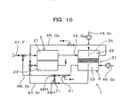
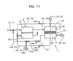
- Example shown in Figures 9 to 11 is another variation in which the O/C and S/C ratios are adjusted by feeding a particular oxygen-containing gas to the cathode offgas line 46 from a unit in the fuel cell system 1 or outside of the fuel cell system 1, for increase in the oxygen concentration in the reforming reaction channel 21.
- the cathode offgas Oc and the particular gas are mixed in the cathode offgas line 46, and the cathode offgas Oc adjusted in oxygen concentration is then fed into the reforming reaction channel 21.
- a cathode offgas three-way regulating valve 61 is also placed on the cathode offgas line 46 in the present Example.
- the fuel cell system 1 may be configured to mix part of the oxygen-containing refrigerant gas Gr sent to the refrigerant channel 34 with the cathode offgas Oc flowing in the cathode offgas line 46 and send the mixed gas thus obtained to the reforming reaction channel 21, as shown in Figure 9 .
- a refrigerant-gas three-way regulating valve 72 is placed on the refrigerant gas feed line 44.
- the relief port of the refrigerant-gas three-way regulating valve 72 is connected to the cathode offgas line 46 via a refrigerant gas mixing line 48G, and a refrigerant gas-cathode offgas mixing valve 88G is installed in the connection portion.
- Part of the oxygen-containing refrigerant gas Gr flowing in the refrigerant gas flowing in the line 44 can be mixed with the cathode offgas Oc flowing in the cathode offgas line 46.
- the fuel cell system 1 may be configured to mix part of the refrigerant offgas Or discharged from the refrigerant channel 34 with the cathode offgas flowing in the cathode offgas line 46 and send the mixed gas obtained to the reforming reaction channel 21, as shown in Figure 10 .
- the relief port of the refrigerant-offgas three-way regulating valve 71 placed on the refrigerant offgas line 47 is connected to the cathode offgas line 46 via a refrigerant offgas mixing line 48H, and a refrigerant offgas-cathode offgas mixing valve 88H is installed in the connection portion.
- Part of the refrigerant offgas Or flowing in the refrigerant offgas line 47 can be mixed with the cathode offgas Oc flowing in the cathode offgas line 46.
- the two refrigerant-offgas three-way regulating valves 71 may be installed on the refrigerant offgas line 47, and one is used for adjustment of the flow rate of the refrigerant offgas Or flowing in the refrigerant offgas line 47 and the other for mixing of the gases.
- the fuel cell system 1 may be configured to mix air by supplying air into the cathode offgas line 46 by an air pump 63, as shown in Figure 11 .
- the ejection nozzle of the air pump 63 is connected to the cathode offgas line 46, and a cathode offgas mixing valve 88I is installed in the connection portion.
- the air ejected by the air pump 63 is mixed with the cathode offgas Oc flowing in the cathode offgas line 46.
- the air pump 63 may be replaced with an oxygen buffer, also in such a case. It is possible then to increase the oxygen amount in the cathode offgas Oc for use in the reforming reaction channel 21 further effectively.
- Example 1 The other components in the present Example are the same as those in Example 1 above, and it is possible to obtain operational advantages similar to those of Example 1 above.
- the present Example is a variation in which the O/C and S/C rates in the reforming reaction channel 21 of the reformer 2 are adjusted by supplying a particular hydrogen-containing particular gas or fuel from a unit in the fuel cell system 1 or outside the fuel cell system 1 to the cathode offgas line 46, combusting it with the oxygen in the cathode offgas Oc, and thus, adjusting the oxygen amount in the cathode offgas Oc and water content.
- a cathode offgas Oc previously adjusted in oxygen concentration by combusting the cathode offgas Oc and the particular gas or fuel in the cathode offgas line 46 are supplied into the reforming reaction channel 21.
- a cathode offgas three-way regulating valve 61 is installed on the cathode offgas line 46, also in the present Example.
- the fuel cell system 1 may be configured to mix reforming fuel F in the cathode offgas line 46, as shown in Figure 12 .
- the feed line of the reforming fuel F is connected to the cathode offgas line 46, and a fuel-cathode offgas mixing valve 88J is installed in the connection portion.
- the reforming fuel F can thus be mixed with the cathode offgas Oc flowing in the cathode offgas line 46.
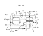
- the fuel cell system 1 may be configured to mix part of the anode offgas Oa flowing in the anode offgas line 45 into the cathode offgas line 46, as shown in Figure 13 ,
- the relief port of the anode offgas three-way regulating valve 51 placed on the anode offgas line 45 is connected to the cathode offgas line 46 via an anode offgas mixing line 48K, and an anode offgas-cathode offgas mixing valve 88K is installed in the connection portion.
- Part of the anode offgas Oa flowing in the anode offgas line 45 can thus be mixed with the cathode offgas Oc flowing in the cathode offgas line 46.
- Two anode offgas three-way regulating valve 51 may be placed on the anode offgas line 45, and one is used for adjustment of the flow rate of the anode offgas Oa flowing in the anode offgas line 45 and the other for mixing.
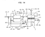
- the fuel cell system 1 may be configure to mix part of the hydrogen-containing reformed gas Ga flowing in the reformed-gas feed line 42 into the cathode offgas line 46, as shown in Figure 14 .
- a reformed-gas three-way regulating valve 53 is placed on the reformed-gas feed line 42. And, the relief port of the reformed-gas three-way regulating valve 53 is connected to the cathode offgas line 46 via a reformed-gas mixing line 48A, and a reformed-gas cathode-offgas mixing valve 88A is installed in the connection portion. Part of the hydrogen-containing reformed gas Ga flowing in the reformed-gas feed line 42 can thus be mixed with the cathode offgas Oc flowing in the cathode offgas line 46.
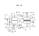
- the fuel cell system 1 may be configured to mix the hydrogen from the hydrogen buffer 83 into the cathode offgas line 46, as shown in Figure 15 .
- the hydrogen buffer 83 is connected to the cathode offgas line 46, and a hydrogen-cathode offgas mixing valve 88L is installed in the connection portion.
- the hydrogen stored in the hydrogen buffer 83 can be mixed with the cathode offgas Oc flowing in the cathode offgas line 46.
- the hydrogen buffer 83 may be, for example, a hydrogen cylinder, a hydrogen-absorbing alloy, carbon, or the like.
- Example 1 The other components in the present Example are the same as those in Example 1 above, and it is possible to obtain operational advantages similar to those of Example 1 above.
- the Example shown in Figures 16 to 18 is a variation in which the reforming fuel F is supplied into the reformer 2 via a mixed 92 connected to the cathode offgas line 46 and the air line 90.
- the mixer 92 above is connected to the fuel feed line 41 and communicate with the reformer 2, and the reforming fuel F is mixed with other gases in the mixer 92 and the mixed gas is supplied to the reformer 2. As shown in Figures 16 to 18 , it is possible to supply at least the cathode offgas Oc, the oxygen-containing gas Gc and the reforming fuel F to the mixer 92 and to supply the mixed gas into the reformer 2.
- the air line 90 is connected to a mixer 92 and an oxygen-containing gas feed line 43 for supply of the oxygen-containing gas Gc to the mixer 92.
- an air-flow-rate control valve 94 is installed on the air line 90, for control of the feed rate of the oxygen-containing gas Gc to the mixer 92.
- An oxygen-containing gas Gc is supplied to the mixer 92 in the present Example, but a discharge EGR gas such as the anode offgas Oa or the combustion offgas may be supplied instead to the mixer 92.
- the fuel cell system 1 supplies the oxygen-containing gas Gc supplied from the oxygen-containing gas feed line 43 to the mixer 92, and a mixed gas of the reforming fuel F, cathode offgas Oc, and oxygen-containing gas Gc into the reformer 2.
- the fuel cell system 1 may be configured to supply steam to the mixer 92 from outside, as shown in Figure 17 .
- the mixed gas discharged from the mixer 92 may be supplied to the reformer 2 and at the same time, the cathode offgas Oc is supplied directly to the reformer 2, as shown in Figure 18 .
- the mixed gas discharged from the mixer 92 is supplied via the cathode offgas mixing valve 98 to the reformer 2; the cathode offgas line 46 is connected to the cathode offgas mixing valve 100; and the cathode offgas mixing valve 98 is formed in communication with the cathode offgas mixing valve 100 via a direct line 102.
- part or all of the cathode offgas Oc can be supplied to the mixer 92 via the cathode offgas mixing valve 100, and part or all of the cathode offgas Oc directly to the reformer 2.
- the flow rate of the reforming fuel F is smaller than that of the cathode offgas, and thus, the cathode offgas flows predominantly in the mixer 92 during the passage period.
- Example 1 The other components in the present Example are the same as those in Example 1 above, and it is possible to obtain operational advantages similar to those of Example 1 above.
- the present invention provides a fuel cell system simpler in structure that allows recovery of all water generated in the cathode channel and improvement in energy efficiency further by using the remaining oxygen and the high-temperature heat energy of the cathode offgas, and a method of generating electricity thereby.
Landscapes
- Engineering & Computer Science (AREA)
- Chemical & Material Sciences (AREA)
- Life Sciences & Earth Sciences (AREA)
- Sustainable Development (AREA)
- Manufacturing & Machinery (AREA)
- Sustainable Energy (AREA)
- Chemical Kinetics & Catalysis (AREA)
- Electrochemistry (AREA)
- General Chemical & Material Sciences (AREA)
- Combustion & Propulsion (AREA)
- Fuel Cell (AREA)
Claims (21)
- Système de pile à combustible (1), comprenant un reformeur (2) ayant un canal de réaction de reformage (21) générant un gaz reformé contenant de l'hydrogène (Ga) contenant de l'hydrogène à partir d'un combustible de reformage (F) et une pile à combustible (3) générant de l'électricité en utilisant le gaz reformé contenant de l'hydrogène (Ga), dans lequel :la pile à combustible (3) comprend un canal d'anode (32) vers lequel le gaz reformé contenant de l'hydrogène (Ga) est alimenté depuis le canal de réaction de reformage (21), un canal de cathode (33) vers lequel un gaz contenant de l'oxygène (Gc) est alimenté, et un électrolyte (31) placé entre les canaux de cathode et d'anode (33, 32) ;l'électrolyte (31) comprend un laminé d'une couche de métal de séparation d'hydrogène (311) permettant la perméation de l'hydrogène dans le gaz reformé contenant de l'hydrogène (Ga) alimenté dans le canal d'anode (32) et une couche conductrice de proton (312) constituée d'un matériau céramique convertissant l'hydrogène traversant par perméation la couche de métal de séparation d'hydrogène (311) à l'état de proton, et laissant celui-ci atteindre le canal de cathode (33) ; etune voie de gaz de dégagement de cathode (46) pour alimenter le gaz de dégagement de cathode (Oc) déchargé depuis le canal de cathode (33) dans le canal de réaction de reformage (21) du reformeur (2) est raccordé au canal de cathode (33) de la pile à combustible (3), la voie de gaz de dégagement de cathode (46) alimentant le gaz de dégagement de cathode (Oc) dans le canal de réaction de reformage (21) non via un mélangeur mélangeant uniquement le gaz de dégagement de cathode (Oc) avec le combustible de reformage (F) ou un mélangeur mélangeant uniquement le gaz de dégagement de cathode (Oc) avec le combustible de reformage (F) et de la vapeur (St).
- Système de pile à combustible (1) selon la revendication 1, dans lequel le reformeur (2) comprend un canal d'échange de chaleur (22) qui est formé à proximité du canal de réaction de reformage (21) et qui chauffe le canal de réaction de reformage (21) par combustion.
- Système de pile à combustible (1) selon la revendication 2, dans lequel une voie de gaz de dégagement d'anode (45) pour alimenter un gaz de dégagement d'anode (Oa) déchargé depuis le canal d'anode (32) dans le canal d'échange de chaleur (22) est raccordée au canal d'anode (32) de la pile à combustible (3).
- Système de pile à combustible (1) selon l'une quelconque des revendications 1 à 3, dans lequel la pile à combustible (3) comprend un canal de réfrigérant (34) vers lequel un gaz réfrigérant contenant de l'oxygène (Gr) pour refroidir la pile à combustible (3) est alimenté.
- Système de pile à combustible (1) selon la revendication 4, dans lequel une voie de gaz de dégagement réfrigérant (47) pour alimenter un gaz de dégagement réfrigérant (Or) déchargé depuis le canal de réfrigérant (34) dans le canal d'échange de chaleur (22) est raccordé au canal de réfrigérant (34) de la pile à combustible (3).
- Système de pile à combustible (1) selon l'une quelconque des revendications 1 à 5, dans lequel une vanne de régulation à trois voies d'échappement (61) est installée sur la voie de gaz de dégagement de cathode (46), une partie du gaz de dégagement de cathode (Oc) est déchargée via la vanne de régulation d'échappement trois voies (61), et une partie résiduelle du gaz de dégagement de cathode (Oc) est alimentée dans le canal de réaction de reformage (21).
- Système de pile à combustible (1) selon l'une quelconque des revendications 2 à 6, dans lequel une vanne de référence à trois voies d'alimentation (611) est installée sur la voie de gaz de dégagement de cathode (46), une partie du gaz de dégagement de cathode (Oc) est alimentée dans le canal d'échange de chaleur (22) via la vanne de régulation d'alimentation trois voies (611), et une partie résiduelle du gaz de dégagement de cathode (Oc) est alimentée dans le canal de réaction de reformage (21).
- Système de pile à combustible (1) selon l'une quelconque des revendications 1 à 6, dans lequel une vanne de régulation à trois voies de réalimentation (612) est installée sur la voie de gaz de dégagement de cathode (46), une partie du gaz de dégagement de cathode (Oc) est réalimentée dans le canal de cathode (33) via la vanne de régulation trois voies de réalimentation (612), et une partie résiduelle du gaz de dégagement de cathode (Oc) est alimentée dans le canal de réaction de reformage (21).
- Système de pile à combustible (1) selon l'une quelconque des revendications 1 à 6, dans lequel une membrane de séparation d'oxygène (81) est installée sur la voie de gaz de dégagement de cathode (46), et une partie d'oxygène dans le gaz de dégagement de cathode (Oc) est déchargée à travers la membrane de séparation d'oxygène (81).
- Système de pile à combustible (1) selon l'une quelconque des revendications 1 à 6, dans lequel une membrane de séparation d'oxygène (81) est installée sur la voie de gaz de dégagement de cathode (46), et une partie d'oxygène dans le gaz de dégagement de cathode (Oc) est réalimentée dans le canal de cathode (33) à travers la membrane de séparation d'oxygène (81).
- Système de pile à combustible (1) selon l'une quelconque des revendications 2 à 6, dans lequel une membrane de séparation d'oxygène (81) est installée sur la voie de gaz de dégagement de cathode (46), et une partie d'oxygène dans le gaz de dégagement de cathode (Oc) est alimentée dans le canal d'échange de chaleur (22) à travers la membrane de séparation d'oxygène (81).
- Système de pile à combustible (1) selon l'une quelconque des revendications 1 à 6, dans lequel une membrane de séparation d'oxygène (81) est installée sur la voie de gaz de dégagement de cathode (46), et une partie d'oxygène dans le gaz de dégagement de cathode (Oc) est stockée dans un tampon d'oxygène (82) à travers la membrane de séparation d'oxygène (81).
- Système de pile à combustible (1) selon l'une quelconque des revendications 4 à 12, dans lequel une partie du gaz réfrigérant contenant de l'oxygène (Gr) est mélangée dans la voie de gaz de dégagement de cathode (46).
- Système de pile à combustible (1) selon l'une quelconque des revendications 5 à 12, dans lequel une partie du gaz de dégagement réfrigérant (Or) est mélangée dans la voie de gaz de dégagement de cathode (46).
- Système de pile à combustible (1) selon l'une quelconque des revendications 1 à 12, dans lequel de l'air est mélangé dans la voie de gaz de dégagement de cathode (46).
- Système de pile à combustible (1) selon l'une quelconque des revendications 1 à 12, dans lequel de l'oxygène est mélangé dans la voie de gaz de dégagement de cathode (46).
- Système de pile à combustible (1) selon l'une quelconque des revendications 3 à 12, dans lequel une partie du gaz de dégagement d'anode (Oa) est mélangée dans la voie de gaz de dégagement de cathode (46).
- Système de pile à combustible (1) selon l'une quelconque des revendications 1 à 12, dans lequel une partie du gaz reformé contenant de l'hydrogène (Ga) est mélangée dans la voie de gaz de dégagement de cathode (46).
- Système de pile à combustible (1) selon l'une quelconque des revendications 1 à 12, dans lequel de l'hydrogène est mélangé dans la voie de gaz de dégagement de cathode (46).
- Procédé de génération d'électricité dans un système de pile à combustible (1) comprenant un reformeur (2) ayant un canal de réaction de reformage (21) générant un gaz reformé contenant de l'hydrogène (Ga) contenant de l'hydrogène provenant d'un combustible de reformage (F) et une pile à combustible (3) générant de l'électricité en utilisant le gaz reformé contenant de l'hydrogène (Ga), dans lequel la pile à combustible (3) comprend un canal d'anode (32) dans lequel le gaz reformé contenant de l'hydrogène (Ga) est alimenté depuis le canal de réaction de reformage (21), un canal de cathode (33) dans lequel un gaz contenant de l'oxygène (Gc) est alimenté, et un électrolyte (31) placé entre les canaux de cathode et d'anode (33, 32), et l'électrolyte (31) est un laminé d'une couche de métal de séparation d'hydrogène (311) permettant la perméation de l'hydrogène dans le gaz reformé contenant de l'hydrogène (Ga) alimenté dans le canal d'anode (32) et une couche conductrice de proton (312) constituée d'un matériau céramique convertissant l'hydrogène traversant par perméation la couche de métal de séparation d'hydrogène (311) à l'état de proton et laissant celui-ci atteindre le canal de cathode (33) ; et le procédé comprenant les étapes consistant à :alimenter le gaz reformé contenant de l'hydrogène (Ga) généré dans le canal de réaction de reformage (21) dans le canal d'anode (32);laisser l'hydrogène dans le gaz reformé contenant de l'hydrogène (Ga) passer par perméation depuis le canal d'anode (32) à travers la couche de métal de séparation d'hydrogène (311) et atteindre le canal de cathode (33) à travers la couche conductrice de proton (312) à l'état de proton ; etlaisser le proton réagir avec l'oxygène dans le gaz contenant de l'oxygène (Gc) dans le canal de cathode (33), en générant de l'électricité ; et en outre,alimenter un gaz de dégagement de cathode (Oc) déchargé depuis le canal de cathode (33) vers le canal de réaction de reformage (21); etlaisser le combustible de reformage (F) réagir avec le gaz de dégagement de cathode (Oc), en générant le gaz reformé contenant de l'hydrogène (Ga) dans le canal de réaction de reformage (21), dans lequel le gaz de dégagement de cathode (Oc) est alimenté par l'intermédiaire de la voie de gaz de dégagement de cathode (46) dans le canal de réaction de reformage (21) non via un mélangeur mélangeant uniquement le gaz de dégagement de cathode (Oc) avec le combustible de reformage (F) ou un mélangeur mélangeant uniquement le gaz de dégagement de cathode (Oc) avec le combustible de reformage (F) et de la vapeur (St).
- Procédé de génération d'électricité dans un système de pile à combustible (1) selon la revendication 20, dans lequel :le reformeur (2) comprend un canal d'échange de chaleur (22) qui est formé à proximité du canal de réaction de reformage (21) et qui chauffe le canal de réaction de reformage (21) par combustion ;la pile à combustible (3) a un canal de réfrigérant (34) dans lequel un gaz réfrigérant contenant de l'oxygène (Gr) pour refroidir la pile à combustible (3) est alimenté ; et le procédé comprenant :le chauffage est effectué par alimentation d'un gaz de dégagement d'anode (Oa) déchargé depuis le canal d'anode (32) et un gaz de dégagement de réfrigérant (Or) déchargé depuis le canal de réfrigérant (34) vers le canal d'échange de chaleur (22), et la combustion du gaz de dégagement d'anode (Oa) avec le gaz de dégagement de réfrigérant (Or) dans le canal d'échange de chaleur (22).
Applications Claiming Priority (2)
| Application Number | Priority Date | Filing Date | Title |
|---|---|---|---|
| JP2004007227 | 2004-01-14 | ||
| PCT/JP2005/000720 WO2005069416A1 (fr) | 2004-01-14 | 2005-01-14 | Systeme de pile a combustible et son procede de production d'energie |
Publications (3)
| Publication Number | Publication Date |
|---|---|
| EP1715540A1 EP1715540A1 (fr) | 2006-10-25 |
| EP1715540A4 EP1715540A4 (fr) | 2011-04-27 |
| EP1715540B1 true EP1715540B1 (fr) | 2013-05-22 |
Family
ID=34792173
Family Applications (1)
| Application Number | Title | Priority Date | Filing Date |
|---|---|---|---|
| EP05703948.9A Expired - Lifetime EP1715540B1 (fr) | 2004-01-14 | 2005-01-14 | Dispositif de génération d'énergie par pile à combustible |
Country Status (5)
| Country | Link |
|---|---|
| US (1) | US20070065688A1 (fr) |
| EP (1) | EP1715540B1 (fr) |
| JP (1) | JP4491653B2 (fr) |
| CN (1) | CN100411233C (fr) |
| WO (1) | WO2005069416A1 (fr) |
Families Citing this family (18)
| Publication number | Priority date | Publication date | Assignee | Title |
|---|---|---|---|---|
| JP4523298B2 (ja) * | 2004-02-10 | 2010-08-11 | 株式会社豊田中央研究所 | 燃料電池システム及びその発電方法 |
| JP4523297B2 (ja) * | 2004-02-10 | 2010-08-11 | 株式会社豊田中央研究所 | 燃料電池システム及びその発電方法 |
| DE102008008907B4 (de) * | 2008-02-13 | 2021-11-04 | Eberspächer Climate Control Systems GmbH & Co. KG | Brennstoffzellensystem |
| JP5572967B2 (ja) * | 2009-03-06 | 2014-08-20 | 日産自動車株式会社 | 燃料電池システムと、この燃料電池システムの運転方法 |
| FI20105962A7 (fi) * | 2010-09-17 | 2012-03-18 | Convion Oy | Menetelmä ja järjestely anodioksidoinnin välttämiseksi |
| EP3012894B1 (fr) * | 2013-06-17 | 2019-08-28 | Hitachi Zosen Corporation | Procédé d'économie d'énergie dans un système combiné possédant un dispositif de fabrication de bioéthanol et une pile à combustible à oxyde solide combinés en son sein |
| KR102506452B1 (ko) * | 2015-10-26 | 2023-03-07 | 삼성전자주식회사 | 공기 재순환을 통해 산소 농도를 유지하는 전기화학 전지 |
| KR102212137B1 (ko) | 2016-04-21 | 2021-02-03 | 퓨얼 셀 에너지, 인크 | 이산화탄소 포획을 위해 용융 탄산염 연료 전지 애노드 배기를 후가공처리하는 방법 |
| CN109314261B (zh) | 2016-04-29 | 2023-01-31 | 燃料电池能有限公司 | 甲烷化阳极废气以提高二氧化碳捕获 |
| CN108172868B (zh) * | 2016-12-07 | 2020-03-10 | 中国科学院大连化学物理研究所 | 一种燃料电池系统水管理组件 |
| JP6847900B2 (ja) * | 2018-08-20 | 2021-03-24 | 東京瓦斯株式会社 | 二酸化炭素回収型燃料電池発電システム |
| AU2019388977B2 (en) | 2018-11-30 | 2025-01-30 | ExxonMobil Technology and Engineering Company | Flow field baffle for molten carbonate fuel cell cathode |
| US12355085B2 (en) | 2018-11-30 | 2025-07-08 | ExxonMobil Technology and Engineering Company | Cathode collector structures for molten carbonate fuel cell |
| US11742508B2 (en) | 2018-11-30 | 2023-08-29 | ExxonMobil Technology and Engineering Company | Reforming catalyst pattern for fuel cell operated with enhanced CO2 utilization |
| CA3162614C (fr) | 2019-11-26 | 2024-03-26 | Exxonmobile Research And Engineering Company | Ensemble module de pile a combustible et systemes utilisant ledit ensemble module de pile a combustible |
| EP4066303A1 (fr) | 2019-11-26 | 2022-10-05 | ExxonMobil Technology and Engineering Company | Ensemble pile à combustible à collecteur externe pour écoulement parallèle |
| WO2021181249A1 (fr) | 2020-03-11 | 2021-09-16 | Fuelcell Energy, Inc. | Unité de reformage de méthane à la vapeur pour la capture de carbone |
| CN112164817A (zh) * | 2020-09-03 | 2021-01-01 | 浙江科技学院 | 一种固体氧化物燃料电池发电系统 |
Family Cites Families (11)
| Publication number | Priority date | Publication date | Assignee | Title |
|---|---|---|---|---|
| US3990912A (en) * | 1972-07-17 | 1976-11-09 | United Technologies Corporation | Electrolyte regeneration in a fuel cell stack |
| JPH04345762A (ja) * | 1991-05-24 | 1992-12-01 | Nippon Telegr & Teleph Corp <Ntt> | ガス分離膜式燃料電池 |
| JPH05299105A (ja) * | 1992-04-23 | 1993-11-12 | Mitsubishi Heavy Ind Ltd | 燃料電池 |
| US6656617B2 (en) * | 2000-01-24 | 2003-12-02 | Toyota Jidosha Kabushiki Kaisha | Fuel gas production system for fuel cells |
| NZ524476A (en) * | 2000-07-31 | 2005-11-25 | Nuvant Systems Inc | Hydrogen permeable membrane for use in fuel cells, and partial reformate fuel cell system having reforming catalysts in the anode fuel cell compartment |
| JP2002289245A (ja) * | 2001-03-23 | 2002-10-04 | Toyota Motor Corp | 改質部を備える燃料電池システム |
| JP3915478B2 (ja) * | 2001-11-09 | 2007-05-16 | トヨタ自動車株式会社 | 燃料電池システム |
| JP4096575B2 (ja) * | 2002-02-15 | 2008-06-04 | 日産自動車株式会社 | 燃料電池システム |
| JP4079016B2 (ja) * | 2002-08-28 | 2008-04-23 | トヨタ自動車株式会社 | 中温域で作動可能な燃料電池 |
| JP4543612B2 (ja) * | 2003-03-11 | 2010-09-15 | トヨタ自動車株式会社 | 燃料電池システム |
| US20050186455A1 (en) * | 2003-06-27 | 2005-08-25 | Ultracell Corporation, A California Corporation | Micro fuel cell system start up and shut down systems and methods |
-
2005
- 2005-01-14 EP EP05703948.9A patent/EP1715540B1/fr not_active Expired - Lifetime
- 2005-01-14 WO PCT/JP2005/000720 patent/WO2005069416A1/fr not_active Ceased
- 2005-01-14 CN CNB2005800024344A patent/CN100411233C/zh not_active Expired - Fee Related
- 2005-01-14 JP JP2005517131A patent/JP4491653B2/ja not_active Expired - Fee Related
-
2006
- 2006-07-14 US US11/486,011 patent/US20070065688A1/en not_active Abandoned
Also Published As
| Publication number | Publication date |
|---|---|
| JP4491653B2 (ja) | 2010-06-30 |
| EP1715540A4 (fr) | 2011-04-27 |
| JPWO2005069416A1 (ja) | 2007-09-06 |
| CN1910774A (zh) | 2007-02-07 |
| EP1715540A1 (fr) | 2006-10-25 |
| US20070065688A1 (en) | 2007-03-22 |
| WO2005069416A1 (fr) | 2005-07-28 |
| CN100411233C (zh) | 2008-08-13 |
Similar Documents
| Publication | Publication Date | Title |
|---|---|---|
| CN110710040B (zh) | 生产氢气、电力和联产的方法和系统 | |
| EP1715540A1 (fr) | Systeme de pile a combustible et son procede de production d'energie | |
| EP1908144B1 (fr) | Systeme de piles a combustible a recyclage electrochimique de l'echappement cote anode | |
| US7846599B2 (en) | Method for high temperature fuel cell system start up and shutdown | |
| US12341229B2 (en) | Solid oxide fuel cell system with hydrogen pumping cell with carbon monoxide tolerant anodes and integrated shift reactor | |
| KR20210141982A (ko) | 일산화탄소 내성 애노드 및 통합된 시프트 반응기를 구비한 수소 펌핑 전지를 갖는 고체 산화물 연료 전지 시스템 | |
| US8883370B2 (en) | Fuel cell system operated with liquid gas | |
| US20090155637A1 (en) | System and process for generating electrical power | |
| US20090208785A1 (en) | SOFC electrochemical anode tail gas oxidizer | |
| JP5763405B2 (ja) | 燃料電池システム | |
| US20090068512A1 (en) | Hydrogen refueling station | |
| KR20200116957A (ko) | 이산화탄소 제조 시스템 | |
| JP6061892B2 (ja) | 燃料電池発電システム | |
| EP3573159A1 (fr) | Système de pile à combustible et son procédé de fonctionnement | |
| JP4523298B2 (ja) | 燃料電池システム及びその発電方法 | |
| EP4195337A1 (fr) | Système de pile à combustible et son procédé de fonctionnement à une utilisation de combustible proche du cent pour cent | |
| US20090155640A1 (en) | System and process for generating electrical power | |
| JP4523297B2 (ja) | 燃料電池システム及びその発電方法 | |
| JP6993488B1 (ja) | 燃料電池発電システム、及び、燃料電池発電システムの制御方法 | |
| JP2007141772A (ja) | 燃料電池システム | |
| GB2405028A (en) | Method and device for operating an immediate temperature solid oxide fuel cell | |
| JP7236364B2 (ja) | 燃料電池ユニット、及び燃料電池システム | |
| KR100814434B1 (ko) | 용융탄산염 연료전지 발전플랜트의 차압제어방법 | |
| WO2021053944A1 (fr) | Unité de pile à combustible, système de pile à combustible et méthode de récupération de dioxyde de carbone |
Legal Events
| Date | Code | Title | Description |
|---|---|---|---|
| PUAI | Public reference made under article 153(3) epc to a published international application that has entered the european phase |
Free format text: ORIGINAL CODE: 0009012 |
|
| 17P | Request for examination filed |
Effective date: 20060720 |
|
| AK | Designated contracting states |
Kind code of ref document: A1 Designated state(s): DE FR GB IT |
|
| DAX | Request for extension of the european patent (deleted) | ||
| RBV | Designated contracting states (corrected) |
Designated state(s): DE FR GB IT |
|
| A4 | Supplementary search report drawn up and despatched |
Effective date: 20110330 |
|
| 17Q | First examination report despatched |
Effective date: 20110727 |
|
| GRAP | Despatch of communication of intention to grant a patent |
Free format text: ORIGINAL CODE: EPIDOSNIGR1 |
|
| RAP1 | Party data changed (applicant data changed or rights of an application transferred) |
Owner name: TOYOTA JIDOSHA KABUSHIKI KAISHA |
|
| GRAS | Grant fee paid |
Free format text: ORIGINAL CODE: EPIDOSNIGR3 |
|
| GRAA | (expected) grant |
Free format text: ORIGINAL CODE: 0009210 |
|
| AK | Designated contracting states |
Kind code of ref document: B1 Designated state(s): DE FR GB IT |
|
| REG | Reference to a national code |
Ref country code: GB Ref legal event code: FG4D |
|
| REG | Reference to a national code |
Ref country code: DE Ref legal event code: R096 Ref document number: 602005039678 Country of ref document: DE Effective date: 20130718 |
|
| PLBE | No opposition filed within time limit |
Free format text: ORIGINAL CODE: 0009261 |
|
| STAA | Information on the status of an ep patent application or granted ep patent |
Free format text: STATUS: NO OPPOSITION FILED WITHIN TIME LIMIT |
|
| 26N | No opposition filed |
Effective date: 20140225 |
|
| REG | Reference to a national code |
Ref country code: DE Ref legal event code: R097 Ref document number: 602005039678 Country of ref document: DE Effective date: 20140225 |
|
| REG | Reference to a national code |
Ref country code: DE Ref legal event code: R084 Ref document number: 602005039678 Country of ref document: DE |
|
| REG | Reference to a national code |
Ref country code: GB Ref legal event code: 746 Effective date: 20141023 |
|
| REG | Reference to a national code |
Ref country code: DE Ref legal event code: R084 Ref document number: 602005039678 Country of ref document: DE Effective date: 20141021 |
|
| REG | Reference to a national code |
Ref country code: FR Ref legal event code: PLFP Year of fee payment: 12 |
|
| REG | Reference to a national code |
Ref country code: FR Ref legal event code: PLFP Year of fee payment: 13 |
|
| PGFP | Annual fee paid to national office [announced via postgrant information from national office to epo] |
Ref country code: FR Payment date: 20161215 Year of fee payment: 13 |
|
| PGFP | Annual fee paid to national office [announced via postgrant information from national office to epo] |
Ref country code: DE Payment date: 20170110 Year of fee payment: 13 |
|
| PGFP | Annual fee paid to national office [announced via postgrant information from national office to epo] |
Ref country code: GB Payment date: 20170111 Year of fee payment: 13 |
|
| PGFP | Annual fee paid to national office [announced via postgrant information from national office to epo] |
Ref country code: IT Payment date: 20170123 Year of fee payment: 13 |
|
| REG | Reference to a national code |
Ref country code: DE Ref legal event code: R119 Ref document number: 602005039678 Country of ref document: DE |
|
| GBPC | Gb: european patent ceased through non-payment of renewal fee |
Effective date: 20180114 |
|
| PG25 | Lapsed in a contracting state [announced via postgrant information from national office to epo] |
Ref country code: FR Free format text: LAPSE BECAUSE OF NON-PAYMENT OF DUE FEES Effective date: 20180131 Ref country code: DE Free format text: LAPSE BECAUSE OF NON-PAYMENT OF DUE FEES Effective date: 20180801 |
|
| REG | Reference to a national code |
Ref country code: FR Ref legal event code: ST Effective date: 20180928 |
|
| PG25 | Lapsed in a contracting state [announced via postgrant information from national office to epo] |
Ref country code: GB Free format text: LAPSE BECAUSE OF NON-PAYMENT OF DUE FEES Effective date: 20180114 |
|
| PG25 | Lapsed in a contracting state [announced via postgrant information from national office to epo] |
Ref country code: IT Free format text: LAPSE BECAUSE OF NON-PAYMENT OF DUE FEES Effective date: 20180114 |