EP1717075A1 - Klimaanlage - Google Patents
Klimaanlage Download PDFInfo
- Publication number
- EP1717075A1 EP1717075A1 EP05709729A EP05709729A EP1717075A1 EP 1717075 A1 EP1717075 A1 EP 1717075A1 EP 05709729 A EP05709729 A EP 05709729A EP 05709729 A EP05709729 A EP 05709729A EP 1717075 A1 EP1717075 A1 EP 1717075A1
- Authority
- EP
- European Patent Office
- Prior art keywords
- compression
- compression mechanism
- displacement
- evaporator
- temperature
- Prior art date
- Legal status (The legal status is an assumption and is not a legal conclusion. Google has not performed a legal analysis and makes no representation as to the accuracy of the status listed.)
- Withdrawn
Links
Images


Classifications
-
- B—PERFORMING OPERATIONS; TRANSPORTING
- B60—VEHICLES IN GENERAL
- B60H—ARRANGEMENTS OF HEATING, COOLING, VENTILATING OR OTHER AIR-TREATING DEVICES SPECIALLY ADAPTED FOR PASSENGER OR GOODS SPACES OF VEHICLES
- B60H1/00—Heating, cooling or ventilating devices
- B60H1/32—Cooling devices
- B60H1/3204—Cooling devices using compression
- B60H1/3205—Control means therefor
- B60H1/3211—Control means therefor for increasing the efficiency of a vehicle refrigeration cycle
-
- B—PERFORMING OPERATIONS; TRANSPORTING
- B60—VEHICLES IN GENERAL
- B60H—ARRANGEMENTS OF HEATING, COOLING, VENTILATING OR OTHER AIR-TREATING DEVICES SPECIALLY ADAPTED FOR PASSENGER OR GOODS SPACES OF VEHICLES
- B60H1/00—Heating, cooling or ventilating devices
- B60H1/32—Cooling devices
- B60H1/3204—Cooling devices using compression
- B60H1/3205—Control means therefor
- B60H1/3208—Vehicle drive related control of the compressor drive means, e.g. for fuel saving purposes
-
- B—PERFORMING OPERATIONS; TRANSPORTING
- B60—VEHICLES IN GENERAL
- B60H—ARRANGEMENTS OF HEATING, COOLING, VENTILATING OR OTHER AIR-TREATING DEVICES SPECIALLY ADAPTED FOR PASSENGER OR GOODS SPACES OF VEHICLES
- B60H1/00—Heating, cooling or ventilating devices
- B60H1/32—Cooling devices
- B60H2001/3269—Cooling devices output of a control signal
- B60H2001/327—Cooling devices output of a control signal related to a compressing unit
-
- F—MECHANICAL ENGINEERING; LIGHTING; HEATING; WEAPONS; BLASTING
- F25—REFRIGERATION OR COOLING; COMBINED HEATING AND REFRIGERATION SYSTEMS; HEAT PUMP SYSTEMS; MANUFACTURE OR STORAGE OF ICE; LIQUEFACTION SOLIDIFICATION OF GASES
- F25B—REFRIGERATION MACHINES, PLANTS OR SYSTEMS; COMBINED HEATING AND REFRIGERATION SYSTEMS; HEAT PUMP SYSTEMS
- F25B2400/00—Component parts or details not otherwise provided for in this subclass
- F25B2400/07—Details of compressors or related parts
- F25B2400/075—Details of compressors or related parts with parallel compressors
- F25B2400/0751—Details of compressors or related parts with parallel compressors the compressors having different capacities
-
- F—MECHANICAL ENGINEERING; LIGHTING; HEATING; WEAPONS; BLASTING
- F25—REFRIGERATION OR COOLING; COMBINED HEATING AND REFRIGERATION SYSTEMS; HEAT PUMP SYSTEMS; MANUFACTURE OR STORAGE OF ICE; LIQUEFACTION SOLIDIFICATION OF GASES
- F25B—REFRIGERATION MACHINES, PLANTS OR SYSTEMS; COMBINED HEATING AND REFRIGERATION SYSTEMS; HEAT PUMP SYSTEMS
- F25B2600/00—Control issues
- F25B2600/02—Compressor control
- F25B2600/025—Compressor control by controlling speed
- F25B2600/0253—Compressor control by controlling speed with variable speed
-
- F—MECHANICAL ENGINEERING; LIGHTING; HEATING; WEAPONS; BLASTING
- F25—REFRIGERATION OR COOLING; COMBINED HEATING AND REFRIGERATION SYSTEMS; HEAT PUMP SYSTEMS; MANUFACTURE OR STORAGE OF ICE; LIQUEFACTION SOLIDIFICATION OF GASES
- F25B—REFRIGERATION MACHINES, PLANTS OR SYSTEMS; COMBINED HEATING AND REFRIGERATION SYSTEMS; HEAT PUMP SYSTEMS
- F25B2700/00—Sensing or detecting of parameters; Sensors therefor
- F25B2700/21—Temperatures
- F25B2700/2104—Temperatures of an indoor room or compartment
-
- F—MECHANICAL ENGINEERING; LIGHTING; HEATING; WEAPONS; BLASTING
- F25—REFRIGERATION OR COOLING; COMBINED HEATING AND REFRIGERATION SYSTEMS; HEAT PUMP SYSTEMS; MANUFACTURE OR STORAGE OF ICE; LIQUEFACTION SOLIDIFICATION OF GASES
- F25B—REFRIGERATION MACHINES, PLANTS OR SYSTEMS; COMBINED HEATING AND REFRIGERATION SYSTEMS; HEAT PUMP SYSTEMS
- F25B2700/00—Sensing or detecting of parameters; Sensors therefor
- F25B2700/21—Temperatures
- F25B2700/2106—Temperatures of fresh outdoor air
-
- F—MECHANICAL ENGINEERING; LIGHTING; HEATING; WEAPONS; BLASTING
- F25—REFRIGERATION OR COOLING; COMBINED HEATING AND REFRIGERATION SYSTEMS; HEAT PUMP SYSTEMS; MANUFACTURE OR STORAGE OF ICE; LIQUEFACTION SOLIDIFICATION OF GASES
- F25B—REFRIGERATION MACHINES, PLANTS OR SYSTEMS; COMBINED HEATING AND REFRIGERATION SYSTEMS; HEAT PUMP SYSTEMS
- F25B2700/00—Sensing or detecting of parameters; Sensors therefor
- F25B2700/21—Temperatures
- F25B2700/2117—Temperatures of an evaporator
- F25B2700/21171—Temperatures of an evaporator of the fluid cooled by the evaporator
- F25B2700/21172—Temperatures of an evaporator of the fluid cooled by the evaporator at the inlet
Definitions
- the present invention relates to an air conditioner with a refrigeration cycle having a compressor for refrigerant, and more specifically, to an air conditioner suitable for controlling a refrigeration cycle having a fixed displacement compression mechanism and a variable displacement compression mechanism independent from each other.
- an object of the present invention is to enable a stable and adequate control for air conditioning for achieving a required cooling performance by carrying out optimum feedforward or/and feedback control even in different operation conditions, in an air conditioner with a refrigeration system having two compression mechanisms of one fixed displacement-type compression mechanism and the other variable displacement-type compression mechanism capable of being changed in displacement, and to provide an air conditioner suitable, for example, for a cabin of a work vehicle.
- an air conditioner has, in a refrigeration cycle, two compression mechanisms of a fixed displacement-type first compression mechanism and a variable displacement-type second compression mechanism independent from each other, and has second compression mechanism displacement control means for controlling a displacement of the second compression mechanism, compression mechanism operation switching control means for switching to an operation by the two compression mechanisms or an operation by any one compression mechanism, an evaporator for refrigerant for cooling air for air conditioning, a condenser for refrigerant, a blower for sending air to the evaporator, and second compression mechanism feedforward compression displacement calculation means for calculating a compression displacement for feedforward control in the second compression mechanism, and wherein, the second compression mechanism feedforward compression displacement calculation means calculates compression displacements for a time of sole operation of the second compression mechanism and a time of simultaneous operation of the first and second compression mechanisms, respectively, by using second compression mechanism feedforward compression displacement calculating equations different from each other (a first structure).
- an air conditioner has, in a refrigeration cycle, two compression mechanisms of a fixed displacement-type first compression mechanism and a variable displacement-type second compression mechanism independent from each other, and has second compression mechanism displacement control means for controlling a displacement of the second compression mechanism, compression mechanism operation switching control means for switching to an operation by the two compression mechanisms or an operation by any one compression mechanism, an evaporator for refrigerant for cooling air for air conditioning, a condenser for refrigerant, a blower for sending air to the evaporator, evaporator temperature detection means for detecting a temperature of the evaporator or a temperature of air at an exit of the evaporator, evaporator target temperature calculation means for calculating a target temperature of the evaporator temperature or the evaporator exit air temperature, and second compression mechanism feedback compression displacement calculation means for calculating a feedback compression displacement in the second compression mechanism by referring to a deviation between the evaporator temperature or the evaporator exit air temperature and the target temperature of the evaporator
- an air conditioner according to the present invention has, in a refrigeration cycle, two compression mechanisms of a fixed displacement-type first compression mechanism and a variable displacement-type second compression mechanism independent from each other, and has second compression mechanism displacement control means for controlling a displacement of the second compression mechanism, compression mechanism operation switching control means for switching to an operation by the two compression mechanisms or an operation by any one compression mechanism, an evaporator for refrigerant for cooling air for air conditioning, a condenser for refrigerant, a blower for sending air to the evaporator, second compression mechanism feedforward compression displacement calculation means for calculating a compression displacement for feedforward control in the second compression mechanism, evaporator temperature detection means for detecting a temperature of the evaporator or a temperature of air at an exit of the evaporator, evaporator target temperature calculation means for calculating a target temperature of the evaporator temperature or the evaporator exit air temperature, and second compression mechanism feedback compression displacement calculation means
- the displacement of the second compression mechanism is controlled by the second compression mechanism displacement control means to switch the compressor operation to the simultaneous operation, by referring to only the second compression mechanism feedforward compression displacement without referring to the feedback compression displacement calculated by the second compression mechanism feedback compression displacement calculation means.
- the second compression mechanism feedforward compression displacement calculation means calculates second compression mechanism feedforward compression displacements by referring to a thermal load to the refrigeration cycle for the time of sole operation of the second compression mechanism, and by referring to the thermal load to the refrigeration cycle and a rotational speed of a prime mover which is a drive source of the first compression mechanism or/and a running speed of a vehicle driven by the prime mover for the time of simultaneous operation of the first and second compression mechanisms, respectively.
- the above-described predetermined time may be calculated by a thermal load to the refrigeration cycle and a rotational speed of the prime mover which is a drive source of the first compression mechanism or/and a running speed of a vehicle driven by the prime mover.
- the above-described thermal load to the refrigeration cycle may be calculated by detecting an outside air temperature, an room interior temperature, an amount of blown air or a physical value having a correlation with the amount of blown air, and an amount of sunshine, or by detecting at least one of those.
- the above-described second compression mechanism may comprise a variable displacement compression mechanism controlled by a displacement control signal, or a variable displacement compression mechanism controlled by control of rotational speed.
- the air conditioner according to the present invention performing such a feedforward or/and feedback control is suitable as an air conditioner for vehicles, especially, as an air conditioner for work vehicles.
- an optimum feedforward or/and feedback control may be carried out even for an operation of the simultaneous operation or the sole operation of the second compression mechanism different from each other, and by this, it becomes possible to carry out a stable and adequate control for air conditioning for achieving a required cooling performance.
- Fig. 1 shows a schematic equipment disposition diagram of an air conditioner according to an embodiment of the present invention, for example, an air conditioner for work vehicles.
- air conditioner 1 depicted in Fig. 1 a blower 4 for sending air sucked through an introduction port 3 for outside air or/and inside air is provided at an upstream position in an air duct 2 opening toward a room interior (for example, the interior of a cabin).
- An evaporator 5 is provided at a position downstream blower 4 as a cooler for cooling air sent.
- a heater core as a heater may be provided downstream evaporator 5. The air having passed through evaporator 5 and having been cooled is blown into the room interior.
- Refrigeration cycle 6 is constructed as a refrigerant circuit in which respective equipment are connected via refrigerant tubes, and in this refrigeration cycle 6, provided are a fixed displacement-type first compression mechanism 9 whose drive source is a prime mover (for example, an engine), etc. and whose drive is controlled by a drive control signal 8 sent from a main controller 7, and a variable displacement-type second compression mechanism 12 whose discharge displacement signal 10 is sent to main controller 7 and whose displacement is controlled by a displacement control signal 11 sent from main controller 7.
- second compression mechanism 12 is driven by an electric motor.
- a condenser 13 for condensing high-temperature and high-pressure refrigerant compressed by first compression mechanism 9 and/or second compression mechanism 12, a liquid receiver 14 for separating the condensed refrigerant into gas and liquid phases, an expansion valve 15 for reducing in pressure and expanding the refrigerant sent from liquid receiver 14, and evaporator 5 for evaporating the refrigerant sent from expansion valve 15 and cooling the air sent in air duct 2 by heat exchange between the refrigerant and the air, are disposed in this order, and the refrigerant from evaporator 5 is sucked into the above-described compression mechanism and compressed again.
- the temperature control of evaporator 5 is carried out, for example, by the control of a clutch provided on a drive force transmitting route from the prime mover to the first compression mechanism 9 and a control signal for the electric motor for driving the second compression mechanism 12.
- signals of a vehicle interior temperature (Tin) detected by a vehicle interior temperature sensor 17, an outside air temperature (Tamb) detected by an outside air temperature sensor 18 and an amount of sunshine (Rsun) detected by a sunshine sensor 19 are also sent to main controller 7, respectively.
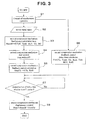
- main controller 7 for example, as shown in Figs. 2 and 3.
- the first compression mechanism 9 is a fixed displacement type, it is controlled by a clutch signal, and the clutch signal is calculated from an evaporator temperature target value (Toff) and an evaporator exit air temperature (Teva) detected by evaporator exit air temperature sensor 16 by the following equation.
- Clutch signal f Toff , Teva
- second compression mechanism 12 when second compression mechanism 12 is operated, the evaporator temperature control is carried out by its displacement control means, and it is controlled by controlling the variable displacement mechanism by displacement control signal 11 or by controlling the rotational speed of the electric motor provided for driving second compression mechanism 12.
- This control method of second compression mechanism 12 will be explained referring to Figs. 2 and 3.
- the compression displacement of second compression mechanism 12 is controlled by feed forward (FF) calculation term and feedback (FB) calculation term.
- FF and FB calculation terms have control manners adapted to operation conditions, respectively. In particular, they are given with a difference for the simultaneous operation of the first and second compression mechanisms as compared with the sole operation of the second compression mechanism.
- the control method of second compression mechanism 12 for the simultaneous operation in the system will be shown.
- the feedback calculation value is used, preferably it is calculated as different values from each other between the time of the sole operation of the second compression mechanism and the time of the simultaneous operation of the first and second compression mechanisms. This is carried out, particularly when the feedback calculation value (NmoFB) is calculated by the following equation, by changing its proportional gain Kp (Fig. 3, step S5). Namely, when operated simultaneously by the first and second compression mechanisms, the control is carried out by the feedforward and feedback calculation terms, and the feedback calculation term of the second compression mechanism is controlled so that the coefficient (the proportional gain) concerning the calculation of the feedback calculation term for the time of the sole operation of the second compression mechanism is changed and a feedback calculation term adapted to the simultaneous operation of the first and second compression mechanisms is employed.
- NmoFB NmoP proportional calculation value + NmoI integral calculation value
- NmoP Kp ⁇ Teva - Toff
- NmoI NmoIn - 1 + Kp / Ti ⁇ Teva - Toff
- Kp is a proportional gain
- Ti is an integral time
- NmoIn-1 is a previous last calculated value of NmoI.
- the operation of second compression mechanism 12 is started and its displacement is controlled by only the feedforward calculation value of the second compression mechanism 12, and within a predetermined time (T) (Fig. 3, step S6 [control delay time calculation]), the output of the feedback calculation term of the second compression mechanism 12 is restricted or the calculation is stopped, and after the predetermined time (T) passes (after determining the passing of the predetermined time (T) [Fig. 3, step S7]), the restriction or the stop of the feedback calculation term is cancelled, and thereafter, the feedforward and feedback control of the displacement of the second compression mechanism is carried out (Fig. 3, step S8).
- An example of the flow for such a control is shown in Fig. 3. Namely, the start is carried out by the feedforward control, and the feedback control is restricted or its calculation is stopped for a predetermined time.
- the air conditioner according to the present invention can be suitably applied to any refrigeration cycle having a fixed displacement compression mechanism and a variable displacement compression mechanism independent from each other, and in particular, it is suitable as an air conditioner for a cabin of a work vehicle violent in variation of thermal load.
Landscapes
- Physics & Mathematics (AREA)
- Thermal Sciences (AREA)
- Engineering & Computer Science (AREA)
- Mechanical Engineering (AREA)
- Air-Conditioning For Vehicles (AREA)
- Control Of Positive-Displacement Pumps (AREA)
Applications Claiming Priority (2)
| Application Number | Priority Date | Filing Date | Title |
|---|---|---|---|
| JP2004038595A JP4436152B2 (ja) | 2004-02-16 | 2004-02-16 | 空調装置 |
| PCT/JP2005/001663 WO2005077689A1 (ja) | 2004-02-16 | 2005-02-04 | 空調装置 |
Publications (2)
| Publication Number | Publication Date |
|---|---|
| EP1717075A1 true EP1717075A1 (de) | 2006-11-02 |
| EP1717075A4 EP1717075A4 (de) | 2008-05-21 |
Family
ID=34857812
Family Applications (1)
| Application Number | Title | Priority Date | Filing Date |
|---|---|---|---|
| EP05709729A Withdrawn EP1717075A4 (de) | 2004-02-16 | 2005-02-04 | Klimaanlage |
Country Status (4)
| Country | Link |
|---|---|
| US (1) | US20080223058A1 (de) |
| EP (1) | EP1717075A4 (de) |
| JP (1) | JP4436152B2 (de) |
| WO (1) | WO2005077689A1 (de) |
Cited By (2)
| Publication number | Priority date | Publication date | Assignee | Title |
|---|---|---|---|---|
| EP2905558A1 (de) * | 2013-12-17 | 2015-08-12 | Lennox Industries Inc. | Verdichterbetriebsmanagement in Klimaanlagen |
| GB2547806A (en) * | 2017-02-28 | 2017-08-30 | Cotopaxi Ltd | System and method for controlling a refrigeration plant |
Families Citing this family (3)
| Publication number | Priority date | Publication date | Assignee | Title |
|---|---|---|---|---|
| JP4861900B2 (ja) | 2007-02-09 | 2012-01-25 | サンデン株式会社 | 可変容量圧縮機の容量制御システム |
| US9528727B2 (en) * | 2013-03-15 | 2016-12-27 | Whirlpool Corporation | Robust fixed-sequence control method and appliance for exceptional temperature stability |
| CN115320335B (zh) * | 2022-08-18 | 2025-06-20 | 上海爱斯达克汽车空调系统有限公司 | 用于电动汽车热管理系统的双压缩机间接驱动控制方法 |
Family Cites Families (10)
| Publication number | Priority date | Publication date | Assignee | Title |
|---|---|---|---|---|
| JP2508043B2 (ja) * | 1987-01-12 | 1996-06-19 | ダイキン工業株式会社 | 冷凍装置の圧縮機容量制御装置 |
| JPH03137457A (ja) * | 1989-10-20 | 1991-06-12 | Daikin Ind Ltd | 冷凍装置 |
| JP2969388B2 (ja) * | 1991-04-30 | 1999-11-02 | 松下冷機株式会社 | 多室空調装置 |
| JP3492849B2 (ja) * | 1996-05-01 | 2004-02-03 | サンデン株式会社 | 車両用空気調和装置 |
| JP2001090667A (ja) * | 1999-09-21 | 2001-04-03 | Toyota Autom Loom Works Ltd | 可変容量型圧縮機の制御装置 |
| JP4186361B2 (ja) * | 1999-12-22 | 2008-11-26 | 株式会社デンソー | 車両用空調装置 |
| JP4613455B2 (ja) | 2001-07-06 | 2011-01-19 | 株式会社デンソー | 車両用冷房装置 |
| US6761037B2 (en) * | 2002-01-23 | 2004-07-13 | Sanden Corporation | Vehicle air conditioner using a hybrid compressor |
| JP3936199B2 (ja) * | 2002-01-23 | 2007-06-27 | サンデン株式会社 | 車両用空調装置 |
| KR100487149B1 (ko) * | 2002-06-14 | 2005-05-03 | 삼성전자주식회사 | 공기 조화 장치 및 그 제어방법 |
-
2004
- 2004-02-16 JP JP2004038595A patent/JP4436152B2/ja not_active Expired - Fee Related
-
2005
- 2005-02-04 US US10/598,034 patent/US20080223058A1/en not_active Abandoned
- 2005-02-04 WO PCT/JP2005/001663 patent/WO2005077689A1/ja not_active Ceased
- 2005-02-04 EP EP05709729A patent/EP1717075A4/de not_active Withdrawn
Cited By (4)
| Publication number | Priority date | Publication date | Assignee | Title |
|---|---|---|---|---|
| EP2905558A1 (de) * | 2013-12-17 | 2015-08-12 | Lennox Industries Inc. | Verdichterbetriebsmanagement in Klimaanlagen |
| US9989286B2 (en) | 2013-12-17 | 2018-06-05 | Lennox Industries Inc. | Compressor operation management in air conditioners |
| GB2547806A (en) * | 2017-02-28 | 2017-08-30 | Cotopaxi Ltd | System and method for controlling a refrigeration plant |
| GB2547806B (en) * | 2017-02-28 | 2018-02-28 | Cotopaxi Ltd | System and method for controlling compressor operating capacity of a refrigeration plant |
Also Published As
| Publication number | Publication date |
|---|---|
| JP4436152B2 (ja) | 2010-03-24 |
| US20080223058A1 (en) | 2008-09-18 |
| JP2005225439A (ja) | 2005-08-25 |
| EP1717075A4 (de) | 2008-05-21 |
| WO2005077689A1 (ja) | 2005-08-25 |
Similar Documents
| Publication | Publication Date | Title |
|---|---|---|
| US6978632B2 (en) | Air conditioning system for vehicles | |
| EP1489370B1 (de) | Regeleinheit für einen Kühlkreislauf | |
| US6786055B2 (en) | Air conditioning systems for vehicles comprising such air conditioning systems, and methods for driving hybrid compressors of such air conditioning systems | |
| EP1666287B1 (de) | Fahrzeugklimaanlage mit einem Auffangbehälter für das Kältemittel | |
| US20090000319A1 (en) | Refrigeration cycle device for vehicle | |
| EP1386765B1 (de) | Klimaanlage für ein Kraftfahrzeug mit einem Hybridkompressor | |
| JP2005193749A (ja) | 制御装置 | |
| EP1491375A2 (de) | Einheit zur Berechnung der Kompressorarbeit und Kontrolleinheit zur deren Verwendung | |
| EP1717527B1 (de) | Klimaanlage | |
| EP1749681A2 (de) | Kraftfahrzeugklimaanlage | |
| EP1717075A1 (de) | Klimaanlage | |
| EP1400689B1 (de) | Fahrzeug-Klimaanlage mit Hybridkompressor | |
| EP1717073A1 (de) | Fahrzeugklimaanlage | |
| JP2009107605A (ja) | 制御装置 | |
| EP1717074A1 (de) | Klimaanlage | |
| JP3291357B2 (ja) | 空気調和装置 | |
| EP1640195A2 (de) | Steuerungseinrichtung | |
| JP2003211953A (ja) | 車両用空調装置 | |
| JP2010047149A (ja) | 車両用空調装置 | |
| JP2003291633A (ja) | 車両用空調装置 | |
| JP4482503B2 (ja) | 制御装置 | |
| JP2004232491A (ja) | エンジン制御装置 |
Legal Events
| Date | Code | Title | Description |
|---|---|---|---|
| PUAI | Public reference made under article 153(3) epc to a published international application that has entered the european phase |
Free format text: ORIGINAL CODE: 0009012 |
|
| 17P | Request for examination filed |
Effective date: 20060907 |
|
| AK | Designated contracting states |
Kind code of ref document: A1 Designated state(s): DE FR |
|
| DAX | Request for extension of the european patent (deleted) | ||
| RBV | Designated contracting states (corrected) |
Designated state(s): DE FR |
|
| A4 | Supplementary search report drawn up and despatched |
Effective date: 20080417 |
|
| RIC1 | Information provided on ipc code assigned before grant |
Ipc: F25B 49/02 20060101ALI20080411BHEP Ipc: B60H 1/32 20060101AFI20050831BHEP |
|
| 17Q | First examination report despatched |
Effective date: 20090430 |
|
| STAA | Information on the status of an ep patent application or granted ep patent |
Free format text: STATUS: THE APPLICATION IS DEEMED TO BE WITHDRAWN |
|
| 18D | Application deemed to be withdrawn |
Effective date: 20090911 |