EP1718903B1 - Appareil de chauffage hybride - Google Patents
Appareil de chauffage hybride Download PDFInfo
- Publication number
- EP1718903B1 EP1718903B1 EP05712357.2A EP05712357A EP1718903B1 EP 1718903 B1 EP1718903 B1 EP 1718903B1 EP 05712357 A EP05712357 A EP 05712357A EP 1718903 B1 EP1718903 B1 EP 1718903B1
- Authority
- EP
- European Patent Office
- Prior art keywords
- elongated
- heater
- flow path
- mass
- rods
- Prior art date
- Legal status (The legal status is an assumption and is not a legal conclusion. Google has not performed a legal analysis and makes no representation as to the accuracy of the status listed.)
- Expired - Lifetime
Links
Images




Classifications
-
- F—MECHANICAL ENGINEERING; LIGHTING; HEATING; WEAPONS; BLASTING
- F24—HEATING; RANGES; VENTILATING
- F24H—FLUID HEATERS, e.g. WATER OR AIR HEATERS, HAVING HEAT-GENERATING MEANS, e.g. HEAT PUMPS, IN GENERAL
- F24H1/00—Water heaters, e.g. boilers, continuous-flow heaters or water-storage heaters
- F24H1/10—Continuous-flow heaters, i.e. heaters in which heat is generated only while the water is flowing, e.g. with direct contact of the water with the heating medium
- F24H1/101—Continuous-flow heaters, i.e. heaters in which heat is generated only while the water is flowing, e.g. with direct contact of the water with the heating medium using electric energy supply
- F24H1/102—Continuous-flow heaters, i.e. heaters in which heat is generated only while the water is flowing, e.g. with direct contact of the water with the heating medium using electric energy supply with resistance
-
- F—MECHANICAL ENGINEERING; LIGHTING; HEATING; WEAPONS; BLASTING
- F24—HEATING; RANGES; VENTILATING
- F24H—FLUID HEATERS, e.g. WATER OR AIR HEATERS, HAVING HEAT-GENERATING MEANS, e.g. HEAT PUMPS, IN GENERAL
- F24H1/00—Water heaters, e.g. boilers, continuous-flow heaters or water-storage heaters
- F24H1/10—Continuous-flow heaters, i.e. heaters in which heat is generated only while the water is flowing, e.g. with direct contact of the water with the heating medium
-
- F—MECHANICAL ENGINEERING; LIGHTING; HEATING; WEAPONS; BLASTING
- F24—HEATING; RANGES; VENTILATING
- F24H—FLUID HEATERS, e.g. WATER OR AIR HEATERS, HAVING HEAT-GENERATING MEANS, e.g. HEAT PUMPS, IN GENERAL
- F24H1/00—Water heaters, e.g. boilers, continuous-flow heaters or water-storage heaters
-
- Y—GENERAL TAGGING OF NEW TECHNOLOGICAL DEVELOPMENTS; GENERAL TAGGING OF CROSS-SECTIONAL TECHNOLOGIES SPANNING OVER SEVERAL SECTIONS OF THE IPC; TECHNICAL SUBJECTS COVERED BY FORMER USPC CROSS-REFERENCE ART COLLECTIONS [XRACs] AND DIGESTS
- Y10—TECHNICAL SUBJECTS COVERED BY FORMER USPC
- Y10T—TECHNICAL SUBJECTS COVERED BY FORMER US CLASSIFICATION
- Y10T29/00—Metal working
- Y10T29/49—Method of mechanical manufacture
- Y10T29/49826—Assembling or joining
- Y10T29/49833—Punching, piercing or reaming part by surface of second part
Definitions
- This invention pertains to dedicated heaters for preheating chemical in mixing heads or spray guns for use in chemical processing, and more particularly to a heating unit that combines the beneficial features of both mass and direct contact style heaters.
- Mass style heating utilizes a structural block, which is typically aluminum, into which holes are bored or small grooves cut and hydraulically connected to form a labyrinth through which the chemical passes. Heater rods are attached to or embedded in the block to raise the temperature of the surrounding structural mass, which in turn raises the temperature of the chemical within the holes/grooves. In this type of heating, the heater rods are isolated from the grooves or holes through which the chemical flows. Thus, heat is transferred from the heated mass to the chemical, which is either in a static or dynamic state within the chemical grooves, by means of conduction. The temperature of the mass, and, indirectly, the chemical, is maintained at the process temperature by means of a temperature controller and a sensor located within the mass. Typical mass style heating arrangements are disclosed, for example, in U.S. Patents 2,866,885 and 4,343,988 .
- Mass style heaters have numerous advantages and disadvantages. Mass style heaters exhibit high thermal inertia in that, once at temperature, they tend to resist small temperature changes. As a result, mass style heaters generally provide stable temperature control if the chemical is maintained in a constant dynamic state or a constant static state. During the transition from the dynamic mode to the static mode, however, the mass ends to retain its temperature and pass it off to the static chemical causing an undesirable temperature spike. Conversely, as the chemical transitions from the static mode to the dynamic, the inefficiency of the mass heater causes a temperature drop at the outlet of the heater. Thus, mass style heaters are typically slow in responding to flow changes. Moreover, inasmuch as the labyrinth of drilled holes typically comprises relatively small grooves, it can develop backpressure during dynamic conditions.
- the second style is the direct contact style heater.
- Direct contact style heaters utilize direct heating by placing heater rods into direct contact with the chemical.
- a heater rod is paced into a hydraulic tube of a given diameter.
- One or more such hydraulic tubes are typically connected to a manifold interconnecting other similarly configured tubes with an inlet and an outlet.
- the chemical traverses through the tubes in direct contact with the heater rods. Examples of direct contact style heaters are shown, for example, in U.S. Patent 4,465,922 and US-A-5 325 822 .
- direct contact style heating has both its advantages and disadvantages. Because there is little thermal inertia, direct contact style heating responds well to flow changes. Additionally, such heaters come to temperature quickly, providing a very fast warm up cycle. Direct style heaters provide more efficient heat transfer than mass style heaters. Direct style heaters provide a much greater difference in temperature between the set point temperature and the fire rod surface temperature such that the temperature control is less stable in steady conditions than mass style heaters. Further, direct contact heaters have historically been more costly to manufacture and assemble than mass style heaters. Moreover, the physical dimensions of direct style heaters constrain the number of tubes, thus shortening the contact surface area available for heat transfer.
- the invention comprises a hybrid heater that combines aspects of both the mass style and direct contact style heaters.
- the hybrid heater includes a structural mass, similar to the mass style heater, into which passages are provided of a diameter similar to the inside diameter of the tubes of the direct contact style heater.
- a heater rod is placed in the passage, and the chemical is traversed through the passages such that it comes into direct contact with the heater rod within the passage, the passage being surrounded by the structural mass.
- hybrid heater combines the advantages of both types of heaters while minimizing or eliminating the associated disadvantages of each.
- the hybrid heater design provides very stable temperature control.
- the structural mass of the hybrid heater acts as a heat sink to draw off the excess temperature.
- the mass provides stability, and the controlled direct contact provides superior heat transfer.
- 30% greater heating surface area is provided within the same envelope as current mass style designs.
- the hybrid heater also provides more rapid warm up cycle and temperature control of the direct contact style heaters.
- the efficient heat transfer results in a delta T to flow rate not previously achieved in the prior art. Additionally, it is of a lower cost to manufacture than direct contact style heaters.
- a coiled spring may be disposed or other spiral arrangement provided in the space between and against the walls of the passages and the heater rod. This provides flow uniformity around the rod, defeating the random flow of chemical along the heating element, resulting in very efficient heat transfer and very low backpressure development during use.
- a temperature sensor may be provided in direct contact with the heating element, thus maintaining a relatively small delta T between the surface of the element and the process temperature.
- the temperature sensor may also be fitted with a mass sleeve, which draws off any excess heat on the sensor during transitions, resulting in very stable temperature control.
- the preheater assembly 20 includes a preheater 22, which is covered by a preheater cover 24.
- the preheater cover 24 is spaced apart from the preheater 22 by spacers or standoffs 26 and secured by acorn nuts 28, although any appropriate arrangement may be utilized.
- the preheater 22 comprises a structural mass or block 30 that is preferably formed of aluminum or the like.
- the structural mass 30 may be formed by any appropriate method, but is preferably machined from a block of aluminum.
- the preheater 22 is provided with an inlet 31 in the form of an inlet fitting 32 disposed in an inlet bore 34 in the mass 30, and an outlet 35 in the form of an outlet fitting 36 disposed in an outlet bore 38 in the mass 30.
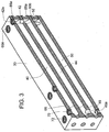
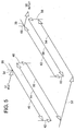
- the mass 30 is provided with a series of parallel and perpendicular bores that provide an elongated path for the flow of material through the mass 30. As may be seen in the cross-sectional drawing of FIG. 3 and the schematic rendition of FIG. 5 , material entering the structural mass 30 through the inlet bore 34 enters elongated bore 40.
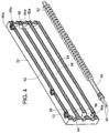
- the material flows down elongated bore 40 to its opposite end where it flows perpendicularly through vertical bore 42 to cross over to elongated bore 44. After flowing down elongated bore 44, the material again flows perpendicularly, vertically through bore 46 into elongated bore 50. The material flows through elongated bore 50, and, at the opposite end, flows perpendicularly through cross bore 52 and into elongated bore 54 (as may be seen in FIG. 4 ).
- the material flows through elongated bore 54, then perpendicularly vertically through bore 56 into and then through elongated bore 58, then perpendicularly vertically through bore 60 into and then through elongated bore 62, and then outward through the outlet fitting in outlet bore 38.
- the elongated bores or passages 40, 44, 50, 54, 58, 62 may be drilled into a solid block of a structural material such as aluminum.
- 6061 T6 Aluminum is utilized.
- the vertical bores 42, 46, 56, 60, the cross bore 52, the inlet bore 34 and outlet bore 38 may then be drilled to the appropriate depth in the block to properly construct the flow labyrinth.
- the labyrinth may be of any appropriate arrangement so long as the design provides the required heating properties.
- on the order of 15% - 30% of the mass 30 is open chemical flow paths, more preferably, approximately 22% is open flow paths.
- the apertures opening into the bores 42, 46, 56, 60 may be sealed with appropriately sized plugs 42a, 46a, 56a, 60a, and the inlet fitting 32 and outlet fitting 36 sealed to the inlet and outlet bores 34, 38 to complete the labyrinth.
- any appropriate method of sealing the same may be utilized.
- threads may be provided as shown and an appropriate gasket, o-ring or other seal provided.
- alternate inlet and outlet openings 66, 68 may be provided that open into the adjacent elongated bores 40, 62 from an alternate surface.
- the alternate inlet and outlet bores 66, 68 are provided in what is shown as the top surface of the mass 30 as opposed to the side surfaces to provide versatility in the design of the inlet and outlet configurations.
- one of each of the inlet and outlet bores 34, 66, 38, 68 may be sealed using an appropriate plug 70, 72 by any appropriate arrangement, as explained above.
- the preheater 22 is further provided with a plurality of elongated heater rods 74,76, 78, 80,82, 84 that are disposed directly in the elongated bores 40,44, 50,54, 58,62, respectively, of the structural mass 30.
- a pair of wires 85 is provided to a coupling 87 for each rod to provide power to heat the rods, as will be understood by those of skill in the art. In this way, the material flowing through the labyrinth of bores flows along and around the heating elements.
- a spiral flow path may be provided along the heater rods 74,76, 78,80, 82,84.
- This spiral flow path may be provided by any appropriate structure.
- the spiral flow path is provided by a coil 86, 88 ; 90,92, 94,96 that is sized such that it tightly contacts both the outer surfaces of the heater rods 74,76, 78,80, 82,84 and the inner surfaces of the elongated bores 40,44, 50,54, 58,62.
- a single such heater rod 80 and coil 92 is shown in FIG. 4 , although the remaining heater rod and coil combinations will be essentially the same.
- Plugs 86a, 88a, 90a, 92a, 94a, 96a are provided to seal the coils 86,88, 90,92, 94,96 within the bores 40,44, 50,54, 58,62.
- the coil 86, 88,90, 92,94, 96 forces the chemical material to uniformly flow between the heater rods 74,76, 78, 80, 82,84 and the bore 40,44, 50,54, 58,62, eliminating random flow that may result in inefficient heating.
- the preheater 22 provides every efficient heat transfer and very low backpressure development.
- the preheater may additionally include a temperature sensor 100 to assist in temperature control.
- the temperature sensor 100 is disposed in direct contact with the heater rod 74, i. e. the heater rod adjacent the outlet bore 34,66.
- a relatively small delta T is maintained between the surface of the element and the process temperature of the chemical material flowing through the preheater.
- the temperature sensor maybe fitted with a mass sleeve, which draws off any excess heat on the sensor during transitions and results in very stable temperature control.
- an over-temperature disk 102 may be provided along an outside surface of the mass 30 to cut power to the heater rods should an excessive external surface temperature be reached, i.e., over 210 F (98.9 0 C).
Landscapes
- Engineering & Computer Science (AREA)
- Physics & Mathematics (AREA)
- Thermal Sciences (AREA)
- Chemical & Material Sciences (AREA)
- Combustion & Propulsion (AREA)
- Mechanical Engineering (AREA)
- General Engineering & Computer Science (AREA)
- Pipe Accessories (AREA)
- Instantaneous Water Boilers, Portable Hot-Water Supply Apparatuses, And Control Of Portable Hot-Water Supply Apparatuses (AREA)
- Resistance Heating (AREA)
- Measuring Volume Flow (AREA)
Claims (16)
- Appareil de chauffage hybride pour chauffer des fluides, l'appareil de chauffage comprenant :une masse structurelle (30) comprenant une pluralité de passages allongés (40, 44, 50, 54, 58, 62), lesdits passages allongés étant accouplés pour fournir un trajet d'écoulement de chauffage allongé, de telle sorte que le trajet d'écoulement de chauffage allongé soit de l'ordre de 15 % à 30 % de la masse structurelle, ladite masse structurelle (30) comprenant en outre un alésage d'entrée (38) et un alésage de sortie (34) accouplés de façon fluidique au trajet d'écoulement de chauffage moyennant quoi,une pluralité de tiges de chauffage allongées (74, 76, 78, 80, 82, 84), lesdites tiges étant disposées à l'intérieur desdits passages allongés (40, 44, 50, 54, 58, 62) de telle sorte que le fluide introduit dans la masse structurelle (30) à travers l'alésage d'entrée (34) s'écoule à travers le trajet d'écoulement de chauffage allongé et hors de la masse structurelle (30) à travers l'alésage de sortie (38), le fluide s'écoulant entre les tiges de chauffage (74, 76, 78, 80, 82, 84) et les parois intérieures des passages allongés moyennant quoi ledit fluide est chauffé.
- Appareil de chauffage hybride selon la revendication 1, dans lequel la masse structurelle (30) comprend un bloc d'aluminium.
- Appareil de chauffage hybride selon la revendication 1 ou 2, dans lequel la masse structurelle (30) comprend une pluralité d'alésages forés (40, 42, 44, 46, 50, 52, 54, 56, 58, 60, 62), lesdits alésages forés formant ladite pluralité de passages allongés (40, 44, 50, 54, 58, 62) et formant ledit trajet d'écoulement de chauffage allongé.
- Appareil de chauffage hybride selon la revendication 3, dans lequel la pluralité d'alésages forés comprend une pluralité d'alésages forés dans une première direction (42, 46, 52, 56, 60) et une pluralité d'alésages forés dans une seconde direction (40, 44, 50, 54, 58, 62), ladite première direction étant sensiblement à angle droit par rapport à la seconde direction.
- Appareil de chauffage hybride selon l'une quelconque des revendications 1 à 4, dans lequel le trajet d'écoulement comprend en outre un trajet d'écoulement en spirale autour d'au moins l'une des tiges de chauffage allongées (74, 76, 78, 80, 82, 84) entre ladite tige de chauffage et la paroi intérieure d'au moins un passage allongé dans lequel ladite au moins une des tiges de chauffage allongées (74, 76, 78, 80, 82, 84) est disposée.
- Appareil de chauffage hybride selon la revendication 5, comprenant en outre un serpentin en spirale allongé (86, 88, 90, 92, 94, 96) disposé entre l'au moins une des tiges de chauffage allongées (74, 76, 78, 80, 82, 84) et l'au moins un passage allongé dans lequel ladite au moins une des tiges de chauffage allongées (74, 76, 78, 80, 82, 84) est disposée, ledit serpentin en spirale, ladite au moins une des tiges de chauffage allongées (74, 76, 78, 80, 82, 84) et ledit au moins un passage dans lequel ladite au moins une des tiges de chauffage allongées (74, 76, 78, 80, 82, 84) est disposée formant le trajet d'écoulement en spirale.
- Appareil de chauffage hybride selon l'une quelconque des revendications 1 à 6, comprenant en outre au moins un capteur de température (100).
- Appareil de chauffage hybride selon la revendication 7, dans lequel ledit au moins un capteur de température est disposé en contact direct avec au moins l'une desdites tiges de chauffage allongées (74, 76, 78, 80, 82, 84).
- Appareil de chauffage hybride selon les revendications 7 ou 8, comprenant en outre un manchon de masse, ledit manchon de masse étant disposé autour du capteur de température (100).
- Procédé de préchauffage d'un fluide, comprenant les étapes de :la fourniture d'énergie électrique à une pluralité de tiges de chauffage (74, 76, 78, 80, 82, 84) disposées à l'intérieur d'une pluralité de passages allongés (40, 44, 50, 54, 58, 62) formés dans une masse structurelle (30), la pluralité de passages allongés dans la masse structurelle (30) étant raccordés pour former un trajet d'écoulement de chauffage allongé, de telle sorte que le trajet d'écoulement de chauffage allongé soit de l'ordre de 15 % à 30 % de la masse structurelle,l'introduction du fluide dans la masse structurelle à travers une entrée (35) dans le trajet d'écoulement de chauffage allongé,le passage du fluide entre une pluralité de tiges de chauffage (74, 76, 78, 80, 82, 84) et les parois intérieures de la pluralité de passages allongés (40, 44, 50, 54, 58, 62) pour chauffer ledit fluide.
- Procédé selon la revendication 10, dans lequel l'étape du passage comprend l'étape du passage du fluide le long d'un trajet en spirale entre la pluralité de tiges de chauffage (74, 76, 78, 80, 82, 84) et les parois intérieures de la pluralité de passages allongés (40, 44, 50, 54, 58, 62).
- Procédé selon la revendication 10 ou 11, comprenant en outre l'étape de la surveillance de la température d'au moins un du fluide s'écoulant à travers le trajet d'écoulement ou au moins l'une des tiges de chauffage (74, 76, 78, 80, 82, 84).
- Procédé selon la revendication 12, dans lequel l'étape de la surveillance comprend l'utilisation d'un capteur de température (100) équipé d'un manchon de masse pour surveiller la température dudit au moins un fluide s'écoulant à travers le trajet d'écoulement ou au moins l'une des tiges de chauffage (74, 76, 78, 80, 82, 84).
- Procédé de fabrication d'un appareil de chauffage hybride préchauffant un fluide, comprenant :le forage d'une première pluralité d'alésages dans une première direction dans une masse structurelle pour former une pluralité de passages allongés (40, 44, 50, 54, 58, 62),le forage d'une seconde pluralité d'alésages dans une seconde direction pour raccorder la pluralité de passages allongés (40, 44, 50, 54, 58, 62), de telle sorte que les première et seconde pluralités d'alésages forment un trajet d'écoulement de chauffage allongé, qui est de l'ordre de 15 % à 30 % de la masse structurelle,le forage d'un alésage d'entrée (34) et d'un alésage de sortie (38) dans la masse structurelle, qui sont accouplés de façon fluidique au trajet d'écoulement de chauffage ;la disposition d'une pluralité de tiges de chauffage allongées (74, 76, 78, 80, 82, 84), à l'intérieur desdits passages allongés (40, 44, 50, 54, 58, 62) de telle sorte que, durant l'utilisation, un fluide introduit dans la masse structurelle (30) à travers l'alésage d'entrée (34) s'écoule à travers le trajet d'écoulement de chauffage allongé et hors de la masse structurelle (30) à travers l'alésage de sortie (38), pour que le fluide s'écoulant entre les tiges de chauffage (74, 76, 78, 80, 82, 84) et les parois intérieures des passages allongés soit chauffé.
- Procédé selon la revendication 14, comprenant en outre l'étape de la formation d'un trajet en spirale entre la pluralité de tiges de chauffage (74, 76, 78, 80, 82, 84) et les parois intérieures de la pluralité de passages allongés (40, 44, 50, 54, 58, 62).
- Procédé selon la revendication 15, dans lequel l'étape de la formation du trajet en spirale comprend l'étape de la disposition d'au moins un serpentin en spirale autour de la circonférence d'au moins l'une des tiges de chauffage (74, 76, 78, 80, 82, 84) de telle sorte que le serpentin soit en contact avec à la fois la tige de chauffage et le passage dans lequel elle est disposée.
Applications Claiming Priority (2)
| Application Number | Priority Date | Filing Date | Title |
|---|---|---|---|
| US54206204P | 2004-02-05 | 2004-02-05 | |
| PCT/US2005/002892 WO2005078355A1 (fr) | 2004-02-05 | 2005-02-01 | Appareil de chauffage hybride |
Publications (3)
| Publication Number | Publication Date |
|---|---|
| EP1718903A1 EP1718903A1 (fr) | 2006-11-08 |
| EP1718903A4 EP1718903A4 (fr) | 2007-10-10 |
| EP1718903B1 true EP1718903B1 (fr) | 2016-05-04 |
Family
ID=34860256
Family Applications (1)
| Application Number | Title | Priority Date | Filing Date |
|---|---|---|---|
| EP05712357.2A Expired - Lifetime EP1718903B1 (fr) | 2004-02-05 | 2005-02-01 | Appareil de chauffage hybride |
Country Status (8)
| Country | Link |
|---|---|
| US (2) | US7822326B2 (fr) |
| EP (1) | EP1718903B1 (fr) |
| KR (1) | KR101290066B1 (fr) |
| CN (1) | CN1918438B (fr) |
| BR (1) | BRPI0507452A (fr) |
| ES (1) | ES2584435T3 (fr) |
| RU (1) | RU2359181C2 (fr) |
| WO (1) | WO2005078355A1 (fr) |
Families Citing this family (35)
| Publication number | Priority date | Publication date | Assignee | Title |
|---|---|---|---|---|
| US7822326B2 (en) * | 2004-02-05 | 2010-10-26 | Graco Minnesota, Inc. | Hybrid heater |
| US8061263B1 (en) * | 2007-04-16 | 2011-11-22 | Richard W. Hein | Sensor head and brew cup for a beverage brewing device |
| US8071914B2 (en) * | 2007-12-26 | 2011-12-06 | Noboru Oshima | Heating apparatus |
| US20100046934A1 (en) * | 2008-08-19 | 2010-02-25 | Johnson Gregg C | High thermal transfer spiral flow heat exchanger |
| US8208800B2 (en) * | 2009-03-16 | 2012-06-26 | Hsien Mu Chiu | Potable water heating device |
| US20110002672A1 (en) * | 2009-07-06 | 2011-01-06 | Krapp Thomas E | Heater with improved airflow |
| US8396356B2 (en) * | 2009-07-24 | 2013-03-12 | Balboa Water Group, Inc. | Bathing installation heater assembly |
| DE102009038762B4 (de) * | 2009-08-27 | 2011-09-01 | Wiwa Wilhelm Wagner Gmbh & Co Kg | Wärmeübertrager |
| GB2493719A (en) * | 2011-08-15 | 2013-02-20 | Strix Ltd | Flow heater with temperature sensing and a heat sink |
| US8731386B2 (en) * | 2011-09-30 | 2014-05-20 | Borgwarner Beru Systems Gmbh | Electric heating device for heating fluids |
| FR2988818B1 (fr) * | 2012-03-28 | 2018-01-05 | Valeo Systemes Thermiques | Dispositif de chauffage electrique de fluide pour vehicule automobile et appareil de chauffage et/ou de climatisation associe |
| US9074819B2 (en) * | 2012-04-04 | 2015-07-07 | Gaumer Company, Inc. | High velocity fluid flow electric heater |
| JP5999631B2 (ja) * | 2012-04-20 | 2016-09-28 | サンデンホールディングス株式会社 | 加熱装置 |
| TWI471510B (zh) * | 2012-05-16 | 2015-02-01 | Yu Chen Lin | 電加熱裝置 |
| DE102012013342B4 (de) * | 2012-07-06 | 2025-12-31 | Stiebel Eltron Gmbh & Co. Kg | Heizblock |
| JP2014019287A (ja) * | 2012-07-18 | 2014-02-03 | Sanden Corp | 加熱装置及び加熱装置の製造方法 |
| US8755682B2 (en) * | 2012-07-18 | 2014-06-17 | Trebor International | Mixing header for fluid heater |
| JP5967760B2 (ja) * | 2012-07-18 | 2016-08-10 | サンデンホールディングス株式会社 | 加熱装置 |
| FR2996299B1 (fr) * | 2012-09-28 | 2018-07-13 | Valeo Systemes Thermiques | Dispositif de conditionnement thermique de fluide pour vehicule automobile et appareil de chauffage et/ou de climatisation correspondant |
| US9156046B2 (en) | 2013-01-25 | 2015-10-13 | Wagner Spray Tech Corporation | Plural component system heater |
| US10132525B2 (en) | 2013-03-15 | 2018-11-20 | Peter Klein | High thermal transfer flow-through heat exchanger |
| US9516971B2 (en) * | 2013-03-15 | 2016-12-13 | Peter Klein | High thermal transfer flow-through heat exchanger |
| BE1023731B1 (fr) * | 2013-04-03 | 2017-07-03 | Volante Nino | Dispositif de prechauffage de fluide notamment de fluide de refroidissement de moteur a combustion |
| US11083329B2 (en) * | 2014-07-03 | 2021-08-10 | B/E Aerospace, Inc. | Multi-phase circuit flow-through heater for aerospace beverage maker |
| US10524611B2 (en) | 2014-07-03 | 2020-01-07 | B/E Aerospace, Inc. | Multi-phase circuit flow-through heater for aerospace beverage maker |
| US11002465B2 (en) * | 2014-09-24 | 2021-05-11 | Bestway Inflatables & Materials Corp. | PTC heater |
| CN105258320A (zh) * | 2015-09-29 | 2016-01-20 | 成都健腾生物技术有限公司 | 一种流体电加热器 |
| US11255476B2 (en) * | 2015-10-29 | 2022-02-22 | Wagner Spray Tech Corporation | Internally heated modular fluid delivery system |
| US10921021B2 (en) * | 2016-03-23 | 2021-02-16 | Wwt Technischer Geraetebau Gmbh | Modular blood warmer |
| EP3366173B1 (fr) * | 2017-01-07 | 2023-02-22 | B/E Aerospace, Inc. | Dispositif de chauffage à circulation directe à circuit polyphasé pour appareil de préparation de boissons aérospatial |
| EP3703871B1 (fr) | 2017-10-31 | 2025-05-21 | Nordson Corporation | Système de distribution de matière liquide pourvu d'un dispositif de chauffage à manchon |
| WO2021191155A1 (fr) * | 2020-03-23 | 2021-09-30 | Kanthal Gmbh | Élément chauffant |
| USD1065459S1 (en) | 2022-09-27 | 2025-03-04 | Graco Minnesota Inc. | Spacer |
| USD1067369S1 (en) * | 2022-09-27 | 2025-03-18 | Graco Minnesota Inc. | Lubricant manifold |
| EP4667844A1 (fr) * | 2024-06-20 | 2025-12-24 | Durlescu, Anastasia | Échangeur de chaleur |
Citations (10)
| Publication number | Priority date | Publication date | Assignee | Title |
|---|---|---|---|---|
| US3968346A (en) | 1973-06-01 | 1976-07-06 | Cooksley Ralph D | Method and apparatus for electrically heating a fluid |
| US4334141A (en) | 1978-02-04 | 1982-06-08 | Firma Fritz Eichenauer | Combined electric water heating and vessel support plate for a beverage preparation device |
| US4395618A (en) | 1980-03-03 | 1983-07-26 | Emerson Electric Co. | Electric circulation heater for heating fluids such as oil |
| US4455475A (en) | 1981-09-14 | 1984-06-19 | Pier Francesco Talenti | Automatic device for quick heating of liquids, particularly water |
| US4501952A (en) | 1982-06-07 | 1985-02-26 | Graco Inc. | Electric fluid heater temperature control system providing precise control under varying conditions |
| US4723065A (en) | 1984-03-19 | 1988-02-02 | Howard E. Meyer | Electric automotive fuel heating system |
| US5325822A (en) | 1991-10-22 | 1994-07-05 | Fernandez Guillermo N | Electrtic, modular tankless fluids heater |
| DE10003042A1 (de) | 2000-01-25 | 2001-07-26 | Stiebel Eltron Gmbh & Co Kg | Elektrischer Durchlauferhitzer |
| DE20108117U1 (de) | 2001-05-09 | 2001-08-16 | Gerdes oHG, 21337 Lüneburg | Grundkörper, vorzugsweise als Komponente eines elektrischen Durchlauferhitzers |
| ES1048832U (es) | 1998-01-15 | 2001-10-01 | Gunther J W Schornstein | Bloque calefactor para maquinas de formacion de espuma de poliuretano. |
Family Cites Families (30)
| Publication number | Priority date | Publication date | Assignee | Title |
|---|---|---|---|---|
| US1744598A (en) | 1925-01-17 | 1930-01-21 | Nat Aniline & Chem Co Inc | Process and apparatus for heating |
| US2267264A (en) | 1940-05-14 | 1941-12-23 | James G Bland | Air conduit heater |
| US2775683A (en) * | 1954-07-16 | 1956-12-25 | Dole Refrigerating Co | Heat exchangers for vaporizing liquid refrigerant |
| US2802089A (en) | 1954-12-24 | 1957-08-06 | Beck Louis | Paint preheaters |
| US2866885A (en) | 1958-03-13 | 1958-12-30 | Roy E Mcilrath | Automatic electric heater |
| US3389538A (en) | 1965-08-09 | 1968-06-25 | Continental Oil Co | Sample vaporizing apparatus |
| US3584194A (en) | 1969-05-23 | 1971-06-08 | Aro Corp | Fluid heating techniques |
| US3898428A (en) * | 1974-03-07 | 1975-08-05 | Universal Oil Prod Co | Electric in line water heating apparatus |
| US4199675A (en) | 1977-06-23 | 1980-04-22 | Nordson Corporation | Electric fluid heater |
| DE2804784A1 (de) * | 1978-02-04 | 1979-08-09 | Eichenauer Fa Fritz | Elektrische widerstandsheizeinrichtung |
| US4369351A (en) | 1980-03-06 | 1983-01-18 | Cng Research Company | Method and apparatus for heating liquids and agglomerating slurries |
| US4434114A (en) * | 1982-02-04 | 1984-02-28 | Pennwalt Corporation | Production of wrinkle-free piezoelectric films by poling |
| US4465922A (en) | 1982-08-20 | 1984-08-14 | Nordson Corporation | Electric heater for heating high solids fluid coating materials |
| US5265318A (en) | 1991-06-02 | 1993-11-30 | Shero William K | Method for forming an in-line water heater having a spirally configured heat exchanger |
| GB2265445B (en) | 1992-03-27 | 1995-08-16 | Ralph Francis Bruce Andrews | Heating system |
| AU687581B2 (en) * | 1994-10-27 | 1998-02-26 | Watkins Manufacturing Corporation | Cartridge heater system |
| US6300395B1 (en) * | 1994-12-07 | 2001-10-09 | Nikon Parkerizing, Co., Ltd. | Aqueous hydrophilization treatment composition and method for aluminum-containing metal material |
| US5694515A (en) | 1995-01-09 | 1997-12-02 | The University Of Florida | Contact resistance-regulated storage heater for fluids |
| US5949958A (en) | 1995-06-07 | 1999-09-07 | Steris Corporation | Integral flash steam generator |
| US5724478A (en) * | 1996-05-14 | 1998-03-03 | Truheat Corporation | Liquid heater assembly |
| JP3557794B2 (ja) * | 1996-07-15 | 2004-08-25 | ソニー株式会社 | ディスクチェンジャ装置 |
| RU2119616C1 (ru) * | 1997-02-06 | 1998-09-27 | Акционерное общество закрытого типа "ДЕЛСОТ" | Электроводонагреватель |
| RU2133924C1 (ru) * | 1997-12-10 | 1999-07-27 | Донской Алексей Николаевич | Импульсный проточный электронагреватель |
| US6330395B1 (en) * | 1999-12-29 | 2001-12-11 | Chia-Hsiung Wu | Heating apparatus with safety sealing |
| DE10014021C2 (de) | 2000-03-22 | 2002-02-21 | Webasto Thermosysteme Gmbh | Heizsystem zum Beheizen des Innenraums eines Kraftfahrzeugs |
| BR0113999A (pt) * | 2000-09-21 | 2003-08-12 | Rohm & Haas | Processo para preparar uma dispersão polimérica aquosa nanocompósita de argila, dispersão nanocompósita aquosa, espessador, dispersante, aglutinante, composição de tinta flexográfica, verniz de sobre impressão, modificador de pó de cimento seco, semente polimérica nanocompósita de argila, composição polimérica nanocompósita de argila, e, método para preparar uma pluralidade de partìculas poliméricas nanocompósitas de argila ocas |
| US6389226B1 (en) * | 2001-05-09 | 2002-05-14 | Envirotech Systems Worldwide, Inc. | Modular tankless electronic water heater |
| US6944394B2 (en) * | 2002-01-22 | 2005-09-13 | Watlow Electric Manufacturing Company | Rapid response electric heat exchanger |
| US7822326B2 (en) * | 2004-02-05 | 2010-10-26 | Graco Minnesota, Inc. | Hybrid heater |
| US7046922B1 (en) * | 2005-03-15 | 2006-05-16 | Ion Tankless, Inc. | Modular tankless water heater |
-
2005
- 2005-02-01 US US10/588,202 patent/US7822326B2/en active Active
- 2005-02-01 BR BRPI0507452-5A patent/BRPI0507452A/pt not_active Application Discontinuation
- 2005-02-01 RU RU2006131783/06A patent/RU2359181C2/ru active
- 2005-02-01 KR KR1020067017128A patent/KR101290066B1/ko not_active Expired - Fee Related
- 2005-02-01 ES ES05712357.2T patent/ES2584435T3/es not_active Expired - Lifetime
- 2005-02-01 EP EP05712357.2A patent/EP1718903B1/fr not_active Expired - Lifetime
- 2005-02-01 CN CN2005800041551A patent/CN1918438B/zh not_active Expired - Fee Related
- 2005-02-01 WO PCT/US2005/002892 patent/WO2005078355A1/fr not_active Ceased
-
2010
- 2010-10-25 US US12/911,436 patent/US8249437B2/en not_active Expired - Fee Related
Patent Citations (10)
| Publication number | Priority date | Publication date | Assignee | Title |
|---|---|---|---|---|
| US3968346A (en) | 1973-06-01 | 1976-07-06 | Cooksley Ralph D | Method and apparatus for electrically heating a fluid |
| US4334141A (en) | 1978-02-04 | 1982-06-08 | Firma Fritz Eichenauer | Combined electric water heating and vessel support plate for a beverage preparation device |
| US4395618A (en) | 1980-03-03 | 1983-07-26 | Emerson Electric Co. | Electric circulation heater for heating fluids such as oil |
| US4455475A (en) | 1981-09-14 | 1984-06-19 | Pier Francesco Talenti | Automatic device for quick heating of liquids, particularly water |
| US4501952A (en) | 1982-06-07 | 1985-02-26 | Graco Inc. | Electric fluid heater temperature control system providing precise control under varying conditions |
| US4723065A (en) | 1984-03-19 | 1988-02-02 | Howard E. Meyer | Electric automotive fuel heating system |
| US5325822A (en) | 1991-10-22 | 1994-07-05 | Fernandez Guillermo N | Electrtic, modular tankless fluids heater |
| ES1048832U (es) | 1998-01-15 | 2001-10-01 | Gunther J W Schornstein | Bloque calefactor para maquinas de formacion de espuma de poliuretano. |
| DE10003042A1 (de) | 2000-01-25 | 2001-07-26 | Stiebel Eltron Gmbh & Co Kg | Elektrischer Durchlauferhitzer |
| DE20108117U1 (de) | 2001-05-09 | 2001-08-16 | Gerdes oHG, 21337 Lüneburg | Grundkörper, vorzugsweise als Komponente eines elektrischen Durchlauferhitzers |
Also Published As
| Publication number | Publication date |
|---|---|
| CN1918438B (zh) | 2011-11-30 |
| CN1918438A (zh) | 2007-02-21 |
| KR101290066B1 (ko) | 2013-07-26 |
| RU2006131783A (ru) | 2008-03-10 |
| KR20070006751A (ko) | 2007-01-11 |
| EP1718903A1 (fr) | 2006-11-08 |
| ES2584435T3 (es) | 2016-09-27 |
| BRPI0507452A (pt) | 2007-07-10 |
| WO2005078355A1 (fr) | 2005-08-25 |
| US20110038620A1 (en) | 2011-02-17 |
| EP1718903A4 (fr) | 2007-10-10 |
| RU2359181C2 (ru) | 2009-06-20 |
| US8249437B2 (en) | 2012-08-21 |
| US20070274697A1 (en) | 2007-11-29 |
| US7822326B2 (en) | 2010-10-26 |
Similar Documents
| Publication | Publication Date | Title |
|---|---|---|
| EP1718903B1 (fr) | Appareil de chauffage hybride | |
| CA1041079A (fr) | Echangeur de chaleur | |
| US6456785B1 (en) | Resistance heating element | |
| US8666238B2 (en) | Fluid preheater | |
| WO1998031045A2 (fr) | Appareil de chauffage de fluide ultra-pur a haute efficacite | |
| EP3676539B1 (fr) | Échangeur de chaleur pour chaudière, et tube d'échangeur de chaleur | |
| CN110195990B (zh) | 一种蒸汽温度控制阀门蒸汽发生器 | |
| CN106550502A (zh) | 加热体、加热组件、加热设备、加热装置及导热体 | |
| CN110736374B (zh) | 一种根据蓄热材料温度自主加热的蓄热器 | |
| CN111256504A (zh) | 一种根据蓄热温度控制阀门和电加热器的蓄热器 | |
| CN203687731U (zh) | 内置多级喷流管式翅片换热管 | |
| KR200176381Y1 (ko) | 소형 간이 온수보일러 | |
| CN110887391B (zh) | 一种根据蓄热材料温度控制加热的蓄热器 | |
| US4326897A (en) | Post weld heat treatment of shell and tube heat exchangers and apparatus | |
| JP2003240457A (ja) | 給湯用熱交換器 | |
| RU2145044C1 (ru) | Воздухонагреватель | |
| CN117006473B (zh) | 卧式导热油加热炉 | |
| CN217052092U (zh) | 一种黑火药油压加热板的改良结构 | |
| CN215724104U (zh) | 金属导热电加热装置 | |
| KR200366322Y1 (ko) | 순간 가열용 히팅 시스템 | |
| DK1255085T3 (da) | Varmeveksler med flere varmeviklinger og fremgangsmåde til fremstilling af denne | |
| JPH0224052Y2 (fr) | ||
| EP3412977B1 (fr) | Module radiant pour former un corps rayonnant | |
| RU34703U1 (ru) | Конвектор отопительный | |
| KR920004211Y1 (ko) | 조립식 온수 보일러 |
Legal Events
| Date | Code | Title | Description |
|---|---|---|---|
| PUAI | Public reference made under article 153(3) epc to a published international application that has entered the european phase |
Free format text: ORIGINAL CODE: 0009012 |
|
| 17P | Request for examination filed |
Effective date: 20060831 |
|
| AK | Designated contracting states |
Kind code of ref document: A1 Designated state(s): AT BE BG CH CY CZ DE DK EE ES FI FR GB GR HU IE IS IT LI LT LU MC NL PL PT RO SE SI SK TR |
|
| RAP1 | Party data changed (applicant data changed or rights of an application transferred) |
Owner name: GRACO MINNESOTA INC. |
|
| DAX | Request for extension of the european patent (deleted) | ||
| A4 | Supplementary search report drawn up and despatched |
Effective date: 20070911 |
|
| 17Q | First examination report despatched |
Effective date: 20090914 |
|
| TPAC | Observations filed by third parties |
Free format text: ORIGINAL CODE: EPIDOSNTIPA |
|
| GRAP | Despatch of communication of intention to grant a patent |
Free format text: ORIGINAL CODE: EPIDOSNIGR1 |
|
| INTG | Intention to grant announced |
Effective date: 20151201 |
|
| GRAS | Grant fee paid |
Free format text: ORIGINAL CODE: EPIDOSNIGR3 |
|
| GRAA | (expected) grant |
Free format text: ORIGINAL CODE: 0009210 |
|
| RIN1 | Information on inventor provided before grant (corrected) |
Inventor name: PRIEST, JEROME Inventor name: COMMETTE, DENIS, S. |
|
| AK | Designated contracting states |
Kind code of ref document: B1 Designated state(s): AT BE BG CH CY CZ DE DK EE ES FI FR GB GR HU IE IS IT LI LT LU MC NL PL PT RO SE SI SK TR |
|
| REG | Reference to a national code |
Ref country code: GB Ref legal event code: FG4D |
|
| REG | Reference to a national code |
Ref country code: CH Ref legal event code: EP |
|
| REG | Reference to a national code |
Ref country code: AT Ref legal event code: REF Ref document number: 797271 Country of ref document: AT Kind code of ref document: T Effective date: 20160515 |
|
| REG | Reference to a national code |
Ref country code: IE Ref legal event code: FG4D |
|
| REG | Reference to a national code |
Ref country code: DE Ref legal event code: R096 Ref document number: 602005049229 Country of ref document: DE |
|
| REG | Reference to a national code |
Ref country code: NL Ref legal event code: MP Effective date: 20160504 |
|
| REG | Reference to a national code |
Ref country code: LT Ref legal event code: MG4D |
|
| REG | Reference to a national code |
Ref country code: ES Ref legal event code: FG2A Ref document number: 2584435 Country of ref document: ES Kind code of ref document: T3 Effective date: 20160927 |
|
| PG25 | Lapsed in a contracting state [announced via postgrant information from national office to epo] |
Ref country code: LT Free format text: LAPSE BECAUSE OF FAILURE TO SUBMIT A TRANSLATION OF THE DESCRIPTION OR TO PAY THE FEE WITHIN THE PRESCRIBED TIME-LIMIT Effective date: 20160504 Ref country code: NL Free format text: LAPSE BECAUSE OF FAILURE TO SUBMIT A TRANSLATION OF THE DESCRIPTION OR TO PAY THE FEE WITHIN THE PRESCRIBED TIME-LIMIT Effective date: 20160504 Ref country code: FI Free format text: LAPSE BECAUSE OF FAILURE TO SUBMIT A TRANSLATION OF THE DESCRIPTION OR TO PAY THE FEE WITHIN THE PRESCRIBED TIME-LIMIT Effective date: 20160504 |
|
| REG | Reference to a national code |
Ref country code: AT Ref legal event code: MK05 Ref document number: 797271 Country of ref document: AT Kind code of ref document: T Effective date: 20160504 |
|
| PG25 | Lapsed in a contracting state [announced via postgrant information from national office to epo] |
Ref country code: GR Free format text: LAPSE BECAUSE OF FAILURE TO SUBMIT A TRANSLATION OF THE DESCRIPTION OR TO PAY THE FEE WITHIN THE PRESCRIBED TIME-LIMIT Effective date: 20160805 Ref country code: SE Free format text: LAPSE BECAUSE OF FAILURE TO SUBMIT A TRANSLATION OF THE DESCRIPTION OR TO PAY THE FEE WITHIN THE PRESCRIBED TIME-LIMIT Effective date: 20160504 Ref country code: PT Free format text: LAPSE BECAUSE OF FAILURE TO SUBMIT A TRANSLATION OF THE DESCRIPTION OR TO PAY THE FEE WITHIN THE PRESCRIBED TIME-LIMIT Effective date: 20160905 |
|
| PG25 | Lapsed in a contracting state [announced via postgrant information from national office to epo] |
Ref country code: EE Free format text: LAPSE BECAUSE OF FAILURE TO SUBMIT A TRANSLATION OF THE DESCRIPTION OR TO PAY THE FEE WITHIN THE PRESCRIBED TIME-LIMIT Effective date: 20160504 Ref country code: DK Free format text: LAPSE BECAUSE OF FAILURE TO SUBMIT A TRANSLATION OF THE DESCRIPTION OR TO PAY THE FEE WITHIN THE PRESCRIBED TIME-LIMIT Effective date: 20160504 Ref country code: CZ Free format text: LAPSE BECAUSE OF FAILURE TO SUBMIT A TRANSLATION OF THE DESCRIPTION OR TO PAY THE FEE WITHIN THE PRESCRIBED TIME-LIMIT Effective date: 20160504 Ref country code: SK Free format text: LAPSE BECAUSE OF FAILURE TO SUBMIT A TRANSLATION OF THE DESCRIPTION OR TO PAY THE FEE WITHIN THE PRESCRIBED TIME-LIMIT Effective date: 20160504 Ref country code: RO Free format text: LAPSE BECAUSE OF FAILURE TO SUBMIT A TRANSLATION OF THE DESCRIPTION OR TO PAY THE FEE WITHIN THE PRESCRIBED TIME-LIMIT Effective date: 20160504 |
|
| REG | Reference to a national code |
Ref country code: DE Ref legal event code: R026 Ref document number: 602005049229 Country of ref document: DE |
|
| PLBI | Opposition filed |
Free format text: ORIGINAL CODE: 0009260 |
|
| REG | Reference to a national code |
Ref country code: FR Ref legal event code: PLFP Year of fee payment: 13 |
|
| PG25 | Lapsed in a contracting state [announced via postgrant information from national office to epo] |
Ref country code: PL Free format text: LAPSE BECAUSE OF FAILURE TO SUBMIT A TRANSLATION OF THE DESCRIPTION OR TO PAY THE FEE WITHIN THE PRESCRIBED TIME-LIMIT Effective date: 20160504 Ref country code: AT Free format text: LAPSE BECAUSE OF FAILURE TO SUBMIT A TRANSLATION OF THE DESCRIPTION OR TO PAY THE FEE WITHIN THE PRESCRIBED TIME-LIMIT Effective date: 20160504 Ref country code: BE Free format text: LAPSE BECAUSE OF FAILURE TO SUBMIT A TRANSLATION OF THE DESCRIPTION OR TO PAY THE FEE WITHIN THE PRESCRIBED TIME-LIMIT Effective date: 20160504 |
|
| PLAX | Notice of opposition and request to file observation + time limit sent |
Free format text: ORIGINAL CODE: EPIDOSNOBS2 |
|
| 26 | Opposition filed |
Opponent name: GARRAF MAQUINARIA, S.A. Effective date: 20170203 |
|
| PG25 | Lapsed in a contracting state [announced via postgrant information from national office to epo] |
Ref country code: SI Free format text: LAPSE BECAUSE OF FAILURE TO SUBMIT A TRANSLATION OF THE DESCRIPTION OR TO PAY THE FEE WITHIN THE PRESCRIBED TIME-LIMIT Effective date: 20160504 |
|
| PLBB | Reply of patent proprietor to notice(s) of opposition received |
Free format text: ORIGINAL CODE: EPIDOSNOBS3 |
|
| PG25 | Lapsed in a contracting state [announced via postgrant information from national office to epo] |
Ref country code: MC Free format text: LAPSE BECAUSE OF FAILURE TO SUBMIT A TRANSLATION OF THE DESCRIPTION OR TO PAY THE FEE WITHIN THE PRESCRIBED TIME-LIMIT Effective date: 20160504 |
|
| REG | Reference to a national code |
Ref country code: CH Ref legal event code: PL |
|
| PG25 | Lapsed in a contracting state [announced via postgrant information from national office to epo] |
Ref country code: CH Free format text: LAPSE BECAUSE OF NON-PAYMENT OF DUE FEES Effective date: 20170228 Ref country code: LI Free format text: LAPSE BECAUSE OF NON-PAYMENT OF DUE FEES Effective date: 20170228 |
|
| REG | Reference to a national code |
Ref country code: IE Ref legal event code: MM4A |
|
| PG25 | Lapsed in a contracting state [announced via postgrant information from national office to epo] |
Ref country code: LU Free format text: LAPSE BECAUSE OF NON-PAYMENT OF DUE FEES Effective date: 20170201 |
|
| REG | Reference to a national code |
Ref country code: FR Ref legal event code: PLFP Year of fee payment: 14 |
|
| PG25 | Lapsed in a contracting state [announced via postgrant information from national office to epo] |
Ref country code: IE Free format text: LAPSE BECAUSE OF NON-PAYMENT OF DUE FEES Effective date: 20170201 |
|
| PLCK | Communication despatched that opposition was rejected |
Free format text: ORIGINAL CODE: EPIDOSNREJ1 |
|
| STAA | Information on the status of an ep patent application or granted ep patent |
Free format text: STATUS: THE PATENT HAS BEEN GRANTED |
|
| REG | Reference to a national code |
Ref country code: DE Ref legal event code: R100 Ref document number: 602005049229 Country of ref document: DE |
|
| PLAE | Information related to rejection of opposition modified |
Free format text: ORIGINAL CODE: 0009299REJO |
|
| PLAO | Information deleted related to despatch of communication that opposition is rejected |
Free format text: ORIGINAL CODE: EPIDOSDREJ1 |
|
| PLBJ | Opposition found inadmissible |
Free format text: ORIGINAL CODE: 0009275 |
|
| 26U | Opposition found inadmissible |
Opponent name: GARRAF MAQUINARIA, S.A. Effective date: 20180813 |
|
| D27O | Information related to the rejection of opposition deleted | ||
| PG25 | Lapsed in a contracting state [announced via postgrant information from national office to epo] |
Ref country code: HU Free format text: LAPSE BECAUSE OF FAILURE TO SUBMIT A TRANSLATION OF THE DESCRIPTION OR TO PAY THE FEE WITHIN THE PRESCRIBED TIME-LIMIT; INVALID AB INITIO Effective date: 20050201 |
|
| PG25 | Lapsed in a contracting state [announced via postgrant information from national office to epo] |
Ref country code: BG Free format text: LAPSE BECAUSE OF FAILURE TO SUBMIT A TRANSLATION OF THE DESCRIPTION OR TO PAY THE FEE WITHIN THE PRESCRIBED TIME-LIMIT Effective date: 20160504 |
|
| PG25 | Lapsed in a contracting state [announced via postgrant information from national office to epo] |
Ref country code: CY Free format text: LAPSE BECAUSE OF NON-PAYMENT OF DUE FEES Effective date: 20160504 |
|
| PG25 | Lapsed in a contracting state [announced via postgrant information from national office to epo] |
Ref country code: TR Free format text: LAPSE BECAUSE OF FAILURE TO SUBMIT A TRANSLATION OF THE DESCRIPTION OR TO PAY THE FEE WITHIN THE PRESCRIBED TIME-LIMIT Effective date: 20160504 |
|
| PG25 | Lapsed in a contracting state [announced via postgrant information from national office to epo] |
Ref country code: IS Free format text: LAPSE BECAUSE OF FAILURE TO SUBMIT A TRANSLATION OF THE DESCRIPTION OR TO PAY THE FEE WITHIN THE PRESCRIBED TIME-LIMIT Effective date: 20160904 |
|
| PGFP | Annual fee paid to national office [announced via postgrant information from national office to epo] |
Ref country code: GB Payment date: 20220225 Year of fee payment: 18 |
|
| PGFP | Annual fee paid to national office [announced via postgrant information from national office to epo] |
Ref country code: IT Payment date: 20220222 Year of fee payment: 18 Ref country code: FR Payment date: 20220223 Year of fee payment: 18 Ref country code: ES Payment date: 20220301 Year of fee payment: 18 |
|
| P01 | Opt-out of the competence of the unified patent court (upc) registered |
Effective date: 20230531 |
|
| GBPC | Gb: european patent ceased through non-payment of renewal fee |
Effective date: 20230201 |
|
| PG25 | Lapsed in a contracting state [announced via postgrant information from national office to epo] |
Ref country code: GB Free format text: LAPSE BECAUSE OF NON-PAYMENT OF DUE FEES Effective date: 20230201 |
|
| PG25 | Lapsed in a contracting state [announced via postgrant information from national office to epo] |
Ref country code: IT Free format text: LAPSE BECAUSE OF NON-PAYMENT OF DUE FEES Effective date: 20230201 Ref country code: GB Free format text: LAPSE BECAUSE OF NON-PAYMENT OF DUE FEES Effective date: 20230201 Ref country code: FR Free format text: LAPSE BECAUSE OF NON-PAYMENT OF DUE FEES Effective date: 20230228 |
|
| REG | Reference to a national code |
Ref country code: ES Ref legal event code: FD2A Effective date: 20240402 |
|
| PG25 | Lapsed in a contracting state [announced via postgrant information from national office to epo] |
Ref country code: ES Free format text: LAPSE BECAUSE OF NON-PAYMENT OF DUE FEES Effective date: 20230202 |
|
| PG25 | Lapsed in a contracting state [announced via postgrant information from national office to epo] |
Ref country code: ES Free format text: LAPSE BECAUSE OF NON-PAYMENT OF DUE FEES Effective date: 20230202 |
|
| PGFP | Annual fee paid to national office [announced via postgrant information from national office to epo] |
Ref country code: DE Payment date: 20240228 Year of fee payment: 20 |
|
| REG | Reference to a national code |
Ref country code: DE Ref legal event code: R071 Ref document number: 602005049229 Country of ref document: DE |