EP1719604A2 - Verfahren zur Beschichtung von Werkstücken - Google Patents
Verfahren zur Beschichtung von Werkstücken Download PDFInfo
- Publication number
- EP1719604A2 EP1719604A2 EP06004676A EP06004676A EP1719604A2 EP 1719604 A2 EP1719604 A2 EP 1719604A2 EP 06004676 A EP06004676 A EP 06004676A EP 06004676 A EP06004676 A EP 06004676A EP 1719604 A2 EP1719604 A2 EP 1719604A2
- Authority
- EP
- European Patent Office
- Prior art keywords
- film
- workpieces
- lifting
- press
- workpiece
- Prior art date
- Legal status (The legal status is an assumption and is not a legal conclusion. Google has not performed a legal analysis and makes no representation as to the accuracy of the status listed.)
- Granted
Links
Images

Classifications
-
- B—PERFORMING OPERATIONS; TRANSPORTING
- B29—WORKING OF PLASTICS; WORKING OF SUBSTANCES IN A PLASTIC STATE IN GENERAL
- B29C—SHAPING OR JOINING OF PLASTICS; SHAPING OF MATERIAL IN A PLASTIC STATE, NOT OTHERWISE PROVIDED FOR; AFTER-TREATMENT OF THE SHAPED PRODUCTS, e.g. REPAIRING
- B29C51/00—Shaping by thermoforming, i.e. shaping sheets or sheet like preforms after heating, e.g. shaping sheets in matched moulds or by deep-drawing; Apparatus therefor
- B29C51/26—Component parts, details or accessories; Auxiliary operations
- B29C51/42—Heating or cooling
- B29C51/421—Heating or cooling of preforms, specially adapted for thermoforming
-
- B—PERFORMING OPERATIONS; TRANSPORTING
- B29—WORKING OF PLASTICS; WORKING OF SUBSTANCES IN A PLASTIC STATE IN GENERAL
- B29C—SHAPING OR JOINING OF PLASTICS; SHAPING OF MATERIAL IN A PLASTIC STATE, NOT OTHERWISE PROVIDED FOR; AFTER-TREATMENT OF THE SHAPED PRODUCTS, e.g. REPAIRING
- B29C51/00—Shaping by thermoforming, i.e. shaping sheets or sheet like preforms after heating, e.g. shaping sheets in matched moulds or by deep-drawing; Apparatus therefor
- B29C51/04—Combined thermoforming and prestretching, e.g. biaxial stretching
- B29C51/06—Combined thermoforming and prestretching, e.g. biaxial stretching using pressure difference for prestretching
-
- B—PERFORMING OPERATIONS; TRANSPORTING
- B29—WORKING OF PLASTICS; WORKING OF SUBSTANCES IN A PLASTIC STATE IN GENERAL
- B29C—SHAPING OR JOINING OF PLASTICS; SHAPING OF MATERIAL IN A PLASTIC STATE, NOT OTHERWISE PROVIDED FOR; AFTER-TREATMENT OF THE SHAPED PRODUCTS, e.g. REPAIRING
- B29C51/00—Shaping by thermoforming, i.e. shaping sheets or sheet like preforms after heating, e.g. shaping sheets in matched moulds or by deep-drawing; Apparatus therefor
- B29C51/16—Lining or labelling
-
- B—PERFORMING OPERATIONS; TRANSPORTING
- B29—WORKING OF PLASTICS; WORKING OF SUBSTANCES IN A PLASTIC STATE IN GENERAL
- B29C—SHAPING OR JOINING OF PLASTICS; SHAPING OF MATERIAL IN A PLASTIC STATE, NOT OTHERWISE PROVIDED FOR; AFTER-TREATMENT OF THE SHAPED PRODUCTS, e.g. REPAIRING
- B29C63/00—Lining or sheathing, i.e. applying preformed layers or sheathings of plastics; Apparatus therefor
- B29C63/02—Lining or sheathing, i.e. applying preformed layers or sheathings of plastics; Apparatus therefor using sheet or web-like material
- B29C63/04—Lining or sheathing, i.e. applying preformed layers or sheathings of plastics; Apparatus therefor using sheet or web-like material by folding, winding, bending or the like
-
- B—PERFORMING OPERATIONS; TRANSPORTING
- B29—WORKING OF PLASTICS; WORKING OF SUBSTANCES IN A PLASTIC STATE IN GENERAL
- B29C—SHAPING OR JOINING OF PLASTICS; SHAPING OF MATERIAL IN A PLASTIC STATE, NOT OTHERWISE PROVIDED FOR; AFTER-TREATMENT OF THE SHAPED PRODUCTS, e.g. REPAIRING
- B29C2791/00—Shaping characteristics in general
- B29C2791/001—Shaping in several steps
-
- B—PERFORMING OPERATIONS; TRANSPORTING
- B29—WORKING OF PLASTICS; WORKING OF SUBSTANCES IN A PLASTIC STATE IN GENERAL
- B29C—SHAPING OR JOINING OF PLASTICS; SHAPING OF MATERIAL IN A PLASTIC STATE, NOT OTHERWISE PROVIDED FOR; AFTER-TREATMENT OF THE SHAPED PRODUCTS, e.g. REPAIRING
- B29C2791/00—Shaping characteristics in general
- B29C2791/004—Shaping under special conditions
- B29C2791/006—Using vacuum
-
- B—PERFORMING OPERATIONS; TRANSPORTING
- B29—WORKING OF PLASTICS; WORKING OF SUBSTANCES IN A PLASTIC STATE IN GENERAL
- B29C—SHAPING OR JOINING OF PLASTICS; SHAPING OF MATERIAL IN A PLASTIC STATE, NOT OTHERWISE PROVIDED FOR; AFTER-TREATMENT OF THE SHAPED PRODUCTS, e.g. REPAIRING
- B29C2791/00—Shaping characteristics in general
- B29C2791/004—Shaping under special conditions
- B29C2791/007—Using fluid under pressure
-
- B—PERFORMING OPERATIONS; TRANSPORTING
- B29—WORKING OF PLASTICS; WORKING OF SUBSTANCES IN A PLASTIC STATE IN GENERAL
- B29C—SHAPING OR JOINING OF PLASTICS; SHAPING OF MATERIAL IN A PLASTIC STATE, NOT OTHERWISE PROVIDED FOR; AFTER-TREATMENT OF THE SHAPED PRODUCTS, e.g. REPAIRING
- B29C51/00—Shaping by thermoforming, i.e. shaping sheets or sheet like preforms after heating, e.g. shaping sheets in matched moulds or by deep-drawing; Apparatus therefor
- B29C51/10—Forming by pressure difference, e.g. vacuum
-
- B—PERFORMING OPERATIONS; TRANSPORTING
- B29—WORKING OF PLASTICS; WORKING OF SUBSTANCES IN A PLASTIC STATE IN GENERAL
- B29C—SHAPING OR JOINING OF PLASTICS; SHAPING OF MATERIAL IN A PLASTIC STATE, NOT OTHERWISE PROVIDED FOR; AFTER-TREATMENT OF THE SHAPED PRODUCTS, e.g. REPAIRING
- B29C51/00—Shaping by thermoforming, i.e. shaping sheets or sheet like preforms after heating, e.g. shaping sheets in matched moulds or by deep-drawing; Apparatus therefor
- B29C51/16—Lining or labelling
- B29C51/162—Lining or labelling of deep containers or boxes
-
- B—PERFORMING OPERATIONS; TRANSPORTING
- B29—WORKING OF PLASTICS; WORKING OF SUBSTANCES IN A PLASTIC STATE IN GENERAL
- B29C—SHAPING OR JOINING OF PLASTICS; SHAPING OF MATERIAL IN A PLASTIC STATE, NOT OTHERWISE PROVIDED FOR; AFTER-TREATMENT OF THE SHAPED PRODUCTS, e.g. REPAIRING
- B29C51/00—Shaping by thermoforming, i.e. shaping sheets or sheet like preforms after heating, e.g. shaping sheets in matched moulds or by deep-drawing; Apparatus therefor
- B29C51/26—Component parts, details or accessories; Auxiliary operations
- B29C51/266—Auxiliary operations after the thermoforming operation
- B29C51/267—Two sheets being thermoformed in separate mould parts and joined together while still in the mould
Definitions
- the invention relates to a method for multi-sided coating of workpieces with film, in particular of furniture parts at the top and side surfaces, the workpieces - optionally by means of a pallet - are placed on a lower press part, then the film is placed above the workpieces in the press nip, the Press closed and the film is heated from above, wherein the film rests against the top of the workpieces and pressed after reaching a predetermined temperature range by top pressure and / or negative pressure not only on the top, but also on the side surfaces of the inserted workpieces and thus is glued.
- the main application of the invention is the coating of three-dimensional furniture parts to be coated not only on its front, but also on the peripheral side surfaces with a plastic film, a veneer or the like.
- the coating is carried out by applying heat and pressure in a press, usually several workpieces are fed simultaneously to the press in order to make optimum use of their capacity.
- the workpieces can be fed by means of a pallet of the press and on the lower part of the press, which usually has a special support system, are stored, whereupon they are coated together. After leaving the press, the workpieces are then separated by cutting out of the coherent film.
- the workpieces must be distanced from their base. This is done either by spacers that are inserted under each workpiece with a return to the outer contour or by support bolts in the form of lifting bolts that move into an upper position and thereby lift the workpieces. In both cases, the lower outer edge of the workpieces is released and the film can also be created there. Examples of support systems with lifting bolts are in the DE 197 18 561 and 198 36 219 described by the same applicant. Of course, you can also work with other support systems instead.
- the film is more capable of elastically compensating for the expansion differences between the workpiece top side and workpiece side surfaces without causing wrinkles.
- the present invention is therefore based on the object to improve the known coating method to the effect that even sensitive films, in particular high-gloss films, give a perfect coating.
- This object is achieved in that the film is at least partially lifted before gluing to the workpiece side surfaces briefly from the workpiece tops and held in suspension.
- the coating quality in particular in the case of high-gloss films, can be significantly improved by this measure.
- the reason for this might be as follows: The installation of the film on the upper side of the workpiece during heating causes a considerably lower film temperature than in those areas where the film has no contact with workpieces. This temperature difference in the film should be the trigger for the mentioned quality problems. It is significantly reduced by the lifting of the film from the workpiece tops, because the lifted foil areas can no longer give off heat to the workpiece and at the same time come closer to the heater.
- the desired lifting of the film can be realized constructively in different ways. Particularly expedient is the admission of the film by overpressure on the underside and / or negative pressure at the top. However, it is also within the scope of the invention to lift the film by mechanical forces, be it by raising from the edge of the film detecting holders or by tightening the film on a lying above the workpiece top level.
- the length of time during which the film remains lifted - in whole or in part - largely depends on the process parameters, in particular the temperature control and on the distance from which the film is still removed from the heater after lifting.
- the lower value for this period at least 3 seconds. It has been shown that this is often sufficient to realize the desired reheating of the previously cooled by the workpieces film areas.
- the heating of the film from above is expediently contactless by radiation. In this case, it is recommended that the film even in the raised state is still spaced from the top heater, because the radiator temperature otherwise leads to overheating of the film.
- the time for the film to lift off can also be varied. It is particularly favorable if the film is lifted off at the end of the heating phase and immediately thereafter the pressing against the workpiece upper side and side faces takes place.
- the film should be pressed down during the heating phase targeted to the workpiece top, so that there is a lower temperature than in the areas where the film has no contact with workpieces.
- FIG. 1 shows an overall view of the press for carrying out the method according to the invention.
- the press comprises a press frame 1, on which the press upper part 11 is fastened.
- the press base 12 is connected to the press frame 1 by two pressure cylinders 2a and 2b. By extending and retracting the impression cylinder 2a and 2b, the distance between the press base 12 and the press upper part 11 can be changed and the press base are pressed against the press upper part.
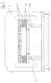
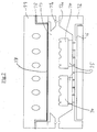
- Figures 2 to 5 respectively show the press upper part 11 and the press base 12 in an enlarged view. Both press parts form a cavity 13 in the retracted position for receiving the workpieces 14 to be coated.
- the workpieces 14 lie on support plates 15, which in each case spring back relative to the edge contour of the workpieces 14. As a result, the workpieces can be easily coated on their vertical side surfaces, in particular at their lower edges.
- the press upper part 11 essentially acts as a heating plate, which is heated electrically or otherwise. On its underside, it has a good heat-conducting, black radiating plate 17, which has almost the same temperature over the entire cross section.
- the upper press part 11 also contains a channel system 18 in order to pressurize the cavity 13 from above with negative pressure or overpressure.
- FIG. 2 shows the process stage in which the workpieces 14 have already been placed in the initially widely open press nip and the press upper part and press bottom part are then brought close together.
- the coating film is drawn into the press nip. Then the press is closed.
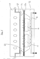
- FIG. 3 shows this state.
- the heating of the film takes place.
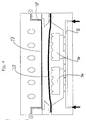
- the inventive method step according to FIG. 4 is initiated, namely a brief lifting of the film 20 from the workpieces 14. but the film does not come into contact with the heating surface 17.
- This lifting takes place expediently by overpressurization of the lower channel system 16, as indicated in FIG. It lies. but also in the context, instead or in addition to connect the lying above the film 20 cavity over the upper channel system 18 to negative pressure.
- the lifting of the film 20 from the workpieces 14 is suitably carried out during a period of about 5 seconds to about 10 seconds. This is sufficient that the very different temperatures between the film areas, which were previously in contact with the workpieces 14 and compensate for the adjacent film areas something. The temperature change between the two mentioned areas is therefore less abrupt, which has proved to be very favorable for the subsequent molding, especially in high-gloss films.
- FIG. 5 shows the following process stage. It may directly follow the lifting of the film 20 from the workpieces; but you can also leave the film 20 after the lifting operation briefly rest on the workpieces 14 before the molding process begins according to Figure 5.
- the actual molding process is carried out according to the known prior art, namely by strong overpressurization of the upper channel system 18 and / or negative pressure of the lower channel system 16, with the result that the film is pressed into the spaces between the workpieces 14 and the entire surface of the peripheral side surfaces the workpieces creates.
Landscapes
- Engineering & Computer Science (AREA)
- Mechanical Engineering (AREA)
- Manufacturing & Machinery (AREA)
- Blow-Moulding Or Thermoforming Of Plastics Or The Like (AREA)
- Laminated Bodies (AREA)
- Press Drives And Press Lines (AREA)
- Coating By Spraying Or Casting (AREA)
- Casting Or Compression Moulding Of Plastics Or The Like (AREA)
Abstract
Description
- Die Erfindung betrifft ein Verfahren zur mehrseitigen Beschichtung von Werkstücken mit Folie, insbesondere von Möbelteilen an deren Oberseite und Seitenflächen, wobei die Werkstücke - gegebenenfalls mittels einer Palette - auf einem unteren Pressenteil abgelegt werden, sodann die Folie oberhalb der Werkstücke in den Pressenspalt eingebracht, die Presse geschlossen und die Folie von oben beheizt wird, wobei die Folie an der Oberseite der Werkstücke anliegt und nach Erreichen eines vorgegebenen Temperaturbereiches durch oberseitigen Überdruck und/oder unterseitigen Unterdruck nicht nur an die Oberseite, sondern auch an die Seitenflächen der eingelegten Werkstücke gedrückt und damit verklebt wird.
- Hauptanwendungsfall der Erfindung ist das Beschichten dreidimensionaler Möbelteile, die nicht nur an ihrer Front, sondern auch an den umlaufenden Seitenflächen mit einer Kunststofffolie, einem Furnier oder dergleichen beschichtet werden sollen. Nachfolgend wird nur von einer Folie gesprochen, ohne dass damit eine Beschränkung der Erfindung gemeint ist. Das Beschichten erfolgt durch Anwendung von Wärme und Druck in einer Presse, wobei meist mehrere Werkstücke gleichzeitig der Presse zugeführt werden, um deren Kapazität optimal auszunutzen. Die Werkstücke können dabei mittels einer Palette der Presse zugeführt und auf dem unteren Pressenteil, das meist ein spezielles Auflagersystem aufweist, abgelegt werden, worauf sie gemeinsam beschichtet werden. Nach dem Verlassen der Presse werden die Werkstücke dann durch Ausschneiden aus der zusammenhängenden Folie vereinzelt.
- Damit die Kunststofffolie nicht nur an der Oberseite der Werkstücke, sondern auch an den davon zurückspringenden Seitenflächen, insbesondere an deren unteren Rand, gut angelegt und verbunden wird, müssen die Werkstücke von ihrer Unterlage distanziert werden. Dies geschieht entweder durch Distanzstücke, die unter jedem Werkstück mit Rücksprung gegenüber dessen Außenkontur einlegt werden oder durch Auflagerbolzen in Form von Hubbolzen, die in eine obere Position verfahren und dadurch die Werkstücke anheben. In beiden Fällen wird der untere Außenrand der Werkstücke frei und die Folie kann auch dort angelegt werden. Beispiele für Auflagersysteme mit Hubbolzen sind in der
DE 197 18 561 und198 36 219 der selben Anmelderin beschrieben. Selbstverständlich kann stattdessen aber auch mit anderen Auflagersystemen gearbeitet werden. - Damit die Beschichtung an der Oberseite, den Seitenflächen und den Kanten faltenfrei und plan von statten geht, empfiehlt es sich, dass die Folie während des Aufheizens nicht frei schwebt, sondern auf der Oberseite der Werkstücke aufliegt. Dadurch werden die Werkstücke an der Oberseite ebenfalls etwas erwärmt und der Temperaturunterschied zwischen Folie und Werkstück verringert. Die Folie ist dadurch eher in der Lage, die Dehnungsdifferenzen zwischen Werkstückoberseite und Werkstückseitenflächen elastisch auszugleichen, ohne dass Falten entstehen.
- Untersuchungen der Anmelderin haben aber nun gezeigt, dass die bisher bekannten Beschichtungsverfahren bei Verwendung von Hochglanzfolien problematisch sind. Diese Folien neigen dazu, an Glanz einzubüßen und/oder unbefriedigende Beschichtungsqualität an den Seitenflächen zu liefern.
- Der vorliegenden Erfindung liegt deshalb die Aufgabe zugrunde, die bekannten Beschichtungsverfahren dahingehend zu verbessern, dass auch empfindliche Folien, insbesondere Hochglanzfolien, eine einwandfreie Beschichtung ergeben.
- Diese Aufgabe wird erfindungsgemäß dadurch gelöst, dass die Folie zumindest teilweise vor dem Kleben an die Werkstück-Seitenflächen kurzzeitig von den Werkstückoberseiten abgehoben und in der Schwebe gehalten wird.
- Durch diese Maßnahme lässt sich überraschend die Beschichtungsqualität, insbesondere bei Hochglanzfolien, deutlich verbessern. Ursächlich hierfür dürfte nach Erkenntnissen der Anmelderin folgendes sein: Durch die Anlage der Folie an der Werkstückoberseite während des Aufheizens stellt sich dort eine deutlich niedrigere Folientemperatur ein als in denjenigen Bereichen, wo die Folie keinen Kontakt mit Werkstücken hat. Dieser Temperaturunterschied in der Folie dürfte der Auslöser für die genannten Qualitätsprobleme sein. Er wird durch das Abheben der Folie von den Werkstückoberseiten deutlich reduziert, weil die abgehobenen Folienbereiche keine Wärme mehr an das Werkstück abgeben können und gleichzeitig näher an der Heizung zu liegen kommen.
- Der gleiche Effekt ließe sich zwar auch dadurch erzielen, dass die Folie während des Aufheizens ständig von den Werkstücken distanziert gehalten wird; dann käme es aber beim Absenken der Folie auf die kalten Werkstücke zu einem Abschreckvorgang, der nach Untersuchungen der Anmelderin nachteilig für die Beschichtungsqualität ist. Demgegenüber führt das kurzzeitige Abheben der Folie zu dem Ergebnis, dass die Werkstücke vorgewärmt werden konnten, dass aber die Temperaturdifferenzen zwischen den Folienbereichen mit Werkstückkontakt und den Folienbereichen ohne Werkstückkontakt reduziert werden konnten. Man erhält dadurch eine glänzende Folienoberfläche bei gleichzeitig gut ausgeformten Seitenflächen.
- Das erwünschte Abheben der Folie kann konstruktiv auf unterschiedliche Weise realisiert werden. Besonders zweckmäßig ist die Beaufschlagung der Folie durch Überdruck an der Unterseite und/oder Unterdruck an der Oberseite. Es liegt aber auch im Rahmen der Erfindung, die Folie durch mechanische Kräfte abzuheben, sei es durch Hochfahren von den Folienrand erfassenden Haltern oder durch Straffen der Folie auf einem oberhalb der Werkstückoberseite liegenden Niveau.
- Die Zeitdauer, während der die Folie - ganz oder teilweise - abgehoben bleibt, hängt weitgehend von den Verfahrensparametern, insbesondere der Temperaturführung und von der Distanz ab, die die Folie nach dem Anheben noch von der Heizung entfernt ist. Zweckmäßig liegt der untere Wert für diese Zeitspanne bei zumindest 3 Sekunden. Es hat sich gezeigt, dass dies häufig schon ausreicht, um die gewünschte Nachheizung der zuvor von den Werkstücken gekühlten Folienbereiche zu realisieren.
- Es liegt auch im Rahmen der Erfindung, die Folie an der Unterseite mit Warmluft zu beaufschlagen und dadurch den Temperaturausgleich innerhalb der Folie zu beschleunigen.
- Die Beheizung der Folie von oben erfolgt zweckmäßig berührungslos durch Strahlung. In diesem Fall empfiehlt es sich, dass die Folie auch in angehobenem Zustand noch beabstandet zu der oberseitigen Heizung verläuft, weil die Strahlertemperatur andernfalls zu einer Überhitzung der Folie führt.
- Erfolgt die Beheizung der Folie jedoch durch Kontakt an einer Heizplatte, so muss diese Heizplatte selbstverständlich ebenfalls eine Hubbewegung durchführen, um das Abheben der Folie von den Werkstücken zu gestatten.
- Der Zeitpunkt für das Abheben der Folie kann ebenfalls variiert werden. Besonders günstig ist es, wenn die Folie am Ende der Heizphase abgehoben wird und unmittelbar danach das Anpressen an die Werkstück-Oberseite und - Seitenflächen erfolgt.
- Es liegt aber durchaus auch im Rahmen der Erfindung, nicht mit einem einzigen Abhebevorgang, sondern mit mehreren aufeinander folgenden Abhebevorgängen zu arbeiten, um von Anfang an die Ausbildung von Temperaturdifferenzen in der Folie zu bremsen.
- Grundsätzlich sollte die Folie aber während der Aufheizphase gezielt an die Werkstück-Oberseite herangedrückt werden, damit sie dort eine niedrigere Temperatur aufweist als in den Bereichen, wo die Folie keinen Kontakt mit Werkstücken hat.
- Weitere Merkmale und Vorteile der Erfindung ergeben sich aus der nachfolgenden Beschreibung eines Ausführungsbeispieles und aus der Zeichnung; dabei zeigt:
- Figur 1
- eine Gesamtansicht der Presse zur Durchführung des erfindungsgemäßen Verfahrens;
- Figur 2
- eine Ausschnittvergrößerung der den Pressspalt bildenden Pressenteile in einem Vertikalschnitt;
- Figur 3
- den gleichen Vertikalschnitt in einem zweiten Verfahrensstadium;
- Figur 4
- den gleichen Vertikalschnitt in einem dritten Verfahrensstadium und
- Figur 5
- den gleichen Vertikalschnitt in einem vierten Verfahrensstadium.
- In Figur 1 ist eine Gesamtansicht der Presse zur Durchführung des erfindungsgemäßen Verfahrens dargestellt. Die Presse umfasst einen Pressenrahmen 1, an dem das Pressenoberteil 11 befestigt ist. Das Pressenunterteil 12 ist durch zwei Druckzylinder 2a und 2b mit dem Pressenrahmen 1 verbunden. Durch Ein- und Ausfahren der Druckzylinder 2a und 2b kann der Abstand zwischen dem Pressenunterteil 12 und dem Pressenoberteil 11 verändert und das Pressenunterteil gegen das Pressenoberteil gepresst werden.
- Die Figuren 2 bis 5 zeigen jeweils das Pressenoberteil 11 und das Pressenunterteil 12 in vergrößerter Darstellung. Beide Pressenteile bilden in zusammengefahrener Stellung einen Hohlraum 13 zur Aufnahme der zu beschichtenden Werkstücke 14. Die Werkstücke 14 liegen auf Auflageplatten 15, die gegenüber der Randkontur der Werkstücke 14 jeweils zurückspringen. Dadurch können die Werkstücke auch an ihren vertikalen Seitenflächen, insbesondere an deren unteren Kanten problemlos beschichtet werden.
- Anstelle der gezeigten Auflageplatten 15 ist es auch möglich, die Werkstücke auf Hubbolzen zu lagern, die in eine obere Position verfahren werden können und dadurch die Werkstücke in die gezeigte Beschichtungsposition anheben. Solche Hubbolzen, die nicht von einem Werkstück bedeckt sind, bleiben hingegen in ihrer unteren Ruheposition, damit sie den Beschichtungsvorgang an den seitlichen Randflächen der Werkstücke nicht beeinträchtigen. Alternativ kann auch mit seitlich verstellbaren Auflagebolzen gearbeitet werden, die so verschoben werden können, dass sie jeweils unter einem Werkstück 14 zu liegen kommen.
- Desweiteren erkennt man in den Figuren 2 bis 5, dass das untere Pressenteil 12 jeweils ein Kanalsystem 16 aufweist, das den Hohlraum 13 mit einer nicht gezeigten Unterdruck- oder Überdruckquelle verbindet.
- Das Pressenoberteil 11 fungiert im wesentlichen als Heizplatte, die elektrisch oder auf andere Weise beheizt wird. An ihrer Unterseite weist sie eine gut Wärme leitende, schwarze Abstrahlplatte 17 auf, die über den gesamten Querschnitt nahezu die gleiche Temperatur aufweist.
- Schließlich enthält auch das obere Pressenteil 11 ein Kanalsystem 18, um den Hohlraum 13 von oben mit Unterdruck oder Überdruck beaufschlagen zu können.
- Figur 2 zeigt das Verfahrensstadium, bei dem die Werkstücke 14 bereits in den zunächst weit offenen Pressenspalt eingelegt worden sind und Pressenoberteil und Pressenunterteil anschließend nahe zusammengefahren sind. Vor dem Schließen wird die Beschichtungsfolie in den Pressspalt eingezogen. Anschließend wird die Presse geschlossen. Diesen Zustand zeigt Figur 3. Man erkennt dort die Beschichtungsfolie 20, die an ihren Rändern zwischen den am Pressenoberteil bzw. Pressenunterteil angeordneten Dichtungsrahmen 11a bzw. 12a gehalten wird. In ihrem mittleren Bereich liegt die Folie 20 hingegen schlaff auf den Werkstücken 14 auf. In diesem Verfahrensstadium erfolgt das Aufheizen der Folie. Um dabei einen definierten Wärmeübergang von der Folie auf die Werkstücke 14 herbeizuführen, empfiehlt es sich, die Folie entweder durch leichten Unterdruck im Kanalsystem 16 oder durch leichten Überdruck im Kanalsystem 18 an die Werkstücke anzudrücken.
- Wenn die Folie 20 die gewünschte Temperatur erreicht hat, so dass die an der Folienunterseite angebrachte Kleberschicht beginnt, reaktionsfähig zu werden oder vor Erreichen dieser Temperatur, wird der erfindungsgemäße Verfahrensschritt gemäß Figur 4 eingeleitet, nämlich ein kurzzeitiges Abheben der Folie 20 von den Werkstücken 14, wobei die Folie aber nicht in Kontakt mit der Heizfläche 17 kommt. Dieses Abheben erfolgt zweckmäßig durch Überdruckbeaufschlagung des unteren Kanalsystems 16, wie in Figur 4 angedeutet. Es liegt. aber auch im Rahmen, stattdessen oder zusätzlich den oberhalb der Folie 20 liegenden Hohlraum über das obere Kanalsystem 18 an Unterdruck anzuschließen.
- Das Abheben der Folie 20 von den Werkstücken 14 erfolgt zweckmäßig während einer Zeitspanne von etwa 5 Sekunden bis etwa 10 Sekunden. Dies reicht aus, dass sich die stark unterschiedlichen Temperaturen zwischen den Folienbereichen, die zuvor mit den Werkstücken 14 in Kontakt standen und den angrenzenden Folienbereichen etwas ausgleichen. Die Temperaturänderung zwischen den beiden genannten Bereichen erfolgt also weniger abrupt, was sich als sehr günstig für das anschließende Ausformen, speziell bei Hochglanzfolien, erwiesen hat.
- Figur 5 zeigt das folgende Verfahrensstadium. Es kann sich unmittelbar an das Abheben der Folie 20 von den Werkstücken anschließen; man kann die Folie 20 aber auch nach dem Abhebevorgang nochmal kurzzeitig auf den Werkstücken 14 ruhen lassen, bevor der Ausformvorgang gemäß Figur 5 beginnt. Der eigentliche Ausformvorgang erfolgt gemäß dem bekannten Stand der Technik, nämlich durch starke Überdruckbeaufschlagung des oberen Kanalsystems 18 und/oder Unterdruckbeaufschlagung des unteren Kanalsystems 16 mit der Folge, dass die Folie in die Zwischenräume zwischen den Werkstücken 14 hineingedrückt wird und sich vollflächig an die umlaufenden Seitenflächen der Werkstücke anlegt.
- Danach werden die Werkstücke mitsamt der sie verbindenden Folie aus der Presse entnommen und durch Ausschneiden aus der Folie in bekannter Weise vereinzelt.
- Soweit vorstehend von einem Anheben der Folie 20 von den Werkstücken 14 gesprochen worden ist, soll dies selbstverständlich auch die kinematische Umkehr einschließen, d.h., dass stattdessen die Folie ihre Position beibehalten kann und die Werkstücke abgesenkt werden. Auch eine Kombination beider Bewegungsvorgänge ist möglich. Entscheidend ist allein, dass der Kontakt zwischen der Folie und den Werkstückoberflächen gegen Ende der Aufheizphase kurzzeitig unterbrochen wird.
Claims (8)
- Verfahren zur mehrseitigen Beschichtung von Werkstücken (14) mit Folie (20), insbesondere von Möbelteilen an deren Oberseite und Seitenflächen, wobei die Werkstücke (14) auf einem unteren Pressenteil (12) abgelegt werden, sodann die Folie (20) oberhalb der Werkstücke (14) in den Pressenspalt eingebracht, die Presse geschlossen und die Folie von oben beheizt wird, wobei die Folie (20) nach Erreichen eines vorgegebenen Temperaturbereiches durch oberseitigen Überdruck und/oder unterseitigen Unterdruck nicht nur an die Oberseite, sondern auch an die Seitenflächen der eingelegten Werkstücke (14) gedrückt und damit verklebt wird
dadurch gekennzeichnet,
dass die Folie (20) zumindest teilweise vor dem Ankleben an die Werkstück-Seitenflächen kurzzeitig von den Werkstück-Oberseiten abgehoben und in der Schwebe gehalten wird. - Verfahren nach Anspruch 1,
dadurch gekennzeichnet,
dass das Abheben der Folie (20) durch unterseitigen Überdruck und/oder oberseitigen Unterdruck erzeugt wird. - Verfahren nach Anspruch 1,
dadurch gekennzeichnet,
dass das Abheben der Folie (20) während einer Zeit von zumindest 3 Sekunden erfolgt. - Verfahren nach Anspruch 1,
dadurch gekennzeichnet,
dass das Abheben der Folie während einer Zeit von etwa 4 Sekunden bis etwa 20 Sekunden, vorzugsweise etwa 5 Sekunden bis etwa 10 Sekunden erfolgt. - Verfahren nach Anspruch 1,
dadurch gekennzeichnet,
dass beim Abheben der Folie (20) unterseitig Warmluft eingeblasen wird. - Verfahren nach Anspruch 1,
dadurch gekennzeichnet,
dass die Folie (20) auch in abgehobenem Zustand noch beabstandet zu der oberseitigen Heizung verläuft. - Verfahren nach Anspruch 1,
dadurch gekennzeichnet,
dass das Abheben der Folie (20) unmittelbar vor dem Ankleben der Folie an die Werkstück-Oberseite und -Seitenflächen erfolgt. - Verfahren nach Anspruch 1,
dadurch gekennzeichnet,
dass die Folie (20) vor dem Abheben gezielt an die Werkstück-Oberseite gedrückt wird.
Priority Applications (1)
| Application Number | Priority Date | Filing Date | Title |
|---|---|---|---|
| PL06004676T PL1719604T3 (pl) | 2005-05-02 | 2006-03-08 | Sposób powlekania przedmiotów |
Applications Claiming Priority (1)
| Application Number | Priority Date | Filing Date | Title |
|---|---|---|---|
| DE102005020852A DE102005020852A1 (de) | 2005-05-02 | 2005-05-02 | Verfahren zur Beschichtung von Werkstücken |
Publications (3)
| Publication Number | Publication Date |
|---|---|
| EP1719604A2 true EP1719604A2 (de) | 2006-11-08 |
| EP1719604A3 EP1719604A3 (de) | 2011-01-19 |
| EP1719604B1 EP1719604B1 (de) | 2012-05-02 |
Family
ID=36616872
Family Applications (1)
| Application Number | Title | Priority Date | Filing Date |
|---|---|---|---|
| EP06004676A Expired - Lifetime EP1719604B1 (de) | 2005-05-02 | 2006-03-08 | Verfahren zur Beschichtung von Werkstücken |
Country Status (6)
| Country | Link |
|---|---|
| US (1) | US20060243372A1 (de) |
| EP (1) | EP1719604B1 (de) |
| AT (1) | ATE555891T1 (de) |
| AU (1) | AU2006201482A1 (de) |
| DE (1) | DE102005020852A1 (de) |
| PL (1) | PL1719604T3 (de) |
Cited By (3)
| Publication number | Priority date | Publication date | Assignee | Title |
|---|---|---|---|---|
| ITMO20100289A1 (it) * | 2010-10-18 | 2012-04-19 | Sarong Spa | Apparato di formatura |
| WO2016116118A1 (de) * | 2015-01-22 | 2016-07-28 | Liebherr-Hausgeräte Lienz Gmbh | Verfahren zum anbringen einer folie auf einen körper |
| EP3138682A4 (de) * | 2014-05-02 | 2017-04-12 | Asano Laboratories Co., Ltd. | Thermoformungsvorrichtung |
Families Citing this family (4)
| Publication number | Priority date | Publication date | Assignee | Title |
|---|---|---|---|---|
| US7625516B2 (en) * | 2007-08-31 | 2009-12-01 | C.I. Kasei Company, Limited | Method for manufacturing sheet molded body and insert molded body |
| EP2803470B1 (de) * | 2012-01-11 | 2017-03-08 | Scivax Corporation | Formverfahren |
| JP6179028B2 (ja) * | 2012-12-10 | 2017-08-16 | 株式会社フィルムマイスター | 内装パネル |
| DE102013101180A1 (de) * | 2013-02-06 | 2014-08-07 | Hebenstreit Gmbh | Backplattenanordnung für einen Waffelbackautomaten |
Family Cites Families (12)
| Publication number | Priority date | Publication date | Assignee | Title |
|---|---|---|---|---|
| US3770546A (en) * | 1972-01-07 | 1973-11-06 | Gen Motors Corp | Method of vinyl covering a refrigerator door panel |
| US4674972A (en) * | 1984-03-30 | 1987-06-23 | Wagner Curtis D | Apparatus for thermoforming plastic articles |
| US5201981A (en) * | 1991-08-16 | 1993-04-13 | Citadel Architectural Products, Inc. | Method of forming synthetic plastic film-projected building siding |
| US5562958A (en) * | 1991-10-15 | 1996-10-08 | The Dow Chemical Company | Packaging and wrapping film |
| US5989381A (en) * | 1992-07-30 | 1999-11-23 | C.I. Kasei Co., Ltd. | Method for adhesive bonding of an overlay film to an acrylic resin board |
| US5401355A (en) * | 1993-05-11 | 1995-03-28 | Stiller; Larry B. | Apparatus for manufacturing multiple colored pliable soft trim components using movable dies |
| US5410791A (en) * | 1993-07-01 | 1995-05-02 | General Electric Company | Fabrication chuck |
| US6699418B2 (en) * | 2001-02-23 | 2004-03-02 | Kuraray Co., Ltd. | Method for producing biaxially stretched film made of ethylene-vinyl alcohol copolymer |
| MXPA03008094A (es) * | 2001-03-09 | 2003-12-12 | Trespaphan Gmbh | Metodo para producir empaque biodegradable a partir de pelicula biaxialmente estirada. |
| GB0113403D0 (en) * | 2001-06-02 | 2001-07-25 | Bioprogress Tech Int Inc | Tablet enrobing |
| AU2002301963B1 (en) * | 2001-11-12 | 2003-05-01 | Manufacturing Evolutions (Nz) Limited | Thermoplastic sheathing of articles and molding process |
| US7605023B2 (en) * | 2002-08-29 | 2009-10-20 | Semiconductor Energy Laboratory Co., Ltd. | Manufacturing method for a semiconductor device and heat treatment method therefor |
-
2005
- 2005-05-02 DE DE102005020852A patent/DE102005020852A1/de not_active Withdrawn
-
2006
- 2006-03-08 EP EP06004676A patent/EP1719604B1/de not_active Expired - Lifetime
- 2006-03-08 AT AT06004676T patent/ATE555891T1/de active
- 2006-03-08 PL PL06004676T patent/PL1719604T3/pl unknown
- 2006-04-07 AU AU2006201482A patent/AU2006201482A1/en not_active Abandoned
- 2006-04-19 US US11/406,551 patent/US20060243372A1/en not_active Abandoned
Cited By (5)
| Publication number | Priority date | Publication date | Assignee | Title |
|---|---|---|---|---|
| ITMO20100289A1 (it) * | 2010-10-18 | 2012-04-19 | Sarong Spa | Apparato di formatura |
| WO2012052892A1 (en) * | 2010-10-18 | 2012-04-26 | Sarong Societa' Per Azioni | Forming apparatus |
| EP3138682A4 (de) * | 2014-05-02 | 2017-04-12 | Asano Laboratories Co., Ltd. | Thermoformungsvorrichtung |
| WO2016116118A1 (de) * | 2015-01-22 | 2016-07-28 | Liebherr-Hausgeräte Lienz Gmbh | Verfahren zum anbringen einer folie auf einen körper |
| US10661498B2 (en) | 2015-01-22 | 2020-05-26 | Liebherr-Hausgerate Lienz Gmbh | Method for applying a film onto a body |
Also Published As
| Publication number | Publication date |
|---|---|
| ATE555891T1 (de) | 2012-05-15 |
| DE102005020852A1 (de) | 2006-11-09 |
| PL1719604T3 (pl) | 2012-09-28 |
| AU2006201482A1 (en) | 2006-11-16 |
| US20060243372A1 (en) | 2006-11-02 |
| EP1719604A3 (de) | 2011-01-19 |
| EP1719604B1 (de) | 2012-05-02 |
Similar Documents
| Publication | Publication Date | Title |
|---|---|---|
| DE69815864T2 (de) | Verfahren und vorrichtung zum formen von holzfaserplatten | |
| WO2008104360A1 (de) | Verfahren zur umformung einer platine und kühlvorrichtung für eine platine | |
| EP1211051A2 (de) | Verfahren und Vorrichtung zur Herstellung einer präzisen Verbindung zwischen zwei Abdeckmaterialien für ein Verkleidungsteil | |
| EP3349963A1 (de) | Verfahren und vorrichtung zur herstellung eines mit einem schichtstoff kaschierten 3d-substrates | |
| DE2424085A1 (de) | Verfahren und vorrichtung zum herstellen einer verbundsicherheitsglasscheibe | |
| EP1719604B1 (de) | Verfahren zur Beschichtung von Werkstücken | |
| DE3827497C2 (de) | Vorrichtung zur Beschichtung von dreidimensionalen Körpern mit einer Folie | |
| DE4112607A1 (de) | Verfahren und vorrichtung zur beschichtung von profilierten oberflaechen plattenfoermiger werkstuecke | |
| EP1392480A2 (de) | Verfahren zur herstellung eines dreidimensional veformten körpers | |
| DE4206262A1 (de) | Verfahren zum verschweissen von halogenfreien thermoplastfolien | |
| DE69828687T2 (de) | Verfahren zur herstellung einer formgepresster türpanel aus holzverbundwerkstoff, daraus resultierender türpanel, und damit hergestelltes tür | |
| DE2546944A1 (de) | Plattenpresse zum herstellen von laminaten und aehnlichen formkoerpern | |
| DE19731561B4 (de) | Formwerkzeug zum Herstellen von Formteilen | |
| DE4310302C2 (de) | Verfahren und Membranformpresse zum Beschichten von dreidimensionalen Werkstücken | |
| CH386683A (de) | Verfahren zur Herstellung von sandwichartig zusammengesetzten gewölbten Formkörpern aus thermoplastischen Kunststoffen | |
| DE3935562A1 (de) | Membran-formpresse | |
| DE3103038C2 (de) | Vorrichtung zum Herstellen eines im wesentlichen aus zwei Halbschalen gebildeten Hohlkörpers | |
| DE102007012496B3 (de) | Etagenpresse für Formteile | |
| DE102007002997A1 (de) | Heißpresse zur Beschichtung von Werkstücken, insbesondere Möbelteilen, sowie Arbeitstisch hierfür | |
| DE10053764B4 (de) | Kurztaktpresse | |
| DE4307554C1 (de) | Sanitärgegenstand, wie Duschtasse oder Badewanne, sowie Verfahren und Vorrichtung zur Herstellung desselben | |
| DE3001872A1 (de) | Membranformpresse | |
| DE1906796A1 (de) | Vorrichtung zum Verbinden von Einsaetzen mit Huelsen mittels Pressbacken | |
| DE1528104A1 (de) | Vorrichtung und Verfahren zur Herstellung geschichteter Werkstuecke | |
| DE19927064B4 (de) | Verfahren und Vorrichtung zur Verformung von Blechen |
Legal Events
| Date | Code | Title | Description |
|---|---|---|---|
| PUAI | Public reference made under article 153(3) epc to a published international application that has entered the european phase |
Free format text: ORIGINAL CODE: 0009012 |
|
| AK | Designated contracting states |
Kind code of ref document: A2 Designated state(s): AT BE BG CH CY CZ DE DK EE ES FI FR GB GR HU IE IS IT LI LT LU LV MC NL PL PT RO SE SI SK TR |
|
| AX | Request for extension of the european patent |
Extension state: AL BA HR MK YU |
|
| RIC1 | Information provided on ipc code assigned before grant |
Ipc: B29C 51/42 20060101ALI20100810BHEP Ipc: B29C 51/10 20060101ALN20100810BHEP Ipc: B29C 63/02 20060101ALI20100810BHEP Ipc: B29C 51/06 20060101ALI20100810BHEP Ipc: B29C 51/16 20060101AFI20060707BHEP |
|
| PUAL | Search report despatched |
Free format text: ORIGINAL CODE: 0009013 |
|
| AK | Designated contracting states |
Kind code of ref document: A3 Designated state(s): AT BE BG CH CY CZ DE DK EE ES FI FR GB GR HU IE IS IT LI LT LU LV MC NL PL PT RO SE SI SK TR |
|
| AX | Request for extension of the european patent |
Extension state: AL BA HR MK YU |
|
| RIC1 | Information provided on ipc code assigned before grant |
Ipc: B29C 51/42 20060101ALI20101210BHEP Ipc: B29C 51/10 20060101ALN20101210BHEP Ipc: B29C 63/02 20060101ALI20101210BHEP Ipc: B29C 51/06 20060101ALI20101210BHEP Ipc: B27N 7/00 20060101ALI20101210BHEP Ipc: B29C 51/16 20060101AFI20060707BHEP Ipc: B29C 69/00 20060101ALN20101210BHEP |
|
| 17P | Request for examination filed |
Effective date: 20110408 |
|
| AKX | Designation fees paid |
Designated state(s): AT BE BG CH CY CZ DE DK EE ES FI FR GB GR HU IE IS IT LI LT LU LV MC NL PL PT RO SE SI SK TR |
|
| RIC1 | Information provided on ipc code assigned before grant |
Ipc: B29C 63/04 20060101ALI20110930BHEP Ipc: B29C 63/02 20060101ALI20110930BHEP Ipc: B29C 51/42 20060101ALI20110930BHEP Ipc: B29C 69/00 20060101ALN20110930BHEP Ipc: B29C 51/10 20060101ALN20110930BHEP Ipc: B29C 51/06 20060101ALI20110930BHEP Ipc: B29C 51/16 20060101AFI20110930BHEP Ipc: B27N 7/00 20060101ALI20110930BHEP |
|
| GRAP | Despatch of communication of intention to grant a patent |
Free format text: ORIGINAL CODE: EPIDOSNIGR1 |
|
| RIC1 | Information provided on ipc code assigned before grant |
Ipc: B29C 51/06 20060101ALI20111130BHEP Ipc: B29C 51/16 20060101AFI20111130BHEP Ipc: B29C 63/02 20060101ALI20111130BHEP Ipc: B29C 51/42 20060101ALI20111130BHEP Ipc: B29C 63/04 20060101ALI20111130BHEP Ipc: B27N 7/00 20060101ALI20111130BHEP Ipc: B29C 51/10 20060101ALN20111130BHEP Ipc: B29C 69/00 20060101ALN20111130BHEP |
|
| GRAS | Grant fee paid |
Free format text: ORIGINAL CODE: EPIDOSNIGR3 |
|
| GRAA | (expected) grant |
Free format text: ORIGINAL CODE: 0009210 |
|
| AK | Designated contracting states |
Kind code of ref document: B1 Designated state(s): AT BE BG CH CY CZ DE DK EE ES FI FR GB GR HU IE IS IT LI LT LU LV MC NL PL PT RO SE SI SK TR |
|
| REG | Reference to a national code |
Ref country code: GB Ref legal event code: FG4D Free format text: NOT ENGLISH |
|
| REG | Reference to a national code |
Ref country code: AT Ref legal event code: REF Ref document number: 555891 Country of ref document: AT Kind code of ref document: T Effective date: 20120515 Ref country code: CH Ref legal event code: EP |
|
| REG | Reference to a national code |
Ref country code: IE Ref legal event code: FG4D Free format text: LANGUAGE OF EP DOCUMENT: GERMAN |
|
| REG | Reference to a national code |
Ref country code: DE Ref legal event code: R096 Ref document number: 502006011370 Country of ref document: DE Effective date: 20120628 |
|
| REG | Reference to a national code |
Ref country code: NL Ref legal event code: VDEP Effective date: 20120502 |
|
| REG | Reference to a national code |
Ref country code: PL Ref legal event code: T3 |
|
| REG | Reference to a national code |
Ref country code: LT Ref legal event code: MG4D Effective date: 20120502 |
|
| PG25 | Lapsed in a contracting state [announced via postgrant information from national office to epo] |
Ref country code: LT Free format text: LAPSE BECAUSE OF FAILURE TO SUBMIT A TRANSLATION OF THE DESCRIPTION OR TO PAY THE FEE WITHIN THE PRESCRIBED TIME-LIMIT Effective date: 20120502 Ref country code: CY Free format text: LAPSE BECAUSE OF FAILURE TO SUBMIT A TRANSLATION OF THE DESCRIPTION OR TO PAY THE FEE WITHIN THE PRESCRIBED TIME-LIMIT Effective date: 20120502 Ref country code: SE Free format text: LAPSE BECAUSE OF FAILURE TO SUBMIT A TRANSLATION OF THE DESCRIPTION OR TO PAY THE FEE WITHIN THE PRESCRIBED TIME-LIMIT Effective date: 20120502 Ref country code: FI Free format text: LAPSE BECAUSE OF FAILURE TO SUBMIT A TRANSLATION OF THE DESCRIPTION OR TO PAY THE FEE WITHIN THE PRESCRIBED TIME-LIMIT Effective date: 20120502 Ref country code: IS Free format text: LAPSE BECAUSE OF FAILURE TO SUBMIT A TRANSLATION OF THE DESCRIPTION OR TO PAY THE FEE WITHIN THE PRESCRIBED TIME-LIMIT Effective date: 20120902 |
|
| PG25 | Lapsed in a contracting state [announced via postgrant information from national office to epo] |
Ref country code: SI Free format text: LAPSE BECAUSE OF FAILURE TO SUBMIT A TRANSLATION OF THE DESCRIPTION OR TO PAY THE FEE WITHIN THE PRESCRIBED TIME-LIMIT Effective date: 20120502 Ref country code: PT Free format text: LAPSE BECAUSE OF FAILURE TO SUBMIT A TRANSLATION OF THE DESCRIPTION OR TO PAY THE FEE WITHIN THE PRESCRIBED TIME-LIMIT Effective date: 20120903 Ref country code: GR Free format text: LAPSE BECAUSE OF FAILURE TO SUBMIT A TRANSLATION OF THE DESCRIPTION OR TO PAY THE FEE WITHIN THE PRESCRIBED TIME-LIMIT Effective date: 20120803 Ref country code: LV Free format text: LAPSE BECAUSE OF FAILURE TO SUBMIT A TRANSLATION OF THE DESCRIPTION OR TO PAY THE FEE WITHIN THE PRESCRIBED TIME-LIMIT Effective date: 20120502 |
|
| PG25 | Lapsed in a contracting state [announced via postgrant information from national office to epo] |
Ref country code: SK Free format text: LAPSE BECAUSE OF FAILURE TO SUBMIT A TRANSLATION OF THE DESCRIPTION OR TO PAY THE FEE WITHIN THE PRESCRIBED TIME-LIMIT Effective date: 20120502 Ref country code: CZ Free format text: LAPSE BECAUSE OF FAILURE TO SUBMIT A TRANSLATION OF THE DESCRIPTION OR TO PAY THE FEE WITHIN THE PRESCRIBED TIME-LIMIT Effective date: 20120502 Ref country code: EE Free format text: LAPSE BECAUSE OF FAILURE TO SUBMIT A TRANSLATION OF THE DESCRIPTION OR TO PAY THE FEE WITHIN THE PRESCRIBED TIME-LIMIT Effective date: 20120502 Ref country code: RO Free format text: LAPSE BECAUSE OF FAILURE TO SUBMIT A TRANSLATION OF THE DESCRIPTION OR TO PAY THE FEE WITHIN THE PRESCRIBED TIME-LIMIT Effective date: 20120502 Ref country code: NL Free format text: LAPSE BECAUSE OF FAILURE TO SUBMIT A TRANSLATION OF THE DESCRIPTION OR TO PAY THE FEE WITHIN THE PRESCRIBED TIME-LIMIT Effective date: 20120502 Ref country code: DK Free format text: LAPSE BECAUSE OF FAILURE TO SUBMIT A TRANSLATION OF THE DESCRIPTION OR TO PAY THE FEE WITHIN THE PRESCRIBED TIME-LIMIT Effective date: 20120502 |
|
| PLBE | No opposition filed within time limit |
Free format text: ORIGINAL CODE: 0009261 |
|
| STAA | Information on the status of an ep patent application or granted ep patent |
Free format text: STATUS: NO OPPOSITION FILED WITHIN TIME LIMIT |
|
| 26N | No opposition filed |
Effective date: 20130205 |
|
| PG25 | Lapsed in a contracting state [announced via postgrant information from national office to epo] |
Ref country code: ES Free format text: LAPSE BECAUSE OF FAILURE TO SUBMIT A TRANSLATION OF THE DESCRIPTION OR TO PAY THE FEE WITHIN THE PRESCRIBED TIME-LIMIT Effective date: 20120813 |
|
| REG | Reference to a national code |
Ref country code: DE Ref legal event code: R097 Ref document number: 502006011370 Country of ref document: DE Effective date: 20130205 |
|
| PG25 | Lapsed in a contracting state [announced via postgrant information from national office to epo] |
Ref country code: BG Free format text: LAPSE BECAUSE OF FAILURE TO SUBMIT A TRANSLATION OF THE DESCRIPTION OR TO PAY THE FEE WITHIN THE PRESCRIBED TIME-LIMIT Effective date: 20120802 |
|
| BERE | Be: lapsed |
Owner name: ROBERT BURKLE G.M.B.H. Effective date: 20130331 |
|
| PG25 | Lapsed in a contracting state [announced via postgrant information from national office to epo] |
Ref country code: MC Free format text: LAPSE BECAUSE OF NON-PAYMENT OF DUE FEES Effective date: 20130331 |
|
| REG | Reference to a national code |
Ref country code: CH Ref legal event code: PL |
|
| REG | Reference to a national code |
Ref country code: FR Ref legal event code: ST Effective date: 20131129 |
|
| REG | Reference to a national code |
Ref country code: IE Ref legal event code: MM4A |
|
| PG25 | Lapsed in a contracting state [announced via postgrant information from national office to epo] |
Ref country code: IE Free format text: LAPSE BECAUSE OF NON-PAYMENT OF DUE FEES Effective date: 20130308 Ref country code: FR Free format text: LAPSE BECAUSE OF NON-PAYMENT OF DUE FEES Effective date: 20130402 Ref country code: BE Free format text: LAPSE BECAUSE OF NON-PAYMENT OF DUE FEES Effective date: 20130331 Ref country code: LI Free format text: LAPSE BECAUSE OF NON-PAYMENT OF DUE FEES Effective date: 20130331 Ref country code: CH Free format text: LAPSE BECAUSE OF NON-PAYMENT OF DUE FEES Effective date: 20130331 |
|
| PG25 | Lapsed in a contracting state [announced via postgrant information from national office to epo] |
Ref country code: LU Free format text: LAPSE BECAUSE OF NON-PAYMENT OF DUE FEES Effective date: 20130308 Ref country code: HU Free format text: LAPSE BECAUSE OF FAILURE TO SUBMIT A TRANSLATION OF THE DESCRIPTION OR TO PAY THE FEE WITHIN THE PRESCRIBED TIME-LIMIT; INVALID AB INITIO Effective date: 20060308 |
|
| PGFP | Annual fee paid to national office [announced via postgrant information from national office to epo] |
Ref country code: AT Payment date: 20160318 Year of fee payment: 11 |
|
| REG | Reference to a national code |
Ref country code: AT Ref legal event code: MM01 Ref document number: 555891 Country of ref document: AT Kind code of ref document: T Effective date: 20170308 |
|
| PG25 | Lapsed in a contracting state [announced via postgrant information from national office to epo] |
Ref country code: AT Free format text: LAPSE BECAUSE OF NON-PAYMENT OF DUE FEES Effective date: 20170308 |
|
| PGFP | Annual fee paid to national office [announced via postgrant information from national office to epo] |
Ref country code: TR Payment date: 20230306 Year of fee payment: 18 Ref country code: PL Payment date: 20230227 Year of fee payment: 18 Ref country code: GB Payment date: 20230323 Year of fee payment: 18 Ref country code: DE Payment date: 20230217 Year of fee payment: 18 |
|
| P01 | Opt-out of the competence of the unified patent court (upc) registered |
Effective date: 20230509 |
|
| PGFP | Annual fee paid to national office [announced via postgrant information from national office to epo] |
Ref country code: IT Payment date: 20230331 Year of fee payment: 18 |
|
| REG | Reference to a national code |
Ref country code: DE Ref legal event code: R119 Ref document number: 502006011370 Country of ref document: DE |
|
| GBPC | Gb: european patent ceased through non-payment of renewal fee |
Effective date: 20240308 |
|
| PG25 | Lapsed in a contracting state [announced via postgrant information from national office to epo] |
Ref country code: DE Free format text: LAPSE BECAUSE OF NON-PAYMENT OF DUE FEES Effective date: 20241001 |
|
| PG25 | Lapsed in a contracting state [announced via postgrant information from national office to epo] |
Ref country code: GB Free format text: LAPSE BECAUSE OF NON-PAYMENT OF DUE FEES Effective date: 20240308 |
|
| PG25 | Lapsed in a contracting state [announced via postgrant information from national office to epo] |
Ref country code: GB Free format text: LAPSE BECAUSE OF NON-PAYMENT OF DUE FEES Effective date: 20240308 Ref country code: DE Free format text: LAPSE BECAUSE OF NON-PAYMENT OF DUE FEES Effective date: 20241001 |
|
| PG25 | Lapsed in a contracting state [announced via postgrant information from national office to epo] |
Ref country code: IT Free format text: LAPSE BECAUSE OF NON-PAYMENT OF DUE FEES Effective date: 20240308 |
|
| PG25 | Lapsed in a contracting state [announced via postgrant information from national office to epo] |
Ref country code: PL Free format text: LAPSE BECAUSE OF NON-PAYMENT OF DUE FEES Effective date: 20240308 |
|
| PG25 | Lapsed in a contracting state [announced via postgrant information from national office to epo] |
Ref country code: TR Free format text: LAPSE BECAUSE OF NON-PAYMENT OF DUE FEES Effective date: 20240308 |