EP1719892A2 - Dispositif et méthode de commande de moteur pour véhicule du type monté à califourchon - Google Patents
Dispositif et méthode de commande de moteur pour véhicule du type monté à califourchon Download PDFInfo
- Publication number
- EP1719892A2 EP1719892A2 EP06009077A EP06009077A EP1719892A2 EP 1719892 A2 EP1719892 A2 EP 1719892A2 EP 06009077 A EP06009077 A EP 06009077A EP 06009077 A EP06009077 A EP 06009077A EP 1719892 A2 EP1719892 A2 EP 1719892A2
- Authority
- EP
- European Patent Office
- Prior art keywords
- engine
- rotational speed
- target rotational
- failure
- speed
- Prior art date
- Legal status (The legal status is an assumption and is not a legal conclusion. Google has not performed a legal analysis and makes no representation as to the accuracy of the status listed.)
- Granted
Links
Images

Classifications
-
- F—MECHANICAL ENGINEERING; LIGHTING; HEATING; WEAPONS; BLASTING
- F02—COMBUSTION ENGINES; HOT-GAS OR COMBUSTION-PRODUCT ENGINE PLANTS
- F02D—CONTROLLING COMBUSTION ENGINES
- F02D31/00—Use of speed-sensing governors to control combustion engines, not otherwise provided for
- F02D31/001—Electric control of rotation speed
- F02D31/007—Electric control of rotation speed controlling fuel supply
- F02D31/009—Electric control of rotation speed controlling fuel supply for maximum speed control
-
- F—MECHANICAL ENGINEERING; LIGHTING; HEATING; WEAPONS; BLASTING
- F02—COMBUSTION ENGINES; HOT-GAS OR COMBUSTION-PRODUCT ENGINE PLANTS
- F02D—CONTROLLING COMBUSTION ENGINES
- F02D11/00—Arrangements for, or adaptations to, non-automatic engine control initiation means, e.g. operator initiated
- F02D11/06—Arrangements for, or adaptations to, non-automatic engine control initiation means, e.g. operator initiated characterised by non-mechanical control linkages, e.g. fluid control linkages or by control linkages with power drive or assistance
- F02D11/10—Arrangements for, or adaptations to, non-automatic engine control initiation means, e.g. operator initiated characterised by non-mechanical control linkages, e.g. fluid control linkages or by control linkages with power drive or assistance of the electric type
- F02D11/107—Safety-related aspects
-
- F—MECHANICAL ENGINEERING; LIGHTING; HEATING; WEAPONS; BLASTING
- F02—COMBUSTION ENGINES; HOT-GAS OR COMBUSTION-PRODUCT ENGINE PLANTS
- F02D—CONTROLLING COMBUSTION ENGINES
- F02D37/00—Non-electrical conjoint control of two or more functions of engines, not otherwise provided for
- F02D37/02—Non-electrical conjoint control of two or more functions of engines, not otherwise provided for one of the functions being ignition
-
- F—MECHANICAL ENGINEERING; LIGHTING; HEATING; WEAPONS; BLASTING
- F02—COMBUSTION ENGINES; HOT-GAS OR COMBUSTION-PRODUCT ENGINE PLANTS
- F02D—CONTROLLING COMBUSTION ENGINES
- F02D41/00—Electrical control of supply of combustible mixture or its constituents
- F02D41/22—Safety or indicating devices for abnormal conditions
-
- F—MECHANICAL ENGINEERING; LIGHTING; HEATING; WEAPONS; BLASTING
- F02—COMBUSTION ENGINES; HOT-GAS OR COMBUSTION-PRODUCT ENGINE PLANTS
- F02P—IGNITION, OTHER THAN COMPRESSION IGNITION, FOR INTERNAL-COMBUSTION ENGINES; TESTING OF IGNITION TIMING IN COMPRESSION-IGNITION ENGINES
- F02P5/00—Advancing or retarding ignition; Control therefor
- F02P5/04—Advancing or retarding ignition; Control therefor automatically, as a function of the working conditions of the engine or vehicle or of the atmospheric conditions
- F02P5/145—Advancing or retarding ignition; Control therefor automatically, as a function of the working conditions of the engine or vehicle or of the atmospheric conditions using electrical means
- F02P5/15—Digital data processing
- F02P5/1502—Digital data processing using one central computing unit
-
- Y—GENERAL TAGGING OF NEW TECHNOLOGICAL DEVELOPMENTS; GENERAL TAGGING OF CROSS-SECTIONAL TECHNOLOGIES SPANNING OVER SEVERAL SECTIONS OF THE IPC; TECHNICAL SUBJECTS COVERED BY FORMER USPC CROSS-REFERENCE ART COLLECTIONS [XRACs] AND DIGESTS
- Y02—TECHNOLOGIES OR APPLICATIONS FOR MITIGATION OR ADAPTATION AGAINST CLIMATE CHANGE
- Y02T—CLIMATE CHANGE MITIGATION TECHNOLOGIES RELATED TO TRANSPORTATION
- Y02T10/00—Road transport of goods or passengers
- Y02T10/10—Internal combustion engine [ICE] based vehicles
- Y02T10/40—Engine management systems
-
- Y—GENERAL TAGGING OF NEW TECHNOLOGICAL DEVELOPMENTS; GENERAL TAGGING OF CROSS-SECTIONAL TECHNOLOGIES SPANNING OVER SEVERAL SECTIONS OF THE IPC; TECHNICAL SUBJECTS COVERED BY FORMER USPC CROSS-REFERENCE ART COLLECTIONS [XRACs] AND DIGESTS
- Y10—TECHNICAL SUBJECTS COVERED BY FORMER USPC
- Y10S—TECHNICAL SUBJECTS COVERED BY FORMER USPC CROSS-REFERENCE ART COLLECTIONS [XRACs] AND DIGESTS
- Y10S60/00—Power plants
- Y10S60/906—Engine speed responsive throttle control system
Definitions
- the present invention relates to an engine control device and an engine control method for a straddle-type vehicle, and more specifically to an engine control device and an engine control method having engine output decreasing means for decreasing engine output when a failure is detected in a throttle valve control system.
- An electronic throttle valve system for electronically controlling the opening of a throttle valve can control the amount of intake air to an engine accurately.
- the electronic throttle valve system can reduce emission and fuel consumption and has been used in some four-wheeled motor vehicles.
- Such an electronic throttle valve system is equipped with a function that stops the actuation of the throttle valve by an electric motor and returns the throttle valve in the closing direction by the urging force of a spring when a throttle valve control system has a failure.
- the speed at which the throttle valve is rotated in the closing direction by the urging force of the spring is very high.
- the output of the engine is rapidly decreased.
- a driver does not feel a change in the behavior of the vehicle even when the engine output is rapidly decreased since the vehicle is heavy.
- a rapid decrease in the engine output gives the rider an uncomfortable feeling.
- JP-A-Hei 6-248979 discloses a method of closing a throttle valve gently by applying a resistance to the rotation of the throttle valve, which is urged in the closing direction by a spring, to prevent rapid rotation of the throttle valve. A rapid decrease in the engine output can be thus avoided and the vehicle does not make jerky movements even when running in low gear.
- JP-A-2003-65140 discloses a method of decreasing engine output gradually by controlling ignition to the engine, as well as by controlling the throttle valve as in JP-A-Hei 6-248979 . More specifically, retarding ignition timing, decreasing the frequency of ignition, or cutting off ignition is conducted to decrease engine output smoothly.
- the present invention has been made in view of the foregoing problems, and a main object of the present invention is to provide an engine control device capable of decreasing engine output while giving the rider less uncomfortable feeling when a throttle valve control system has a failure.
- an engine control device for a straddle-type vehicle comprising an engine output decreasing means configured to apply an output decreasing mode, in which an engine output is decreased by controlling an ignition of the engine, when a failure has been detected in a throttle valve control system.
- the engine control device comprises the engine output decreasing means for decreasing engine output when a failure has been detected in a throttle valve control system
- the engine output decreasing means comprises a target rotational speed setting means for setting an engine speed, after the occurrence of the failure, to a target rotational speed required to decrease engine output, and a rotational speed detection means for detecting the engine speed after the occurrence of the failure, and wherein when the engine speed detected by the rotational speed detection means is larger than the target rotational speed, an ignition of the engine is cut off.
- the target rotational speed is set to decrease stepwise at regular time intervals based on the engine speed at the time of the occurrence of the failure.
- the target rotational speed has a preset minimum target rotational speed, which is a lower limit value of the target rotational speed range.
- the minimum target rotational speed may be set at least to a value larger than the engine speed at idle.
- a throttle valve is designed to be rotatively actuated in the closing direction when the failure has been detected in the throttle valve control system.
- an engine control method for a straddle-type vehicle being configured to decrease an engine output when a failure is detected in a throttle valve control system, wherein in an output decreasing mode, when an engine speed after the occurrence of the failure is larger than a preset target rotational speed at the time of the occurrence of the failure, an ignition of the engine is cut off.
- the target rotational speed is set to decrease stepwise at regular time intervals based on the engine speed at the time of the occurrence of the failure.
- the objective is still further solved by a straddle-type vehicle with the engine control device according to one of the above embodiments.
- FIG. 1 illustrates the basic configuration of an engine control device for a two-wheeled motor vehicle having an electronic throttle valve.
- An engine control device 10 electronically controls a throttle valve 12 to adjust the amount of intake air to an engine 11, and a fuel injection device (not shown) to inject fuel to the engine 11.
- a fail detection section 13 is disposed near the throttle valve 12. When a throttle valve control system has a failure, a fail signal is transmitted from the fail detection section 13 to the engine control device so that the control device is enabled accordingly.
- the failure of the throttle valve 12 (hereinafter referred to as including the throttle valve control system) is detected by various criteria for determination. For example, an error between a target opening of the throttle valve 12 and an actual throttle opening is detected, and when the error detected is beyond the allowable limits and such state continues for a predetermined time, the failure is determined.
- the present embodiment imposes no special limitations on the criteria for determination of a failure.
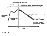
- FIG. 2 is a schematic graph illustrating a control method for decreasing engine output in the event of a failure according to the present embodiment.
- the vertical axis represents engine speed, and the horizontal axis represents time.
- the control mode of the engine 11 is switched from normal control mode to failure control mode in which the engine output is decreased (moderate speed reduction control mode).
- target rotational speed (see a graph shown by a thin solid line) is set that is required for the engine speed after the occurrence of the failure to decrease the engine output.
- the target rotational speed is set together with minimum target rotational speed, which is a lower limit value of the target rotational speed range.
- the engine speed (see a graph shown by a thick solid line) is detected, and when the detected speed is larger than the preset target rotational speed, ignition to the engine is cut off. Cutting off the ignition causes the engine speed to decrease.
- the ignition to the engine is performed normally, so that the engine speed increases temporarily.
- the ignition is again cut off. The engine speed thereby decreases again.
- Repetitively cutting off the ignition in such manner can cause the engine speed to decrease according to the target rotational speed while the engine speed increases and decreases at very short time intervals relative to the target rotational speed.
- the engine speed is kept at the minimum target rotational speed.
- the minimum target rotational speed is set at least to a value larger than the engine speed at idle, even when the engine output is decreased after the occurrence of the failure, the operable state of the vehicle can be maintained.
- Means for decreasing the engine output according to the present embodiment is similar to a method of decreasing the frequency of ignition. Whether or not the ignition should be cut off is determined based on the preset target rotational speed, thereby uniquely defining a decrease in the engine output.
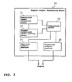
- FIG. 3 illustrates the configuration of engine output decreasing means 20 for decreasing engine output in the event of a failure according to the present embodiment.
- the engine output decreasing means 20 includes rotational speed detection means 21 for detecting engine speed after the occurrence of a failure; target rotational speed setting means 22 for setting the engine speed after the occurrence of the failure to target rotational speed required to decrease engine output; and comparison means 23 for comparing values of the engine speed and the target rotational speed.
- an ignition cutoff signal is transmitted to an ignition control section 24 so that ignition to the engine is cut off.
- an injection stop signal is transmitted to an injection control section 25 so that fuel injection is stopped.
- the rotational speed detection means 21, the ignition control section 24, and the injection control section 25 may be used also in the normal operation.
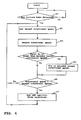
- the fail detection section 13 detects whether or not a failure has occurred in the throttle valve 12 (step S1).
- the target rotational speed setting means 22 sets target rotational speed (step S2).
- the target rotational speed is set to a value required for the engine speed after the occurrence of the failure to decrease engine output.
- the rotational speed detection means 21 detects engine speed (step S3).
- step S4 it is determined whether or not the detected engine speed is equal to or lower than minimum target rotational speed.
- the comparison means 23 compares the target rotational speed set in the step S2 with the engine speed detected in the step S3 (step S6).
- step S6 when the detected rotational speed is larger than the target rotational speed, ignition to the engine is cut off (or fuel injection is stopped, as well as ignition being cut off) (step S7). Meanwhile, when the detected rotational speed is smaller than the target rotational speed, the process returns to the step S2 and repeats the step S2 through the step S7. When the detected rotational speed is smaller than the target rotational speed, the ignition is performed normally.
- the engine speed after the occurrence of the failure can be decreased according to the target rotational speed.
- the target rotational speed is fixed to the minimum target rotational speed (step S5) and thereafter the engine speed is kept at the minimum target rotational speed.
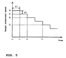
- the target rotational speed is basically set to a value at which engine output is decreased while giving the rider less uncomfortable feeling. An example of such setting is described below with reference to FIG. 5.
- N i is set to a certain value of N min and kept at it thereafter, as shown in FIG. 2.
- the target rotational speed setting means 22 by storing only the values of ⁇ T, ⁇ N and N min in the target rotational speed setting means 22, the target rotational speed can be easily set using the equation (1) as well as the engine speed No detected in the event of a failure.
- ⁇ T and ⁇ N are constant, but the values of ⁇ T and/or ⁇ N may be gradually increased with a lapse of time after the occurrence of a failure.
- the target rotational speed suitable for a vehicle to which the present embodiment is applied may be obtained by actual measurement and stored in the storage means.
- the time ⁇ T can be set arbitrarily. However, the time ⁇ T may be set at the timing at which the step S5 of comparing the rotational speed and the target rotational speed shown in FIG. 4 is executed.
- the timing at which the step S5 is executed can be set arbitrarily, but typically the step S5 is executed every 5 through 10 ms.
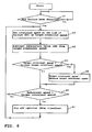
- FIG. 6 A flowchart of an engine control method using the method of setting target rotational speed shown in FIG. 5 is shown in FIG. 6.
- the fail detection section 13 detects whether or not a failure has occurred in the throttle valve 12 (step S1).
- engine speed (No) at the time of the occurrence of the failure is set as target rotational speed (N i ) (step S2).
- ⁇ T After a lapse of predetermined time ( ⁇ T), a subtraction value ( ⁇ N) is subtracted from the target rotational speed (N i ) (step S3).
- the target rotational speed (N i ) and preset minimum target rotational speed (N min ) are compared to each other (step S4).
- the target rotational speed (N i ) is larger than the minimum target rotational speed (N min )
- the detected engine speed and the target rotational speed (N i ) are compared to each other (step S6).
- ignition to the engine is cut off (or fuel injection is stopped, as well as ignition being cut off) (step S7).
- the detected engine speed is smaller than the target rotational speed (N i )
- the ignition is performed normally.
- step S2 through the step S7 are repeated, and the subtraction value ( ⁇ N) is subtracted from the target rotational speed (N i ) in the step S3.
- the target rotational speed (N i ) is decreased to the minimum target rotational speed (N min ) (step S4), the target rotational speed (N i ) is set to a certain value of the minimum target rotational speed (N min ) and kept at it thereafter (step S5).
- the engine speed after the occurrence of the failure can be decreased according to the target rotational speed (N i ).
- the engine speed is kept at the minimum target rotational speed (N min ) thereafter.
- the engine control device is implemented by the ignition control.
- the engine control device may be implemented by controlling the throttle valve to be rotatively actuated in the closing direction, along with the ignition.
- two-wheeled motor vehicle used herein means a motorcycle, including every motorbike and motor scooter, and, more particularly, is a vehicle which can be tumed by tilting the vehicle body.
- a vehicle equipped with two or more front wheels and/or two or more rear wheels, thus having three or four (or more) wheels in total is also included in the "two-wheeled motor vehicle.”
- the present invention may also be applied to other vehicles, as long as a vehicle can take advantage of effects of the invention. This includes any straddle-type vehicles, such as four-wheeled buggies or all terrain vehicles (ATV) and snowmobiles.
- ATV all terrain vehicles
- the present embodiment provides the excellent advantages as described above.
- the practical application of the embodiment to straddle-type vehicles should involve consideration of the embodiments from an overall viewpoint including other requirements.
- the present embodiment can provide an engine control device capable of decreasing engine output while giving less uncomfortable feeling to the rider in the event of a failure, with a simple configuration.
- an engine control device for a straddle-type vehicle having engine output decreasing means for decreasing engine output when a failure has been detected in a throttle valve control system
- the engine output decreasing means comprising: target rotational speed setting means for setting engine speed after the occurrence of the failure to target rotational speed required to decrease engine output; and rotational speed detection means for detecting the engine speed after the occurrence of the failure, in which when the engine speed detected by the rotational speed detection means is larger than the target rotational speed, an ignition of the engine is cut off.
- the target rotational speed is set to decrease stepwise at regular time intervals based on the engine speed at the time of the occurrence of the failure.
- the target rotational speed has preset minimum target rotational speed, which is a lower limit value of the target rotational speed range.
- the minimum target rotational speed is preferably set at least to a value larger than the engine speed at idle.
- a throttle valve is designed to be rotatively actuated in the closing direction when the failure has been detected in the throttle valve control system.
- the description above further discloses an embodiment of an engine control method for a straddle-type vehicle, having engine output decreasing means for decreasing engine output when a failure is detected in a throttle valve control system, wherein the engine output decreasing means has an output decreasing mode in which engine output is decreased when a failure has been detected in a throttle valve control system, in which in the output decreasing mode, when engine speed after the occurrence of the failure is larger than preset target rotational speed at the time of the occurrence of the failure, an ignition of the engine is cut off.
- the target rotational speed is set to decrease stepwise at regular time intervals based on the engine speed at the time of the occurrence of the failure.
- an engine control device for a straddle-type vehicle of the present embodiments in the case in which a failure has been detected in a throttle valve control system, when engine speed after the occurrence of the failure is larger than preset target rotational speed at the time of the occurrence of the failure, an ignition of the engine is cut off. The engine speed thereby can be decreased according to the preset target rotational speed. Thus, engine output can be decreased uniquely.
- an engine control device for a straddle-type vehicle having engine output decreasing means for decreasing engine output when a failure has been detected in a throttle valve control system
- the engine output decreasing means comprising: target rotational speed setting means for setting an engine speed, after the occurrence of the failure, to a target rotational speed required to decrease engine output; and rotational speed detection means for detecting the engine speed after the occurrence of the failure, wherein when the engine speed detected by the rotational speed detection means is larger than the target rotational speed, an ignition of the engine is cut off.
- an engine control device for a straddle-type vehicle according to the first aspect, wherein the target rotational speed is set to decrease stepwise at regular time intervals based on the engine speed at the time of the occurrence of the failure.
- an engine control device for a straddle-type vehicle according to the first or second aspect, wherein the target rotational speed has preset minimum target rotational speed, which is a lower limit value of the target rotational speed range.
- an engine control device for a straddle-type vehicle according to the third aspect, wherein the minimum target rotational speed is set at least to a value larger than the engine speed at idle.
- an engine control device for a straddle-type vehicle according to the first aspect, wherein when the engine speed detected by the rotational speed detection means is larger than the target rotational speed, fuel injection to the engine is stopped.
- an engine control device for a straddle-type vehicle according to the first aspect, wherein a throttle valve is designed to be rotatively actuated in the closing direction when the failure has been detected in the throttle valve control system.
- an engine control method for a straddle-type vehicle having engine output decreasing means for decreasing engine output when a failure is detected in a throttle valve control system, wherein the engine output decreasing means has an output decreasing mode in which engine output is decreased when a failure has been detected in a throttle valve control system, in the output decreasing mode, when engine speed after the occurrence of the failure is larger than preset target rotational speed at the time of the occurrence of the failure, an ignition of the engine is cut off.
- an engine control method for a straddle-type vehicle wherein in the output decreasing mode, when the engine speed after the occurrence of the failure is larger than the preset target rotational speed at the time of the occurrence of the failure, fuel injection to the engine is stopped.
- an engine control method for a straddle-type vehicle according to the seventh or eight aspect, wherein the target rotational speed is set to decrease stepwise at regular time intervals based on the engine speed at the time of the occurrence of the failure.
- the description still further discloses a straddle-type vehicle with the engine control device according to any one of the above aspects.
- the description above discloses as a particularly preferred embodiment, in order to provide an engine control device capable of decreasing engine output while giving less uncomfortable feeling to the rider in the event of a failure, with a simple configuration, a function to decrease engine output when a failure has been detected in a throttle valve.
- a function to decrease engine output when a failure has been detected in a throttle valve When engine speed after the occurrence of the failure is larger than preset target rotational speed at the time of the occurrence of the failure, an ignition of the engine is cut off. The engine speed thereby can be decreased according to the preset target rotational speed. Thus, engine output can be decreased uniquely.
Landscapes
- Engineering & Computer Science (AREA)
- Chemical & Material Sciences (AREA)
- Combustion & Propulsion (AREA)
- Mechanical Engineering (AREA)
- General Engineering & Computer Science (AREA)
- Signal Processing (AREA)
- Theoretical Computer Science (AREA)
- Electrical Control Of Air Or Fuel Supplied To Internal-Combustion Engine (AREA)
- Electrical Control Of Ignition Timing (AREA)
- Combined Controls Of Internal Combustion Engines (AREA)
- Control Of Vehicle Engines Or Engines For Specific Uses (AREA)
- Output Control And Ontrol Of Special Type Engine (AREA)
- Control Of Throttle Valves Provided In The Intake System Or In The Exhaust System (AREA)
- Ignition Installations For Internal Combustion Engines (AREA)
Applications Claiming Priority (2)
| Application Number | Priority Date | Filing Date | Title |
|---|---|---|---|
| JP2005133783 | 2005-05-02 | ||
| JP2006105062A JP4767069B2 (ja) | 2005-05-02 | 2006-04-06 | 鞍乗型車両のエンジン制御装置及びそのエンジン制御方法 |
Publications (3)
| Publication Number | Publication Date |
|---|---|
| EP1719892A2 true EP1719892A2 (fr) | 2006-11-08 |
| EP1719892A3 EP1719892A3 (fr) | 2008-03-26 |
| EP1719892B1 EP1719892B1 (fr) | 2010-01-06 |
Family
ID=36717013
Family Applications (1)
| Application Number | Title | Priority Date | Filing Date |
|---|---|---|---|
| EP06009077A Ceased EP1719892B1 (fr) | 2005-05-02 | 2006-05-02 | Dispositif et méthode de commande de moteur pour véhicule du type monté à califourchon |
Country Status (5)
| Country | Link |
|---|---|
| US (1) | US7403847B2 (fr) |
| EP (1) | EP1719892B1 (fr) |
| JP (1) | JP4767069B2 (fr) |
| AT (1) | ATE454545T1 (fr) |
| DE (1) | DE602006011529D1 (fr) |
Cited By (1)
| Publication number | Priority date | Publication date | Assignee | Title |
|---|---|---|---|---|
| EP2159095A3 (fr) * | 2008-09-01 | 2014-09-10 | Yamaha Hatsudoki Kabushiki Kaisha | Système de commande pour ralentir un véhicule à la suite d'une erreur lors du contrôle du papillon électrique. |
Families Citing this family (8)
| Publication number | Priority date | Publication date | Assignee | Title |
|---|---|---|---|---|
| DE602007007586D1 (de) * | 2007-05-25 | 2010-08-19 | Magneti Marelli Spa | Regelverfahren für ein Kraftfahrzeug welches im Falle eines Defektes einen Betrieb des Fahrzeugs mit reduzierter Leistung bewirkt |
| JP4840340B2 (ja) * | 2007-11-28 | 2011-12-21 | トヨタ自動車株式会社 | 車両の制御装置 |
| JP5247313B2 (ja) | 2008-09-01 | 2013-07-24 | ヤマハ発動機株式会社 | 制御システムおよび車両 |
| EP2531716B1 (fr) * | 2010-02-02 | 2018-08-15 | Husqvarna AB | Angle d'allumage en alternance avant le pmh |
| WO2012110448A1 (fr) | 2011-02-14 | 2012-08-23 | Fraunhofer-Gesellschaft zur Förderung der angewandten Forschung e.V. | Appareil et procédé de codage d'une partie d'un signal audio au moyen d'une détection de transitoire et d'un résultat de qualité |
| JP5561218B2 (ja) * | 2011-03-23 | 2014-07-30 | 株式会社デンソー | エンジン制御装置 |
| DE102012214518B3 (de) * | 2012-08-15 | 2014-02-06 | Ford Global Technologies, Llc | Verfahren zur Steuerung einer Zündanlage einer Brennkraftmaschine sowie Zündanlage |
| US11352964B2 (en) * | 2017-10-06 | 2022-06-07 | Briggs & Stratton, Llc | Cylinder deactivation for a multiple cylinder engine |
Family Cites Families (37)
| Publication number | Priority date | Publication date | Assignee | Title |
|---|---|---|---|---|
| DE3700088C2 (de) * | 1987-01-03 | 1994-05-11 | Bosch Gmbh Robert | Mehrmotoriges Antriebssystem |
| JPH086611B2 (ja) * | 1987-03-26 | 1996-01-29 | 日産自動車株式会社 | 車載エンジン制御装置 |
| EP0313275B1 (fr) * | 1987-10-19 | 1994-01-12 | Honda Giken Kogyo Kabushiki Kaisha | Méthode de commande du rapport de transmission pour un variateur continu de vitesse |
| JP2600756B2 (ja) * | 1988-02-16 | 1997-04-16 | トヨタ自動車株式会社 | 車両の加速スリップ制御装置 |
| JP2591082B2 (ja) * | 1988-07-07 | 1997-03-19 | 株式会社デンソー | 車両のスリップ制御装置 |
| JP2844671B2 (ja) * | 1989-05-29 | 1999-01-06 | アイシン精機株式会社 | 内燃機関のスロットル制御方法 |
| JPH03237227A (ja) * | 1990-02-14 | 1991-10-23 | Mitsubishi Motors Corp | スロットル装置のフェイルセーフ方法 |
| JP2524246B2 (ja) * | 1990-06-13 | 1996-08-14 | 本田技研工業株式会社 | 駆動輪スリップ制御装置 |
| JPH04203250A (ja) * | 1990-11-29 | 1992-07-23 | Mitsubishi Motors Corp | 走行負荷分補償式速度制御部付ドライブバイワイヤ式車両 |
| US5406483A (en) * | 1991-05-15 | 1995-04-11 | Phoenix International Corporation | Engine variable transmission control system |
| DE4214179C1 (fr) | 1992-04-30 | 1993-05-06 | Mercedes-Benz Aktiengesellschaft, 7000 Stuttgart, De | |
| US5393278A (en) * | 1992-05-02 | 1995-02-28 | Toyota Jidosha Kabushiki Kaisha | Shift control apparatus for shifting up transmission upon re-acceleration following deceleration of vehicle |
| US5445121A (en) * | 1992-11-24 | 1995-08-29 | Yamaha Hatsudoki Kabushiki Kaisha | Engine operational control unit |
| JP3139197B2 (ja) | 1993-02-23 | 2001-02-26 | 日産自動車株式会社 | スロットル駆動装置 |
| US5629852A (en) * | 1993-02-26 | 1997-05-13 | Mitsubishi Denki Kabushiki Kaisha | Vehicle control device for controlling output power of multi-cylinder engine upon emergency |
| DE4426972B4 (de) * | 1994-07-29 | 2005-11-10 | Robert Bosch Gmbh | Verfahren und Vorrichtung zur Steuerung einer Brennkraftmaschine |
| DE4443502A1 (de) * | 1994-12-07 | 1996-06-13 | Bosch Gmbh Robert | Vorrichtung für eine Brennkraftmaschine |
| DE19509492C2 (de) * | 1995-03-16 | 1998-08-27 | Daimler Benz Ag | Verfahren und Vorrichtung zur Geschwindigkeitsbegrenzung eines Kraftfahrzeuges |
| DE19615542C2 (de) * | 1996-04-19 | 1998-05-07 | Daimler Benz Ag | Einrichtung zur Motorlastbestimmung für einen Verbrennungsmotor |
| US6505594B1 (en) * | 1999-08-23 | 2003-01-14 | Toyota Jidosha Kabushiki Kaisha | Control apparatus for internal combustion engine and method of controlling internal combustion engine |
| JP3427793B2 (ja) * | 1999-08-27 | 2003-07-22 | トヨタ自動車株式会社 | 車両用自動変速機の制御装置 |
| JP2001182591A (ja) * | 1999-12-24 | 2001-07-06 | Honda Motor Co Ltd | 内燃機関の制御装置 |
| JP4235376B2 (ja) * | 2000-10-16 | 2009-03-11 | 株式会社日立製作所 | 内燃機関におけるフェールセーフ処理装置 |
| JP2002195076A (ja) * | 2000-12-27 | 2002-07-10 | Daihatsu Motor Co Ltd | 内燃機関の制御方法 |
| JP2003065140A (ja) | 2001-08-29 | 2003-03-05 | Yamaha Motor Co Ltd | エンジン制御装置 |
| JP3826014B2 (ja) * | 2001-11-02 | 2006-09-27 | 愛三工業株式会社 | 電子スロットル制御装置 |
| JP3816416B2 (ja) * | 2002-03-28 | 2006-08-30 | 三菱電機株式会社 | 電子スロットル制御システムのフェイルセーフ装置 |
| JP4121318B2 (ja) * | 2002-06-26 | 2008-07-23 | 三菱電機株式会社 | 車両用のエンジン制御装置 |
| JP2004028288A (ja) * | 2002-06-28 | 2004-01-29 | Hitachi Ltd | 車両の安全制御装置 |
| JP2004092634A (ja) * | 2002-07-12 | 2004-03-25 | Kokusan Denki Co Ltd | 発電機搭載内燃機関駆動車両 |
| JP4007123B2 (ja) * | 2002-08-26 | 2007-11-14 | トヨタ自動車株式会社 | 内燃機関の制御装置 |
| JP2004225538A (ja) * | 2003-01-20 | 2004-08-12 | Mitsubishi Electric Corp | スロットルバルブ制御装置 |
| US7280910B2 (en) * | 2003-06-05 | 2007-10-09 | Nissan Motor Co., Ltd. | Engine protection method and apparatus, and engine power control method and apparatus for cargo handling vehicle |
| JP4214405B2 (ja) * | 2004-08-19 | 2009-01-28 | 株式会社デンソー | 自動変速機の制御装置 |
| JP2006118387A (ja) * | 2004-10-20 | 2006-05-11 | Yamaha Marine Co Ltd | エンジンの制御装置 |
| JP4462073B2 (ja) * | 2005-03-08 | 2010-05-12 | 株式会社デンソー | 車両用内燃機関の電子スロットル制御装置 |
| CA2572595C (fr) * | 2006-01-26 | 2011-03-29 | Honda Motor Co., Ltd | Machine de travaux entrainee par moteur |
-
2006
- 2006-04-06 JP JP2006105062A patent/JP4767069B2/ja not_active Expired - Fee Related
- 2006-04-20 US US11/408,592 patent/US7403847B2/en not_active Expired - Lifetime
- 2006-05-02 DE DE602006011529T patent/DE602006011529D1/de not_active Expired - Lifetime
- 2006-05-02 EP EP06009077A patent/EP1719892B1/fr not_active Ceased
- 2006-05-02 AT AT06009077T patent/ATE454545T1/de not_active IP Right Cessation
Cited By (1)
| Publication number | Priority date | Publication date | Assignee | Title |
|---|---|---|---|---|
| EP2159095A3 (fr) * | 2008-09-01 | 2014-09-10 | Yamaha Hatsudoki Kabushiki Kaisha | Système de commande pour ralentir un véhicule à la suite d'une erreur lors du contrôle du papillon électrique. |
Also Published As
| Publication number | Publication date |
|---|---|
| JP4767069B2 (ja) | 2011-09-07 |
| ATE454545T1 (de) | 2010-01-15 |
| US7403847B2 (en) | 2008-07-22 |
| EP1719892B1 (fr) | 2010-01-06 |
| JP2006336640A (ja) | 2006-12-14 |
| EP1719892A3 (fr) | 2008-03-26 |
| US20060287796A1 (en) | 2006-12-21 |
| DE602006011529D1 (de) | 2010-02-25 |
Similar Documents
| Publication | Publication Date | Title |
|---|---|---|
| US8221287B2 (en) | Vehicle and controller thereof | |
| US8160790B2 (en) | Vehicle speed control system and straddle-type vehicle | |
| EP2796693B1 (fr) | Dispositif de commande d'injection de carburant | |
| US20090171546A1 (en) | Control device for straddle-type vehicle and vehicle equipped with the same | |
| EP1722084B1 (fr) | Appareil et procédé de commande d'un papillon | |
| RU2660235C2 (ru) | Способ (варианты ) эксплуатации транспортного средства | |
| JP2008095635A (ja) | 駆動力制御装置 | |
| EP1719892A2 (fr) | Dispositif et méthode de commande de moteur pour véhicule du type monté à califourchon | |
| US8425380B2 (en) | Engine controlling apparatus for motorcycle | |
| JP3708718B2 (ja) | 自動車用エンジンの出力制御装置 | |
| EP2573369B1 (fr) | Appareil et méthode de commande de force motrice | |
| CA2921950A1 (fr) | Dispositif de commande de la force de reaction de la pedale d'accelerateur | |
| US8826885B2 (en) | Fuel injection control system | |
| JP2019064413A (ja) | 車両用制御装置 | |
| JP4326316B2 (ja) | 車両のトラクションコントロール装置 | |
| JP2008280991A (ja) | トルク制御装置 | |
| JP4269925B2 (ja) | エンジンの燃料供給停止制御装置 | |
| KR100373032B1 (ko) | 수동 변속 차량의 엔진 회전수 제어장치 및 방법 | |
| JP6695289B2 (ja) | 内燃機関制御装置 | |
| EP3974273B1 (fr) | Moto | |
| US20230313852A1 (en) | Mobile body and mobile body control method | |
| JP2518087B2 (ja) | 車両のアクセル全閉位置学習装置 | |
| JP2011027116A (ja) | 鞍乗型車両のエンジン制御装置及びエンジン制御方法 | |
| JP2518452B2 (ja) | 車両の出力制御装置 | |
| KR0154628B1 (ko) | 자동차 급출발 방지 제어방법 |
Legal Events
| Date | Code | Title | Description |
|---|---|---|---|
| PUAI | Public reference made under article 153(3) epc to a published international application that has entered the european phase |
Free format text: ORIGINAL CODE: 0009012 |
|
| AK | Designated contracting states |
Kind code of ref document: A2 Designated state(s): AT BE BG CH CY CZ DE DK EE ES FI FR GB GR HU IE IS IT LI LT LU LV MC NL PL PT RO SE SI SK TR |
|
| AX | Request for extension of the european patent |
Extension state: AL BA HR MK YU |
|
| 17P | Request for examination filed |
Effective date: 20061117 |
|
| PUAL | Search report despatched |
Free format text: ORIGINAL CODE: 0009013 |
|
| AK | Designated contracting states |
Kind code of ref document: A3 Designated state(s): AT BE BG CH CY CZ DE DK EE ES FI FR GB GR HU IE IS IT LI LT LU LV MC NL PL PT RO SE SI SK TR |
|
| AX | Request for extension of the european patent |
Extension state: AL BA HR MK YU |
|
| 17Q | First examination report despatched |
Effective date: 20080530 |
|
| AKX | Designation fees paid |
Designated state(s): AT BE BG CH CY CZ DE DK EE ES FI FR GB GR HU IE IS IT LI LT LU LV MC NL PL PT RO SE SI SK TR |
|
| GRAJ | Information related to disapproval of communication of intention to grant by the applicant or resumption of examination proceedings by the epo deleted |
Free format text: ORIGINAL CODE: EPIDOSDIGR1 |
|
| GRAP | Despatch of communication of intention to grant a patent |
Free format text: ORIGINAL CODE: EPIDOSNIGR1 |
|
| GRAS | Grant fee paid |
Free format text: ORIGINAL CODE: EPIDOSNIGR3 |
|
| GRAA | (expected) grant |
Free format text: ORIGINAL CODE: 0009210 |
|
| AK | Designated contracting states |
Kind code of ref document: B1 Designated state(s): AT BE BG CH CY CZ DE DK EE ES FI FR GB GR HU IE IS IT LI LT LU LV MC NL PL PT RO SE SI SK TR |
|
| REG | Reference to a national code |
Ref country code: GB Ref legal event code: FG4D |
|
| REG | Reference to a national code |
Ref country code: CH Ref legal event code: EP |
|
| REG | Reference to a national code |
Ref country code: IE Ref legal event code: FG4D |
|
| REF | Corresponds to: |
Ref document number: 602006011529 Country of ref document: DE Date of ref document: 20100225 Kind code of ref document: P |
|
| REG | Reference to a national code |
Ref country code: NL Ref legal event code: VDEP Effective date: 20100106 |
|
| PG25 | Lapsed in a contracting state [announced via postgrant information from national office to epo] |
Ref country code: SI Free format text: LAPSE BECAUSE OF FAILURE TO SUBMIT A TRANSLATION OF THE DESCRIPTION OR TO PAY THE FEE WITHIN THE PRESCRIBED TIME-LIMIT Effective date: 20100106 |
|
| LTIE | Lt: invalidation of european patent or patent extension |
Effective date: 20100106 |
|
| PG25 | Lapsed in a contracting state [announced via postgrant information from national office to epo] |
Ref country code: AT Free format text: LAPSE BECAUSE OF FAILURE TO SUBMIT A TRANSLATION OF THE DESCRIPTION OR TO PAY THE FEE WITHIN THE PRESCRIBED TIME-LIMIT Effective date: 20100106 |
|
| PG25 | Lapsed in a contracting state [announced via postgrant information from national office to epo] |
Ref country code: LT Free format text: LAPSE BECAUSE OF FAILURE TO SUBMIT A TRANSLATION OF THE DESCRIPTION OR TO PAY THE FEE WITHIN THE PRESCRIBED TIME-LIMIT Effective date: 20100106 Ref country code: NL Free format text: LAPSE BECAUSE OF FAILURE TO SUBMIT A TRANSLATION OF THE DESCRIPTION OR TO PAY THE FEE WITHIN THE PRESCRIBED TIME-LIMIT Effective date: 20100106 Ref country code: ES Free format text: LAPSE BECAUSE OF FAILURE TO SUBMIT A TRANSLATION OF THE DESCRIPTION OR TO PAY THE FEE WITHIN THE PRESCRIBED TIME-LIMIT Effective date: 20100417 Ref country code: IS Free format text: LAPSE BECAUSE OF FAILURE TO SUBMIT A TRANSLATION OF THE DESCRIPTION OR TO PAY THE FEE WITHIN THE PRESCRIBED TIME-LIMIT Effective date: 20100506 Ref country code: PT Free format text: LAPSE BECAUSE OF FAILURE TO SUBMIT A TRANSLATION OF THE DESCRIPTION OR TO PAY THE FEE WITHIN THE PRESCRIBED TIME-LIMIT Effective date: 20100506 |
|
| PG25 | Lapsed in a contracting state [announced via postgrant information from national office to epo] |
Ref country code: FI Free format text: LAPSE BECAUSE OF FAILURE TO SUBMIT A TRANSLATION OF THE DESCRIPTION OR TO PAY THE FEE WITHIN THE PRESCRIBED TIME-LIMIT Effective date: 20100106 Ref country code: PL Free format text: LAPSE BECAUSE OF FAILURE TO SUBMIT A TRANSLATION OF THE DESCRIPTION OR TO PAY THE FEE WITHIN THE PRESCRIBED TIME-LIMIT Effective date: 20100106 Ref country code: LV Free format text: LAPSE BECAUSE OF FAILURE TO SUBMIT A TRANSLATION OF THE DESCRIPTION OR TO PAY THE FEE WITHIN THE PRESCRIBED TIME-LIMIT Effective date: 20100106 |
|
| PG25 | Lapsed in a contracting state [announced via postgrant information from national office to epo] |
Ref country code: SE Free format text: LAPSE BECAUSE OF FAILURE TO SUBMIT A TRANSLATION OF THE DESCRIPTION OR TO PAY THE FEE WITHIN THE PRESCRIBED TIME-LIMIT Effective date: 20100106 Ref country code: BE Free format text: LAPSE BECAUSE OF FAILURE TO SUBMIT A TRANSLATION OF THE DESCRIPTION OR TO PAY THE FEE WITHIN THE PRESCRIBED TIME-LIMIT Effective date: 20100106 Ref country code: CY Free format text: LAPSE BECAUSE OF FAILURE TO SUBMIT A TRANSLATION OF THE DESCRIPTION OR TO PAY THE FEE WITHIN THE PRESCRIBED TIME-LIMIT Effective date: 20100106 Ref country code: EE Free format text: LAPSE BECAUSE OF FAILURE TO SUBMIT A TRANSLATION OF THE DESCRIPTION OR TO PAY THE FEE WITHIN THE PRESCRIBED TIME-LIMIT Effective date: 20100106 Ref country code: GR Free format text: LAPSE BECAUSE OF FAILURE TO SUBMIT A TRANSLATION OF THE DESCRIPTION OR TO PAY THE FEE WITHIN THE PRESCRIBED TIME-LIMIT Effective date: 20100407 Ref country code: RO Free format text: LAPSE BECAUSE OF FAILURE TO SUBMIT A TRANSLATION OF THE DESCRIPTION OR TO PAY THE FEE WITHIN THE PRESCRIBED TIME-LIMIT Effective date: 20100106 |
|
| PLBE | No opposition filed within time limit |
Free format text: ORIGINAL CODE: 0009261 |
|
| STAA | Information on the status of an ep patent application or granted ep patent |
Free format text: STATUS: NO OPPOSITION FILED WITHIN TIME LIMIT |
|
| PG25 | Lapsed in a contracting state [announced via postgrant information from national office to epo] |
Ref country code: BG Free format text: LAPSE BECAUSE OF FAILURE TO SUBMIT A TRANSLATION OF THE DESCRIPTION OR TO PAY THE FEE WITHIN THE PRESCRIBED TIME-LIMIT Effective date: 20100406 Ref country code: CZ Free format text: LAPSE BECAUSE OF FAILURE TO SUBMIT A TRANSLATION OF THE DESCRIPTION OR TO PAY THE FEE WITHIN THE PRESCRIBED TIME-LIMIT Effective date: 20100106 Ref country code: SK Free format text: LAPSE BECAUSE OF FAILURE TO SUBMIT A TRANSLATION OF THE DESCRIPTION OR TO PAY THE FEE WITHIN THE PRESCRIBED TIME-LIMIT Effective date: 20100106 |
|
| 26N | No opposition filed |
Effective date: 20101007 |
|
| PG25 | Lapsed in a contracting state [announced via postgrant information from national office to epo] |
Ref country code: MC Free format text: LAPSE BECAUSE OF NON-PAYMENT OF DUE FEES Effective date: 20100531 |
|
| REG | Reference to a national code |
Ref country code: CH Ref legal event code: PL |
|
| PG25 | Lapsed in a contracting state [announced via postgrant information from national office to epo] |
Ref country code: DK Free format text: LAPSE BECAUSE OF FAILURE TO SUBMIT A TRANSLATION OF THE DESCRIPTION OR TO PAY THE FEE WITHIN THE PRESCRIBED TIME-LIMIT Effective date: 20100106 |
|
| PG25 | Lapsed in a contracting state [announced via postgrant information from national office to epo] |
Ref country code: CH Free format text: LAPSE BECAUSE OF NON-PAYMENT OF DUE FEES Effective date: 20100531 Ref country code: LI Free format text: LAPSE BECAUSE OF NON-PAYMENT OF DUE FEES Effective date: 20100531 |
|
| PG25 | Lapsed in a contracting state [announced via postgrant information from national office to epo] |
Ref country code: IT Free format text: LAPSE BECAUSE OF FAILURE TO SUBMIT A TRANSLATION OF THE DESCRIPTION OR TO PAY THE FEE WITHIN THE PRESCRIBED TIME-LIMIT Effective date: 20100106 |
|
| PG25 | Lapsed in a contracting state [announced via postgrant information from national office to epo] |
Ref country code: IE Free format text: LAPSE BECAUSE OF NON-PAYMENT OF DUE FEES Effective date: 20100502 |
|
| PG25 | Lapsed in a contracting state [announced via postgrant information from national office to epo] |
Ref country code: LU Free format text: LAPSE BECAUSE OF NON-PAYMENT OF DUE FEES Effective date: 20100502 Ref country code: HU Free format text: LAPSE BECAUSE OF FAILURE TO SUBMIT A TRANSLATION OF THE DESCRIPTION OR TO PAY THE FEE WITHIN THE PRESCRIBED TIME-LIMIT Effective date: 20100707 |
|
| PG25 | Lapsed in a contracting state [announced via postgrant information from national office to epo] |
Ref country code: TR Free format text: LAPSE BECAUSE OF FAILURE TO SUBMIT A TRANSLATION OF THE DESCRIPTION OR TO PAY THE FEE WITHIN THE PRESCRIBED TIME-LIMIT Effective date: 20100106 |
|
| REG | Reference to a national code |
Ref country code: FR Ref legal event code: PLFP Year of fee payment: 11 |
|
| REG | Reference to a national code |
Ref country code: FR Ref legal event code: PLFP Year of fee payment: 12 |
|
| REG | Reference to a national code |
Ref country code: FR Ref legal event code: PLFP Year of fee payment: 13 |
|
| P01 | Opt-out of the competence of the unified patent court (upc) registered |
Effective date: 20230527 |
|
| PGFP | Annual fee paid to national office [announced via postgrant information from national office to epo] |
Ref country code: GB Payment date: 20240521 Year of fee payment: 19 |
|
| PGFP | Annual fee paid to national office [announced via postgrant information from national office to epo] |
Ref country code: DE Payment date: 20240521 Year of fee payment: 19 |
|
| PGFP | Annual fee paid to national office [announced via postgrant information from national office to epo] |
Ref country code: FR Payment date: 20240529 Year of fee payment: 19 |
|
| REG | Reference to a national code |
Ref country code: DE Ref legal event code: R119 Ref document number: 602006011529 Country of ref document: DE |
|
| GBPC | Gb: european patent ceased through non-payment of renewal fee |
Effective date: 20250502 |
|
| PG25 | Lapsed in a contracting state [announced via postgrant information from national office to epo] |
Ref country code: GB Free format text: LAPSE BECAUSE OF NON-PAYMENT OF DUE FEES Effective date: 20250502 |
|
| PG25 | Lapsed in a contracting state [announced via postgrant information from national office to epo] |
Ref country code: DE Free format text: LAPSE BECAUSE OF NON-PAYMENT OF DUE FEES Effective date: 20251202 |
|
| PG25 | Lapsed in a contracting state [announced via postgrant information from national office to epo] |
Ref country code: FR Free format text: LAPSE BECAUSE OF NON-PAYMENT OF DUE FEES Effective date: 20250531 |