EP1719921A2 - Assemblage de valves pour amortir les vibrations dans un système d'entraînement hydraulique comprenant un cylindre émetteur et un cylindre récepteur - Google Patents
Assemblage de valves pour amortir les vibrations dans un système d'entraînement hydraulique comprenant un cylindre émetteur et un cylindre récepteur Download PDFInfo
- Publication number
- EP1719921A2 EP1719921A2 EP06006509A EP06006509A EP1719921A2 EP 1719921 A2 EP1719921 A2 EP 1719921A2 EP 06006509 A EP06006509 A EP 06006509A EP 06006509 A EP06006509 A EP 06006509A EP 1719921 A2 EP1719921 A2 EP 1719921A2
- Authority
- EP
- European Patent Office
- Prior art keywords
- valve
- valve body
- housing
- hydraulic
- arrangement
- Prior art date
- Legal status (The legal status is an assumption and is not a legal conclusion. Google has not performed a legal analysis and makes no representation as to the accuracy of the status listed.)
- Granted
Links
Images



Classifications
-
- F—MECHANICAL ENGINEERING; LIGHTING; HEATING; WEAPONS; BLASTING
- F15—FLUID-PRESSURE ACTUATORS; HYDRAULICS OR PNEUMATICS IN GENERAL
- F15B—SYSTEMS ACTING BY MEANS OF FLUIDS IN GENERAL; FLUID-PRESSURE ACTUATORS, e.g. SERVOMOTORS; DETAILS OF FLUID-PRESSURE SYSTEMS, NOT OTHERWISE PROVIDED FOR
- F15B21/00—Common features of fluid actuator systems; Fluid-pressure actuator systems or details thereof, not covered by any other group of this subclass
- F15B21/008—Reduction of noise or vibration
-
- F—MECHANICAL ENGINEERING; LIGHTING; HEATING; WEAPONS; BLASTING
- F15—FLUID-PRESSURE ACTUATORS; HYDRAULICS OR PNEUMATICS IN GENERAL
- F15B—SYSTEMS ACTING BY MEANS OF FLUIDS IN GENERAL; FLUID-PRESSURE ACTUATORS, e.g. SERVOMOTORS; DETAILS OF FLUID-PRESSURE SYSTEMS, NOT OTHERWISE PROVIDED FOR
- F15B7/00—Systems in which the movement produced is definitely related to the output of a volumetric pump; Telemotors
-
- F—MECHANICAL ENGINEERING; LIGHTING; HEATING; WEAPONS; BLASTING
- F16—ENGINEERING ELEMENTS AND UNITS; GENERAL MEASURES FOR PRODUCING AND MAINTAINING EFFECTIVE FUNCTIONING OF MACHINES OR INSTALLATIONS; THERMAL INSULATION IN GENERAL
- F16D—COUPLINGS FOR TRANSMITTING ROTATION; CLUTCHES; BRAKES
- F16D48/00—External control of clutches
- F16D48/02—Control by fluid pressure
-
- F—MECHANICAL ENGINEERING; LIGHTING; HEATING; WEAPONS; BLASTING
- F16—ENGINEERING ELEMENTS AND UNITS; GENERAL MEASURES FOR PRODUCING AND MAINTAINING EFFECTIVE FUNCTIONING OF MACHINES OR INSTALLATIONS; THERMAL INSULATION IN GENERAL
- F16D—COUPLINGS FOR TRANSMITTING ROTATION; CLUTCHES; BRAKES
- F16D48/00—External control of clutches
- F16D48/02—Control by fluid pressure
- F16D2048/0215—Control by fluid pressure for damping of pulsations within the fluid system
-
- F—MECHANICAL ENGINEERING; LIGHTING; HEATING; WEAPONS; BLASTING
- F16—ENGINEERING ELEMENTS AND UNITS; GENERAL MEASURES FOR PRODUCING AND MAINTAINING EFFECTIVE FUNCTIONING OF MACHINES OR INSTALLATIONS; THERMAL INSULATION IN GENERAL
- F16D—COUPLINGS FOR TRANSMITTING ROTATION; CLUTCHES; BRAKES
- F16D2300/00—Special features for couplings or clutches
- F16D2300/22—Vibration damping
-
- F—MECHANICAL ENGINEERING; LIGHTING; HEATING; WEAPONS; BLASTING
- F16—ENGINEERING ELEMENTS AND UNITS; GENERAL MEASURES FOR PRODUCING AND MAINTAINING EFFECTIVE FUNCTIONING OF MACHINES OR INSTALLATIONS; THERMAL INSULATION IN GENERAL
- F16D—COUPLINGS FOR TRANSMITTING ROTATION; CLUTCHES; BRAKES
- F16D25/00—Fluid-actuated clutches
- F16D25/08—Fluid-actuated clutches with fluid-actuated member not rotating with a clutching member
- F16D25/082—Fluid-actuated clutches with fluid-actuated member not rotating with a clutching member the line of action of the fluid-actuated members co-inciding with the axis of rotation
-
- F—MECHANICAL ENGINEERING; LIGHTING; HEATING; WEAPONS; BLASTING
- F16—ENGINEERING ELEMENTS AND UNITS; GENERAL MEASURES FOR PRODUCING AND MAINTAINING EFFECTIVE FUNCTIONING OF MACHINES OR INSTALLATIONS; THERMAL INSULATION IN GENERAL
- F16D—COUPLINGS FOR TRANSMITTING ROTATION; CLUTCHES; BRAKES
- F16D25/00—Fluid-actuated clutches
- F16D25/12—Details not specific to one of the before-mentioned types
- F16D25/14—Fluid pressure control
Definitions
- the present invention relates to a switchable between a master cylinder and a slave cylinder of a hydraulic power transmission system for vibration isolation, according to the preamble of patent claim 1, and their use in a hydraulic power transmission system, according to claim 14.
- the invention relates to such Valve assembly as it is mass used in hydraulic clutch actuation for motor vehicles.
- a conventional hydraulic clutch actuator has a master cylinder that can be operated via a clutch pedal and connected to a surge tank.
- the master cylinder is hydraulically connected via a pressure line with a slave cylinder, so that the pressure generated by depressing the clutch pedal in the master cylinder via the liquid column in the pressure line to the slave cylinder is transferable.
- the release bearing of the clutch is acted upon by the slave cylinder with an actuating force to separate via a release mechanism, the clutch pressure plate from the Kupplungsmit kindergarten and thus the internal combustion engine from the transmission of the motor vehicle.
- the unwanted SchwingüngsGermantragung on the master cylinder can be reduced by changes in the pipe system between the slave cylinder and the master cylinder.
- Longer pipelines lead, for example, to lower vibrations, because the damping increases due to the greater flow resistance.
- the higher mass of hydraulic fluid in the longer pipe plays a role here.
- the installation of orifices or chokes also causes a higher flow resistance and thus slightly lower vibrations.
- this form of damping are set relatively narrow limits, because the measures described also cause an undesirable increase in applied to the clutch pedal Power during rapid operation, especially at low temperatures.
- the return speed of the clutch pedal also decreases in these measures in an undesirable manner, again especially at low temperatures, because the hydraulic medium - usually brake fluid - is already relatively tough here.
- JP 59-89834 A (Fig. 1) a switchable between a master cylinder and a slave cylinder hydraulic clutch actuation valve assembly for vibration decoupling, which has a housing with a first, connectable to the master cylinder hydraulic connection and a second, connectable to the slave cylinder hydraulic connection. Between the hydraulic connections, two valve bodies are accommodated in the housing. The first, piston-like and sealed by an outer peripheral side sealing member relative to the housing valve body is biased by a first spring member in a first direction against a housing-fixed stop and has a formed by two through-holes passageway for the hydraulic fluid.
- the second, plunger-like valve body is biased by a second spring element in a direction opposite to the first direction second direction against a valve seat on the first valve body, so that the second valve body substantially closes the passageway in the first valve body in a basic position of this valve arrangement and at a flow rate in lifts the first direction from the valve seat on the first valve body to open the passageway in the first valve body for a flow through the valve assembly.
- the second valve body of the valve assembly engages the first valve body with a shaft which in the basic position of the valve assembly projects from the first valve body in the second direction in order to be able to cooperate with a further stop surface on the housing.
- the valve body can resonate with the pressure pulsations in the liquid column between the slave cylinder and the master cylinder, so that not isolated via the slave cylinder in the liquid column induced vibrations of the valve assembly, but on the Master cylinder and thus the clutch pedal are transmitted.
- the invention is based on the prior art according to the JP 59-89834 A the object to provide a switchable between a master cylinder and a slave cylinder of a hydraulic power transmission system, as simple and compact trained valve assembly for vibration decoupling, on the one hand has the lowest possible resistance to displacement of the liquid column between the master and the slave cylinder and on the other hand compared with the generic state of the art - is able to more effectively prevent vibration transmission from the slave cylinder to the master cylinder.
- a switchable between a master and a slave cylinder of a hydraulic power transmission system for vibration isolation which has a housing having a first and a second hydraulic port, and two valve body, which are accommodated between the hydraulic ports in the housing, wherein the first valve body is biased by a first spring member in a first direction against a housing fixed stop and having a passageway for the hydraulic fluid, while the second valve body biased by a second spring member in a direction opposite to the first direction second direction against a valve seat on the first valve body is, so that the second valve body in a basic position of the valve assembly, the passageway in the first valve body completely or almost completely closes and at a flow in the he most direction from the valve seat lifts to open the passageway for a flow through the valve assembly, between the first valve body and the housing another passageway provided for the hydraulic fluid, wherein the housing fixed stop a further valve seat is formed, against which the first valve body is biased so that the first valve body in the basic position of the valve assembly closes the further passageway
- the liquid flow in the second direction has only an advantageously low resistance oppose, as well as the other valve seat on the housing-fixed stop which completely or almost completely closes the further passageway in cooperation with the spring-biased first valve body (basic position of the valve assembly) or releases at a flow in the second direction, causes in a simple manner that none the valve body must first cover a predetermined path before the respective valve seat is opened.
- valve assembly ensures that no excessive residual pressure in the respective liquid column section builds up in the return of the respective valve body under the force of the respective associated spring element, which retards a return of the respective valve body to its normal position.
- the valve assembly according to the invention immediately opens at a volumetric flow, irrespective of its direction, and immediately closes upon interruption of the volumetric flow, so that the valve bodies are always "grounded” to the housing of the valve assembly when the liquid column is not moved, and thus Maintaining pressure pulsations in the one slave cylinder side liquid column section from the other, donor cylinder side liquid column section substantially.
- valve assembly according to the invention in the generic state of the art between the first valve body and the housing provided sealing element, so that the associated friction losses, which may have a negative effect on the return speed of the clutch pedal, in the valve assembly according to the invention advantageously not occur.
- the sealing surfaces of the valve seats are arranged with respect to the displacement of the valve body, that the sealing surface of the (first) valve seat and / or the sealing surface of the other valve seat perpendicular to the direction of displacement of the first and second valve body is so that upon displacement of the respective valve body as large a flow cross-section between the respective valve body and the associated valve seat is released to provide here for the smallest possible flow resistance.
- the sealing surface of the (first) valve seat and the sealing surface of the further valve seat in the basic position of the valve arrangement lie in one plane, an advantageously compact valve arrangement results in the axial direction.
- the housing of the valve arrangement is divided into two, with a base part and a plug-in part secured therein, the valve bodies and the spring elements being arranged between the base part and the plug-in part. It can advantageously form the male part with an end face the housing-fixed stop for the first valve body, so that there are no additional components to provide or measures to take.
- the second valve body may be provided in a particularly simple manufacturing design outside circumference with a plurality of webs, which serve the leadership of the second valve body in a bore of the first valve body and - at the same time - limit together with the wall of the valve body bore the (first) passageway.
- the first valve body may be provided on the outer peripheral side with a plurality of ribs, which serve to guide the first valve body in a bore of the housing and - at the same time - Limit together with the wall of the housing bore the other passageway, which can also be easily realized manufacturing technology.
- first spring element and / or the second spring element is a helical compression spring.
- the main parts of the valve arrangement can be produced from a metallic material, for example an aluminum alloy, such as by machining.
- a metallic material for example an aluminum alloy, such as by machining.
- the receipt of a low-cost valve arrangement is conducive, however, if the housing or its parts and / or the first valve body and / or the second valve body is injection-molded from plastic.
- a volume sensor may be mounted adjacent the first or second valve body in a bore of the housing of the valve assembly that is elastically deformable under pressure to dampen or reduce residual vibration.
- Such residual vibrations can occur when the pressure amplitudes of the pressure pulsations in the liquid column, namely in the liquid column section between the slave cylinder and the valve arrangement, are greater than the opening pressure of the valve arrangement which is dependent on the spring force of the respective spring element and the hydraulic effective area of the respective valve body.
- a small proportion of residual vibrations could also be transmitted via a compensating groove, which may be formed on a valve seat and / or a valve body, which should ensure that a vacuum can be drawn in the event of any vacuum pressure filling of the hydraulic power transmission system.
- such a volume sensor is also effective vibration reducing, if due to a shift of the liquid column between master cylinder and slave cylinder, i. in the case of a hydraulic clutch actuation when disengaging or engaging the clutch, the valve assembly is opened so that pressure pulsations can pass therethrough.
- the volume sensor is a rubber-elastic, coil-shaped element, with a through-flow of the volume sensor enabling through-hole and an outer peripheral side annular recess which defines an annular air chamber together with an inner peripheral surface of the housing bore.
- the coil-shaped element when a pressure amplitude passes through the through hole, the coil-shaped element is deformed against the spring action of the rubber-elastic material, wherein the air volume is compressed in the annular air chamber, so that the coil-shaped element - as the term "Volumenaufsmelling" already implies - in the area of the through hole experiences a defined widening, which leads to a certain "relief" of the pressure amplitude.
- the volume sensor may be rotationally symmetrical with respect to a longitudinal axis and with respect to an imaginary, perpendicular to the longitudinal axis plane mirror symmetrical.
- valve assembly When used in a hydraulic power transmission system with a master cylinder, which is hydraulically connected via a hydraulic line with a slave cylinder, the valve assembly according to the invention may be connected in the hydraulic line, that the first hydraulic connection of the valve assembly with the master cylinder and the second hydraulic connection of the valve assembly with the slave cylinder hydraulically connected.
- the proposed valve assembly can also be installed reversed, so that the first hydraulic connection with the slave cylinder and the second hydraulic connection is connected to the master cylinder, especially if the design of the spring forces of the spring elements and the hydraulic active surfaces of the valve body is made such that the opening pressures of the Valve arrangement in both flow directions of the valve assembly are the same.
- the pressure amplitude of the pressure pulsations in the liquid column between slave cylinder and master cylinder on the master cylinder is generally lower than on the slave cylinder in a conventional hydraulic clutch actuation without interposed valve arrangement. This is especially true in the case of resonance. It therefore seems appropriate to use the valve arrangement according to the invention in the vicinity of the master cylinder. However, it has been found that the vibration system behavior changes fundamentally by the use of a valve arrangement according to the invention. In a conventional hydraulic clutch actuation without valve arrangement, the hydraulic line ended in the relatively voluminous, "soft" master cylinder, so that could build up here no large pressure amplitudes; the master cylinder acted as an "open end" of the hydraulic line.
- valve assembly In the valve assembly, however, it is a closed end of the hydraulic line as long as the valve assembly remains closed, which is indeed desirable for vibration decoupling or foreclosure. On a closed At the end, however, experience shows that the highest pressure amplitudes occur. In this respect, it is generally preferred if the valve arrangement is connected closer to the slave cylinder than to the master cylinder in the hydraulic line. However, if resonance effects are not to be feared in a given line system, the use of the valve arrangement close to the master cylinder may be advantageous, because then the damping due to the length of the hydraulic line between the slave cylinder and the valve arrangement near the master cylinder could give slightly lower pressure amplitudes than on the master cylinder slave cylinder.
- the structure may further be designed so that the above-mentioned Volumenaufsacrificing between the slave cylinder and the valve bodies is arranged in the housing of the valve assembly, so that the volume sensor from the viewpoint of pressure pulsations, which arrive from the slave cylinder, sitting in front of the valve bodies.
- This has the advantage that at this point, occur at the large pressure amplitudes, these can be somewhat mitigated due to the elasticity of the volume sensor.
- the structure can finally be made so that the Volumenaufillon between the master cylinder and the valve bodies in the housing Valve arrangement is arranged.
- This has the advantage that, if the pressure amplitudes are greater than the opening pressure of the valve assembly, which can lead to a short opening of the valve assembly, the "excess" of the pressure amplitude passing through the valve assembly can be reduced; on the other hand, that residual vibrations that pass through an existing existing compensation groove can be reduced.
- a hydraulic clutch actuator 10 for motor vehicles, which has a master cylinder 12 and a slave cylinder 14 in a conventional manner, which are hydraulically connected to each other via a hydraulic line 16.
- the piston, not shown, of the master cylinder 12 connected to an expansion tank 18 is operatively connected via a piston rod 20 to a clutch pedal 22, so that the master cylinder 12 can be actuated by depressing the clutch pedal 22.
- a liquid column is pushed through the hydraulic line 16 in the direction of the slave cylinder 14, which acts on the slave cylinder 14 hydraulically.
- the designed as a "double-acting" pre-pressure valve valve assembly 40 opens at each shift of the liquid column, ie both at a shift in the direction of slave cylinder 14 as well as a displacement in the direction of master cylinder 12, and closes with liquid column stationary to oscillate the liquid column section between the slave cylinder 14 and the valve assembly 40 vibrationally from the liquid column section between the valve assembly 40 and the master cylinder 12 or said liquid column sections to vibrate decouple, at least as far as the pressure amplitude of the pressure pulsations in the liquid column does not exceed a predetermined value.
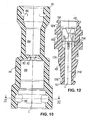
- the valve assembly 40 includes a two-part housing 42 having a base 44 (shown individually in FIGS. 10 and 11) having a first hydraulic port 46 and a male member 48 secured in the base 44 (shown in FIGS Fig. 12 shown separately), which forms a second hydraulic connection 50.
- the valve arrangement 40 is hydraulically connected to the master cylinder 12 via the first hydraulic connection 46, while the second hydraulic connection 50 serves for the hydraulic connection to the slave cylinder 14.
- the valve arrangement 40 can also be used rotated by 180 °, so that the first hydraulic connection 46 is connected to the slave cylinder 14, while the second hydraulic connection 50 is connected to the master cylinder 12.
- the valve assembly 40 further has two valve bodies 52, 54 received between the hydraulic ports 46, 50 in the housing 42, more specifically between the base 44 and the male portion 48 of the housing 42.
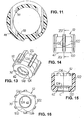
- the piston-like first valve body 52 (in FIGS. 13 to 16 shown individually) by means of a first spring element 56 in the form of a helical compression spring in a first direction, ie biased in FIGS. 2 to 7 down against a housing-fixed stop, by an upper, annular end surface 58 in these figures the insertion part 48 is formed.
- This basic or rest position of the first valve body 52 is shown in Figs. 2, 3, 6 and 7.
- the first valve body 52 has a central passage 60 for the hydraulic fluid and has on its second valve body 54 side facing a valve seat 62 for the second valve body 54th
- the plunger-like second valve body 54 (shown separately in Figs. 17 to 20) is connected by means of a second spring element 64 in the form of a helical compression spring in a second direction opposite the first direction, i. biased upwardly against the valve seat 62 on the first valve body 52 in Figs.
- a second spring element 64 in the form of a helical compression spring in a second direction opposite the first direction, i. biased upwardly against the valve seat 62 on the first valve body 52 in Figs.
- valve assembly 40 With regard to a flow through the valve assembly 40 in the second direction, ie from bottom to top in FIGS. 2 to 7, as can be seen in particular FIGS. 3, 5 and 7, between the first valve body 52 and the housing 42, More specifically, the outer periphery of the first valve body 52 and the inner periphery of the base 44 of the housing 42, a further passageway 66 formed for the hydraulic fluid. Furthermore, a further valve seat 68 is provided on the housing-fixed stop forming end face 58 against which the first valve body 52nd is biased by means of the first spring element 56. From FIGS.
- sealing surface of the valve seat 62 on the first valve body 52 and the sealing surface of the further valve seat 68 on the housing 42 are perpendicular to the direction of displacement of the first and second valve body 52, 54, and so on are arranged concentrically, that the sealing surfaces of the valve seats 62, 68 in the basic position of the valve assembly 40 (Fig. 2 and 3) lie in a plane.
- the further passageway 66 between the first valve body 52 and the housing 42 substantially - in so far as the first valve body 52 according to FIGS. 3 and 9 may be provided at its lower end face with a radially extending Ausretesnut 70 to allow in the case of a vacuum pressure filling of the hydraulic clutch actuator 10, the "pulling" of a vacuum in the hydraulic line 16. If, however, the return of the annular piston 26 in the slave cylinder 14 to a volume flow in the second direction, i.
- the first valve body 52 lifts against the force of the first spring element 56 from the further valve seat 68 on the insertion part 48 to open the further passageway 66 for a flow through the valve arrangement 40, while the second valve body 54 by means of the second Spring member 64 is pressed against the valve seat 62 on the first valve body 52.
- This condition is shown in Figs. 4 and 5.
- valve assembly 40 opens in the presence of a volume flow through the first hydraulic port 46 or in the presence of a volume flow through the second hydraulic port 50, without volume flow in contrast, due to the bias of the valve body 52, 54 by means of the spring elements 56, 64 closes in order to effect a separation of the liquid column for vibration decoupling.
- the first hydraulic connection 46 facing hydraulic active surface on the second valve body 54 and the spring force of the second spring member 64 on the one hand and the second hydraulic connection 50 facing hydraulic active surface on the first valve body 52 and the spring force of the first spring element 56 on the other hand are coordinated so that the opening pressure of the valve assembly 40, which may be, for example, 0.8 bar, in both directions of flow is approximately equal.
- the hydraulic active surfaces of the valve body and the spring forces of the spring elements but also be coordinated differently, so that the opening pressure of the valve assembly in the one flow direction of the opening pressure of the valve assembly is different in the other flow direction.
- the volume sensor 72 which is shown in greater detail in FIGS. 21 and 22, is a rubber-elastic, essentially coil-shaped element, which has a flow through it Volumeniller concerns 72 permitting through hole 74 has, with a central cylinder portion 76 and located on both sides of the cylinder portion 76 opening funnels 78.
- Outer circumference is the axis of symmetry with respect to its longitudinal axis L and with respect to an imaginary, perpendicular to the longitudinal axis L mirror symmetry trained Volumenaufillon 72 with a grooved annular recess 80, which according to FIGS. 2 to 7 together with the housing 42, more precisely the base part 44, delimits an annular air chamber 82 which extends upwards or downwards on both sides, ie in FIGS.
- valve arrangement 40 further details of the main components of the valve arrangement 40, namely the base part 44 of the housing 42 (FIGS. 10 and 11), the insertion part 48 of the housing 42 (FIG. 12), the first valve body 52 (FIGS. FIGS. 13 to 16) and the second valve body 54 (FIGS. 17 to 20), all of which are injection molded in the illustrated embodiment from a suitable plastic, such as a glass fiber reinforced PA 66 and accordingly each have substantially constant wall thicknesses and suitable Ausformschrägen.
- a suitable plastic such as a glass fiber reinforced PA 66 and accordingly each have substantially constant wall thicknesses and suitable Ausformschrägen.
- the base portion 44 of the housing 42 is provided, starting from both end faces, each with a stepped blind bore 86, 88, each terminating at a bottom 90 through which a central connecting bore 92 passes, which connects the blind holes 86, 88 together.
- the upper in Fig. 10 Blind hole 86 serves, as shown in FIGS. 2 to 7, on the one hand, the close receptacle of the Volumenaufillons 72 which rests according to Figures 2 to 7 on the upper side of the bottom 90.
- the base part 44 of the housing 42 is also provided in the region of the lower blind bore 88 near its end face with a slot 98 extending transversely to the longitudinal axis L, which is the receptacle of a shown embodiment also made of plastic, essentially U-shaped securing element 100 is used.
- the elastically auffederbare extending across the blind bore 88 securing element 100 analogous to the securing element 94 with a radial groove 102 on the outer circumference of the male part 48 together, the latter in the axial direction in the blind bore 88 of the base 44 to secure.
- the insertion part 48 is provided on the outer circumference with further radial grooves 104, 106, 108.
- the radial grooves 104 and 108 as shown in FIGS. 2 to 7, the recording of O-rings 110 and 112, of which the upper in FIGS. 2 to 7 O-ring 110, the connector of the housing 42, that seals from the base 44 and male member 48 to the outside.
- O-ring 112 By means of the bottom in FIGS. 2 to 7 O-ring 112 is a seal of a known plug connection to a receiving part (not shown), which is attached to the hydraulic line 16.
- the outer peripheral side provided with a plug terminal contour portion of the plug 48 is inserted, where he by means of a fuse element 94 corresponding fuse element (not shown), the in the radial groove 106 engages, can be secured against axial withdrawal.
- the male member 48 is provided with a stepped through-hole 114, in the first in Fig. 12 upper portion shown in FIGS. 2 to 7 from bottom to top, the second spring element 64 and then the second valve body 54 are added.
- the second spring element 64 is supported on webs 116 (see FIGS. 8 and 12) provided in a crosswise arrangement in the throughbore 114. Further, cross-shaped and with respect to the webs 116 by 45 ° angularly offset webs 118 (see again Fig. 8 and 12) center the second spring element 64 in the through hole 114th
- the first valve body 52 is formed substantially cup-shaped, with a bottom 120, on the front side of which the valve seat 62 is for the second valve body 54, and an outer wall 122 extending away from the bottom 120.
- the first spring element 56 extends into the first valve body 52, where it bears against the bottom 120 of the first valve body 52.
- the bottom 120 of the first valve body 52 is provided with a through hole 124, on the inner peripheral surface of the second valve body 54 is guided.
- first valve body 52 having a plurality of, provided in the illustrated embodiment, six evenly angularly spaced ribs 126 which are aligned in the axial direction.
- the crown-like on the side facing away from the bottom 120 in the axial direction on the outer wall 122 projecting ribs 126 serve to guide the first valve body 52 in the blind bore 88 of the base 44 of the housing 42 and limit together with the wall of the blind bore 88 in the housing 42 the other Passageway 66 in the valve assembly 40, as shown in Figs. 2 to 7 can be seen.
- the plunger-like second valve body 54 has a central plate portion 128, from which in Fig. 18 upwardly in the basic form a cylindrical centering projection 130 extends away for the second spring member 64, while in Fig. 18 down a in the basic form also cylindrical guide extension 132 connects to the plate portion 128.
- the guide projection 132 is - as well as the spigot 130 - provided on the outer peripheral side with a plurality of, in the illustrated embodiment, three extending in the longitudinal direction of the second valve body 54, uniformly angularly spaced and seen in cross-section round recesses 134, so that the guide projection 132 a number as in accordance with Fig. 20 star-shaped webs 136 has.
- the webs serve 136, as shown in FIGS. 2 to 7, the guide of the second valve body 54 in the through hole 124 in the bottom 120 of the first valve body 52 and limit together with the wall of the through hole 124 the (first) passage 60 for the Hydraulic fluid in the first valve body 52.
- a vibration isolation valve assembly including a housing housing two valve bodies, a first spring-biased in a reference direction against a housing-fixed stop and having a fluid passageway while the other is spring-biased in a reverse direction against a valve seat on the first valve body and lifts off from it at a volumetric flow in the reference direction to open the fluid passageway.
- a further fluid passageway is provided between the first valve body and the housing, wherein a further valve seat is formed against the housing-fixed stop against which the first valve body is spring-biased and lifts from the latter at a volume flow in the opposite direction to open the further fluid passageway.
Landscapes
- Engineering & Computer Science (AREA)
- General Engineering & Computer Science (AREA)
- Physics & Mathematics (AREA)
- Fluid Mechanics (AREA)
- Mechanical Engineering (AREA)
- Chemical & Material Sciences (AREA)
- Analytical Chemistry (AREA)
- Hydraulic Clutches, Magnetic Clutches, Fluid Clutches, And Fluid Joints (AREA)
Applications Claiming Priority (1)
| Application Number | Priority Date | Filing Date | Title |
|---|---|---|---|
| DE102005020853A DE102005020853B3 (de) | 2005-05-02 | 2005-05-02 | Zwischen einen Geber- und einen Nehmerzylinder eines hydraulischen Kraftübertragungssystems schaltbare Ventilanordnung zur Schwingungsentkopplung |
Publications (3)
| Publication Number | Publication Date |
|---|---|
| EP1719921A2 true EP1719921A2 (fr) | 2006-11-08 |
| EP1719921A3 EP1719921A3 (fr) | 2009-09-16 |
| EP1719921B1 EP1719921B1 (fr) | 2011-08-03 |
Family
ID=36709971
Family Applications (1)
| Application Number | Title | Priority Date | Filing Date |
|---|---|---|---|
| EP06006509A Expired - Lifetime EP1719921B1 (fr) | 2005-05-02 | 2006-03-29 | Assemblage de valves pour amortir les vibrations dans un système d'entraînement hydraulique comprenant un cylindre émetteur et un cylindre récepteur |
Country Status (3)
| Country | Link |
|---|---|
| US (1) | US7578378B2 (fr) |
| EP (1) | EP1719921B1 (fr) |
| DE (1) | DE102005020853B3 (fr) |
Cited By (2)
| Publication number | Priority date | Publication date | Assignee | Title |
|---|---|---|---|---|
| EP2211062A2 (fr) | 2009-01-22 | 2010-07-28 | FTE automotive GmbH | Cylindre récepteur pour un système de transmission d'énergie hydraulique à oscillations amorties, notamment un actionnement d'embrayage hydraulique pour véhicules automobiles |
| DE102009005830A1 (de) | 2009-01-22 | 2010-07-29 | Fte Automotive Gmbh | Vorrichtung zur Reduzierung von Druckpulsationen |
Families Citing this family (10)
| Publication number | Priority date | Publication date | Assignee | Title |
|---|---|---|---|---|
| EP1970590B1 (fr) | 2007-03-12 | 2013-10-02 | Schaeffler Technologies AG & Co. KG | Dispositif d'amortissement pour une trajectoire hydraulique en vue de l'actionnement d'un embrayage |
| DE102016003717A1 (de) * | 2016-03-31 | 2017-10-05 | Fte Automotive Gmbh | Vorrichtung zur Reduktion von Vibrationen in einem hydraulischen Betätigungssystem, insbesondere einer hydraulischen Kupplungsbetätigung für Kraftfahrzeuge |
| US10288093B2 (en) * | 2009-01-22 | 2019-05-14 | Fte Automotive Gmbh | Device for reducing vibrations in a hydraulic actuating system, particularly hydraulic clutch actuating system for motor vehicles |
| US9187967B2 (en) | 2011-12-14 | 2015-11-17 | 2M-Tek, Inc. | Fluid safety valve |
| WO2012100019A1 (fr) | 2011-01-21 | 2012-07-26 | 2M-Tek, Inc. | Dispositif et procédé pour descendre des tubulaires |
| CN104653649B (zh) * | 2015-02-09 | 2017-05-24 | 赖卫华 | 一种减震离合器 |
| US9708808B2 (en) * | 2015-05-21 | 2017-07-18 | Jay R. Smith Manufacturing Company | Trap primer |
| DE102015210366B3 (de) * | 2015-06-05 | 2016-11-10 | Schaeffler Technologies AG & Co. KG | Dämpfungselement für eine hydraulische Leitung |
| KR102461842B1 (ko) * | 2017-11-01 | 2022-11-01 | 현대자동차주식회사 | 클러치 작동기구용 레귤레이터 |
| CN114704561B (zh) * | 2022-04-27 | 2024-01-26 | 上海辛金路流体技术有限公司 | 钻机动力头同步离合器 |
Citations (2)
| Publication number | Priority date | Publication date | Assignee | Title |
|---|---|---|---|---|
| JPS5989834A (ja) | 1982-11-15 | 1984-05-24 | Rizumu Jidosha Buhin Seizo Kk | 液圧作動クラツチの防振装置 |
| DE19500908C1 (de) | 1995-01-13 | 1996-01-04 | Schaeffler Waelzlager Kg | Einrichtung zur Dämpfung von Schwingungen in Hydrauliksystemen |
Family Cites Families (22)
| Publication number | Priority date | Publication date | Assignee | Title |
|---|---|---|---|---|
| FR2106937A5 (fr) * | 1970-09-25 | 1972-05-05 | Maguet Rene | |
| US4006805A (en) * | 1975-06-30 | 1977-02-08 | Clark Equipment Company | Clutches with bypass inching valve |
| US4096882A (en) * | 1975-12-24 | 1978-06-27 | Kanzaki Kokyukoki Mfg. Co., Ltd. | Control valve |
| US5018352A (en) * | 1983-11-28 | 1991-05-28 | Automotive Products Plc | Modular prefilled hydraulic control apparatus |
| DE3627865A1 (de) * | 1986-04-12 | 1988-02-25 | Guenter Stein | Rueckschlagventil |
| US4976190A (en) * | 1989-03-28 | 1990-12-11 | Cooney Leo A | Hydraulic brake intensifier |
| US5655567A (en) * | 1995-06-07 | 1997-08-12 | Chrysler Corporation | Valve assembly for transmission |
| DE19540753C1 (de) * | 1995-11-02 | 1997-01-23 | Ebern Fahrzeugtech Gmbh | Verfahren zur Unterdrückung von Schwingungen eines Betätigungselements einer hydraulischen Kraftübertragungseinrichtung und Zusatzschwinger zur Durchführung des Verfahrens |
| DE19650734A1 (de) * | 1996-12-06 | 1998-06-10 | Schaeffler Waelzlager Ohg | Hydraulisches Betätigungssystem für eine Reibungskupplung mit integriertem Ventilelement |
| FR2762662B1 (fr) * | 1997-04-23 | 1999-05-28 | Valeo | Amortisseur de vibrations d'une pedale de debrayage pour vehicule automobile |
| US6196258B1 (en) * | 1998-04-16 | 2001-03-06 | Calsonic Corporation | Pressure control valve and evaporation fuel discharge control device |
| GB2354288B (en) * | 1999-09-15 | 2003-12-17 | Automotive Prod France | Hydraulic damper |
| JP2001280516A (ja) * | 2000-03-30 | 2001-10-10 | Denso Corp | 調圧弁 |
| JP3417928B2 (ja) * | 2000-04-26 | 2003-06-16 | 株式会社ナブコ | クラッチ作動装置 |
| US6216729B1 (en) * | 2000-05-08 | 2001-04-17 | Parsons & Whittemore, Inc. | Bidirectional check valve for hydraulic system |
| JP2001343032A (ja) * | 2000-06-01 | 2001-12-14 | Komatsu Ltd | クラッチ又はブレーキの流体圧力制御弁装置及び流体圧力制御方法 |
| DE10112674C1 (de) * | 2001-03-16 | 2002-02-14 | Fte Automotive Gmbh | Vorrichtung zur Reduzierung von Schwingungen in einem hydraulischen Kraftübertragungssystem |
| US6637271B1 (en) * | 2001-12-04 | 2003-10-28 | Automotive Products (Usa) Inc. | Method and apparatus for identifying and eliminating vibration symptoms in hydraulic clutch actuators |
| JP2004278639A (ja) * | 2003-03-14 | 2004-10-07 | Nabco Ltd | 脈動吸収装置およびクラッチマスタシリンダ |
| US7086388B2 (en) * | 2003-08-04 | 2006-08-08 | Delphi Technologies, Inc. | Combination valve for fuel system |
| JP2005083395A (ja) * | 2003-09-04 | 2005-03-31 | Nifco Inc | 圧力開閉弁 |
| ATE426109T1 (de) * | 2004-05-15 | 2009-04-15 | Luk Lamellen & Kupplungsbau | Hydraulische betatigungseinrichtung fur eine kupplung |
-
2005
- 2005-05-02 DE DE102005020853A patent/DE102005020853B3/de not_active Expired - Fee Related
-
2006
- 2006-03-29 EP EP06006509A patent/EP1719921B1/fr not_active Expired - Lifetime
- 2006-04-27 US US11/412,638 patent/US7578378B2/en active Active
Patent Citations (2)
| Publication number | Priority date | Publication date | Assignee | Title |
|---|---|---|---|---|
| JPS5989834A (ja) | 1982-11-15 | 1984-05-24 | Rizumu Jidosha Buhin Seizo Kk | 液圧作動クラツチの防振装置 |
| DE19500908C1 (de) | 1995-01-13 | 1996-01-04 | Schaeffler Waelzlager Kg | Einrichtung zur Dämpfung von Schwingungen in Hydrauliksystemen |
Cited By (6)
| Publication number | Priority date | Publication date | Assignee | Title |
|---|---|---|---|---|
| EP2211062A2 (fr) | 2009-01-22 | 2010-07-28 | FTE automotive GmbH | Cylindre récepteur pour un système de transmission d'énergie hydraulique à oscillations amorties, notamment un actionnement d'embrayage hydraulique pour véhicules automobiles |
| DE102009005830A1 (de) | 2009-01-22 | 2010-07-29 | Fte Automotive Gmbh | Vorrichtung zur Reduzierung von Druckpulsationen |
| WO2010084008A1 (fr) | 2009-01-22 | 2010-07-29 | Fte Automotive Gmbh | Dispositif de réduction des impulsions de pression |
| DE102009005828A1 (de) | 2009-01-22 | 2010-07-29 | Fte Automotive Gmbh | Nehmerzylinder für ein schwingungsgedämpftes hydraulisches Kraftübertragungssystem, insbesondere eine hydraulische Kupplungsbetätigung für Kraftfahrzeuge |
| EP2455621A1 (fr) | 2009-01-22 | 2012-05-23 | FTE automotive GmbH | Dispositif de réduction des pulsations de pression |
| JP2012515886A (ja) * | 2009-01-22 | 2012-07-12 | エフテーエー・オートモーティブ・ゲーエムベーハー | 圧力の脈動を減じるための装置 |
Also Published As
| Publication number | Publication date |
|---|---|
| DE102005020853B3 (de) | 2006-08-10 |
| US20060243552A1 (en) | 2006-11-02 |
| EP1719921B1 (fr) | 2011-08-03 |
| US7578378B2 (en) | 2009-08-25 |
| EP1719921A3 (fr) | 2009-09-16 |
Similar Documents
| Publication | Publication Date | Title |
|---|---|---|
| EP2455621B1 (fr) | Dispositif de réduction des pulsations de pression | |
| EP2211062B1 (fr) | Cylindre récepteur pour un système de transmission d'énergie hydraulique à oscillations amorties, notamment un actionnement d'embrayage hydraulique pour véhicules automobiles | |
| DE69718236T2 (de) | Flüssigkeitsgefülltes,elastisches Lager mit Öffnungsdurchlässen die so eingestellt sind,dass Empfangs-Schwingungen von jeweiligen verschiedenen Frequenzfeldern gedämpft werden | |
| EP3314145B1 (fr) | Agencement de soupape d'amortissement dépendant de la fréquence | |
| EP1719921B1 (fr) | Assemblage de valves pour amortir les vibrations dans un système d'entraînement hydraulique comprenant un cylindre émetteur et un cylindre récepteur | |
| EP1020936B1 (fr) | Organe de réglage comportant un actionneur à longueur réglable | |
| DE19880667B4 (de) | Schwingungsdämpfer eines Kupplungspedals für Kraftfahrzeuge | |
| DE102008003991A1 (de) | Anordnung zur Unterdrückung von Eigen-Resonanzen in einer hydraulischen Strecke | |
| DE112008000113B4 (de) | Kupplungsbetätigungsvorrichtung mit einer Anordnung zur Unterdrückung von Eigen-Resonanzen | |
| DE102014210702A1 (de) | Frequenzabhängige Dämpfventilanordnung | |
| EP3817957B1 (fr) | Dispositif d'amortissement de système de freinage | |
| DE19807446B4 (de) | Dämpfungsglied für hydraulische Verstelleinrichtungen bei Kraftfahrzeugen | |
| EP1241394A2 (fr) | Dispositif pour la réduction des vibrations dans un système hydraulique de transmission de puissance | |
| EP1666752A2 (fr) | Cylindre hydraulique, en particulier cylindre émetteur pour actionnement hydraulique d'embrayage de véhicules | |
| DE102016003717A1 (de) | Vorrichtung zur Reduktion von Vibrationen in einem hydraulischen Betätigungssystem, insbesondere einer hydraulischen Kupplungsbetätigung für Kraftfahrzeuge | |
| EP1637793B1 (fr) | Actionneur hydraulique avec amortisseur de vibrations | |
| EP1651859B1 (fr) | Coupleur hydraulique et soupape d'injection de carburant | |
| WO2015022135A1 (fr) | Ensemble à soupapes | |
| EP1666753A2 (fr) | Cylindre hydraulique, en particulier cylindre émetteur pour actionnement hydraulique d'embrayage de véhicules | |
| WO2021001078A1 (fr) | Dispositif d'amortissement de système de freinage présentant une chambre supplémentaire | |
| EP1099062A1 (fr) | Support de moteur a deux chambres a amortissement hydraulique | |
| EP1600319B1 (fr) | Dispositif d'actionnement hydraulique pour embrayage de véhicule. | |
| DE602004004629T2 (de) | Hydraulisches Kraftübertragungssystem mit einer Vorrichtung zur Schwingungsreduzierung und mit einem solchen System versehenes Fahrzeug | |
| DE10343488A1 (de) | Hydrauliksystem mit Ausgleichsspeicher | |
| DE102019201939A1 (de) | Bremssystemdämpfvorrichtung |
Legal Events
| Date | Code | Title | Description |
|---|---|---|---|
| PUAI | Public reference made under article 153(3) epc to a published international application that has entered the european phase |
Free format text: ORIGINAL CODE: 0009012 |
|
| AK | Designated contracting states |
Kind code of ref document: A2 Designated state(s): AT BE BG CH CY CZ DE DK EE ES FI FR GB GR HU IE IS IT LI LT LU LV MC NL PL PT RO SE SI SK TR |
|
| AX | Request for extension of the european patent |
Extension state: AL BA HR MK YU |
|
| PUAL | Search report despatched |
Free format text: ORIGINAL CODE: 0009013 |
|
| AK | Designated contracting states |
Kind code of ref document: A3 Designated state(s): AT BE BG CH CY CZ DE DK EE ES FI FR GB GR HU IE IS IT LI LT LU LV MC NL PL PT RO SE SI SK TR |
|
| AX | Request for extension of the european patent |
Extension state: AL BA HR MK YU |
|
| 17P | Request for examination filed |
Effective date: 20090903 |
|
| AKX | Designation fees paid |
Designated state(s): DE FR GB IT |
|
| GRAP | Despatch of communication of intention to grant a patent |
Free format text: ORIGINAL CODE: EPIDOSNIGR1 |
|
| GRAS | Grant fee paid |
Free format text: ORIGINAL CODE: EPIDOSNIGR3 |
|
| GRAA | (expected) grant |
Free format text: ORIGINAL CODE: 0009210 |
|
| AK | Designated contracting states |
Kind code of ref document: B1 Designated state(s): DE FR GB IT |
|
| REG | Reference to a national code |
Ref country code: GB Ref legal event code: FG4D Free format text: NOT ENGLISH |
|
| REG | Reference to a national code |
Ref country code: DE Ref legal event code: R096 Ref document number: 502006009940 Country of ref document: DE Effective date: 20110929 |
|
| PLBE | No opposition filed within time limit |
Free format text: ORIGINAL CODE: 0009261 |
|
| STAA | Information on the status of an ep patent application or granted ep patent |
Free format text: STATUS: NO OPPOSITION FILED WITHIN TIME LIMIT |
|
| 26N | No opposition filed |
Effective date: 20120504 |
|
| REG | Reference to a national code |
Ref country code: DE Ref legal event code: R097 Ref document number: 502006009940 Country of ref document: DE Effective date: 20120504 |
|
| REG | Reference to a national code |
Ref country code: FR Ref legal event code: PLFP Year of fee payment: 11 |
|
| REG | Reference to a national code |
Ref country code: FR Ref legal event code: PLFP Year of fee payment: 12 |
|
| REG | Reference to a national code |
Ref country code: FR Ref legal event code: PLFP Year of fee payment: 13 |
|
| PGFP | Annual fee paid to national office [announced via postgrant information from national office to epo] |
Ref country code: IT Payment date: 20180319 Year of fee payment: 13 |
|
| PGFP | Annual fee paid to national office [announced via postgrant information from national office to epo] |
Ref country code: GB Payment date: 20180430 Year of fee payment: 13 |
|
| GBPC | Gb: european patent ceased through non-payment of renewal fee |
Effective date: 20190329 |
|
| PG25 | Lapsed in a contracting state [announced via postgrant information from national office to epo] |
Ref country code: GB Free format text: LAPSE BECAUSE OF NON-PAYMENT OF DUE FEES Effective date: 20190329 |
|
| PG25 | Lapsed in a contracting state [announced via postgrant information from national office to epo] |
Ref country code: IT Free format text: LAPSE BECAUSE OF NON-PAYMENT OF DUE FEES Effective date: 20190329 |
|
| P01 | Opt-out of the competence of the unified patent court (upc) registered |
Effective date: 20230629 |
|
| REG | Reference to a national code |
Ref country code: DE Ref legal event code: R081 Ref document number: 502006009940 Country of ref document: DE Owner name: VALEO POWERTRAIN GMBH, DE Free format text: FORMER OWNER: FTE ASIA GMBH, 96106 EBERN, DE Ref country code: DE Ref legal event code: R081 Ref document number: 502006009940 Country of ref document: DE Owner name: VALEO POWERTRAIN GMBH, DE Free format text: FORMER OWNER: FTE AUTOMOTIVE GMBH, 96106 EBERN, DE Ref country code: DE Ref legal event code: R082 Ref document number: 502006009940 Country of ref document: DE Representative=s name: OPPERMANN, MARK, DIPL.-ING., DE |
|
| PGFP | Annual fee paid to national office [announced via postgrant information from national office to epo] |
Ref country code: DE Payment date: 20250313 Year of fee payment: 20 |
|
| PGFP | Annual fee paid to national office [announced via postgrant information from national office to epo] |
Ref country code: FR Payment date: 20250331 Year of fee payment: 20 |
|
| REG | Reference to a national code |
Ref country code: DE Ref legal event code: R071 Ref document number: 502006009940 Country of ref document: DE |