EP1666753A2 - Cylindre hydraulique, en particulier cylindre émetteur pour actionnement hydraulique d'embrayage de véhicules - Google Patents
Cylindre hydraulique, en particulier cylindre émetteur pour actionnement hydraulique d'embrayage de véhicules Download PDFInfo
- Publication number
- EP1666753A2 EP1666753A2 EP05025937A EP05025937A EP1666753A2 EP 1666753 A2 EP1666753 A2 EP 1666753A2 EP 05025937 A EP05025937 A EP 05025937A EP 05025937 A EP05025937 A EP 05025937A EP 1666753 A2 EP1666753 A2 EP 1666753A2
- Authority
- EP
- European Patent Office
- Prior art keywords
- cylinder
- piston
- hydraulic cylinder
- pressure
- pressure chamber
- Prior art date
- Legal status (The legal status is an assumption and is not a legal conclusion. Google has not performed a legal analysis and makes no representation as to the accuracy of the status listed.)
- Granted
Links
Images


Classifications
-
- F—MECHANICAL ENGINEERING; LIGHTING; HEATING; WEAPONS; BLASTING
- F16—ENGINEERING ELEMENTS AND UNITS; GENERAL MEASURES FOR PRODUCING AND MAINTAINING EFFECTIVE FUNCTIONING OF MACHINES OR INSTALLATIONS; THERMAL INSULATION IN GENERAL
- F16D—COUPLINGS FOR TRANSMITTING ROTATION; CLUTCHES; BRAKES
- F16D23/00—Details of mechanically-actuated clutches not specific for one distinct type
- F16D23/12—Mechanical clutch-actuating mechanisms arranged outside the clutch as such
Definitions
- the invention relates to a hydraulic cylinder according to the preamble of claim 1.
- the invention relates to a slave cylinder for a hydraulic clutch actuation for motor vehicles, as they are used in masses in the automotive industry.
- a conventional hydraulic clutch actuator for motor vehicles has a master cylinder connected to a reservoir filled with hydraulic fluid.
- the master cylinder has a cylinder housing, in the housing bore a piston is received longitudinally displaceable.
- the master cylinder piston bounded in the housing bore of the cylinder housing a pressure chamber and can be mechanically acted upon by means of a clutch pedal or an electric motor drive with an actuating force.
- the pressure chamber of the master cylinder is hydraulically connected via a pressure line to a pressure chamber of a slave cylinder, so that the pressure generated by depressing the clutch pedal or electromotive displacement of the master cylinder piston in the pressure chamber of the master cylinder via the liquid column in the pressure line to the pressure chamber of the slave cylinder is transferable.
- the slave cylinder also has a cylinder housing with a housing bore in which a pressure chamber of the slave cylinder limiting and thus acted upon by the pressure generated in the master cylinder piston is taken longitudinally displaceable.
- the slave cylinder piston is associated with a piston rod which acts on a clutch lever, which in turn with the release bearing of the clutch in operative connection stands.
- a generic slave cylinder for a hydraulic clutch actuation for motor vehicles is known from DE 43 22 969 A1.
- This slave cylinder has a pressure chamber which is delimited on one side by a piston which is received longitudinally displaceably in a cylinder housing.
- the pressure space of a housing bottom of the cylinder housing is limited, and radially outward from a peripheral wall of the cylinder housing, which is formed by an inserted in a housing base tube part.
- the pressure chamber can optionally be acted upon via a provided on the housing bottom pressure port with a pressure medium.
- a further connection for a breather is also provided on the housing bottom, which serves to vent the slave cylinder after its assembly and filling with the pressure medium, ie dissipate any air bubbles or bubbles in the pressure medium to the outside.
- the breather port opens here near the central axis of the cylinder housing in the pressure chamber, which causes air that has accumulated or accumulated in the installed position of the slave cylinder at the top of the peripheral wall of the cylinder housing, is difficult to dissipate to the outside, especially one in the pressure chamber arranged helical compression spring for the piston return hinders the vent.
- the Entlmediaeranschluß requires in the production of the slave cylinder a significant overhead, which is generally undesirable in the mass production of such cylinder.
- the invention has for its object to provide a simple as possible and compact hydraulic cylinder, in particular slave cylinder for a hydraulic clutch actuation for motor vehicles, which can be compared to the generic state of the art simpler way vented.
- a hydraulic cylinder in particular slave cylinder for a hydraulic clutch actuator for motor vehicles, which has a pressure chamber on one side of a longitudinally displaceable in a cylinder housing piston, on the other side of a housing bottom of the cylinder housing and radially outward of a peripheral wall of the cylinder housing is limited, wherein the pressure chamber is selectively acted upon by a pressure medium provided on the housing bottom with a pressure medium to move the piston in the cylinder housing, inserted into the pressure port an insert having a communicating with the pressure port channel portion which is located in the mounting position of the hydraulic cylinder extends substantially in the vertical direction and opens in the vicinity of the peripheral wall of the cylinder housing in the pressure chamber.
- the simple inserted into the existing existing pressure port insert provides with its opening in an upper region of the pressure chamber channel section for a special rinsing effect in the pressure chamber, especially in the hydraulic relief of the hydraulic cylinder, ie during the piston return, which rinsing effect a continuous, automatic venting of the hydraulic cylinder Operation guaranteed.
- Special breather connections or the like. are dispensable, which alone leads to space advantages. Other effects and Advantages of the invention will become apparent from the detailed description of a preferred embodiment.
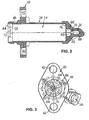
- Fig. 1 shows a slave cylinder 10 for a hydraulic clutch actuation for motor vehicles exemplarily for a hydraulic cylinder designed according to the invention.
- the slave cylinder 10 has a generally numbered 12 cylinder housing in which a piston assembly 14 is received longitudinally displaceable, which comprises a piston 16 and a at least tension and compression-resistant manner connected to the piston 16 piston rod 18.
- a pressure chamber 20 fixed on the left in Fig. 1 side variable of the piston 16, on the right in Fig. 1 right side of a housing bottom 22 of the cylinder housing 12 and radially outwardly fixed by a peripheral wall 24 of the Cylinder housing 12 is limited.
- the pressure chamber 20 is optionally a provided on the housing bottom 22 pressure port 26, which is connected in the assembled state of the slave cylinder 10 in a conventional manner via a pressure line, not shown, to a clutch master cylinder, also not shown, acted upon by a pressure medium, such as brake fluid to move the piston 16 in the cylinder housing 12.
- a spring element in the form of a helical compression spring 28 is provided, which is supported at its right in Fig. 1 end to the cylinder housing 12 and engages with its left in Fig.
- Fig. 1 end to the piston rod 18 so that the helical compression spring 28 biases the piston assembly 14 in a direction away from the housing bottom 22 to hold the piston rod 18 in the assembled state of the slave cylinder 10 in contact with a schematically drawn in Fig. 1 clutch lever 30.
- an insert 32 is provided in the pressure chamber 20 on the housing bottom 22, more precisely used in the pressure port 26 in the housing bottom 22, which advantageously performs several functions in the illustrated embodiment.
- the insert 32 serves as a fixing element which fixes the piston assembly 14 prior to a first actuation of the slave cylinder 10 in a predetermined stroke position with respect to the cylinder housing 12 and is adapted to release the piston assembly 14 with respect to the cylinder housing 12 with the first actuation of the slave cylinder 10 , wherein the insert part 32 for releasable fixing of the piston assembly 14 with respect to the cylinder housing 12 with a counter-element on the piston 16, here in the form of an extension 34, cooperates.
- the insert member 32 serves as a kind of deaerator for the pressure chamber 20, to which it has a communicating with the pressure port 26 channel portion 36 which extends in the mounting position shown in Fig. 1 of the slave cylinder 10 substantially in the vertical direction and in the vicinity the peripheral wall 24 of the cylinder housing 12 in the pressure chamber 20 opens.
- the cylinder housing 12 has a main body 38 which is preferably injection-molded from plastic and which is shown separately in FIG. 2.
- a mounting flange 40 for mounting the slave cylinder 10 in the motor vehicle having two mounting holes 42 which are reinforced according to FIG. 1 by means of slotted steel bushes 44. Due to the fastening bores 42 lined with the steel bushes 44, in the assembled state of the slave cylinder 10, e.g. Screws (not shown) through which serve the attachment of the slave cylinder 10 at about a transmission wall (not shown) in the motor vehicle.
- 1 and 2 left of the mounting flange 40 of the main body 38 of the cylinder housing 12 has further outer peripheral side a radial groove 46, in the FIG. 1, a the piston rod 18 surrounding bellows portion 48 having elastomeric protective cap 50 is knotted with an inner circumferential side annular collar 52 is.
- the inner circumference of the base body 38 of the cylinder housing 12 has a in Fig. 2 to the left open stepped bore 54, in accordance with FIG. 1, a preferably metallic barrel 56 is used as a further component of the cylinder housing 12.
- the sleeve 56 has two hollow cylindrical sleeve portions 58, 60 of different diameters, which are connected to each other at the bottom 22 of the cylinder housing 12 via a ring portion 62.
- the bore 54 of the body 38 now has four sections 64, 66, 68 and 70 of different diameters, which decreases in Figs. 1 and 2 from left to right.
- the first bore portion 64 has at its open end an undercut 72 which serves to define an annular, slotted for mounting securing element 74 preferably plastic on the cylinder housing 12 which abuts the left in Fig. 1 face of the barrel 56 and thus the Running sleeve 56 in the main body 38 of the cylinder housing 12 secures.
- the second bore portion 66 of the stepped bore 54 of the base body 38 of the larger diameter sleeve portion 58 of the barrel sleeve 56 is tightly received, which forms the pressure chamber 20 bounding peripheral wall 24 with its inner peripheral surface.
- the third bore section 68 adjoins the second bore section 66 via an annular shoulder 76 against which the annular section 62 of the running sleeve 56 abuts.
- the sleeve portion 60 is provided on the outer peripheral side with a radial groove 78 for receiving an O-ring 80, which provides a static seal between the third bore portion 68 and the sleeve portion 60.
- the fourth bore section 70 of the stepped bore 54 in the base body 38 is provided on the inner peripheral side with a plurality of longitudinal ribs 86 extending in the axial direction of the cylinder housing 12 in the illustrated embodiment protrude inwardly, unevenly or asymmetrically over the circumference of the fourth bore portion 70 are distributed and serve a rotational angle orientation of the insert member 32 in the pressure port 26, as will also be explained in more detail below.
- a base body 38 finally opens, smaller diameter pressure port bore 88 in the fourth bore portion 70th
- the fourth bore portion 70 of the stepped bore 54 has a smaller diameter than the third bore portion 68, so that the base body 38 of the cylinder housing 12 in this area substantially following the outer contour of the base body 38 does not have excessively large differences in wall thickness, If the outer contour of the main body 38 is changed, the fourth bore section 70 could in principle also be formed with a diameter which corresponds to the diameter of the third bore section 68.
- the pressure port bore 88, the fourth bore portion 70 of the stepped bore 54 and the sleeve portion 60 of the barrel 56 accommodated in the third bore portion 68 are part of the pressure port 26, via which the pressure chamber 20 can be acted upon by the pressure medium .
- the pressure port 26 As a result of the effect caused by the O-ring 80 static seal on the outer circumference of the smaller diameter sleeve portion 60 of the barrel 56 this undergoes pressurization of the pressure chamber 20 via the pressure port 26, wherein the hydraulic pressure on the annular end face 84 of the sleeve portion 60 and the another on the surface of this larger, the pressure chamber 20 facing end face of the annular portion 62 of the sleeve 56 acts, a resultant force to the right in Fig. 1, which tends to keep the sleeve 56 in the stepped bore 54 of the body 38, the attachment the running sleeve 56 in the main body 38 thus relieved by means of the securing element 74.
- Fig. 1 of the further which has a small radial clearance in the larger diameter sleeve portion 58th the running sleeve 56 of the cylinder housing 12 guided, in the illustrated embodiment metallic piston 16 on the outer circumference of a radial groove 90 for receiving a Nutrings 92.
- the elastomeric groove ring 92 is in a conventional manner with its outer peripheral side sealing lip under a certain bias on the peripheral wall 24 of the cylinder housing 12 and thus provides for a dynamic sealing of the pressure chamber 20 to the left in Fig. 1st
- a central recess 94 in which a at the right in Fig. 1 end of the piston rod 18 formed ball head 96 is pivotally held by a securing element 98, so that the piston rod 18 with respect the piston 16 has a certain angular mobility.
- this could also be integrally formed with a piston rod conically or spherically sloping piston outer surface to ensure the angular mobility, as in principle from DE 43 22 969 A1 or DE 43 31 241 A1 is known.
- the metallic piston rod 18 in the illustrated embodiment has on the left in Fig. 1 side a thickened end 100 having a substantially spherical end surface 102, via which the piston rod 18 operatively acts on the clutch lever 30.
- the piston rod 18 further comprises a collar 104, which serves to connect the protective cap 50 to the piston rod 18, wherein the annular collar 104 of the piston rod 18 positively in a substantially complementary shaped annular recess 106 in a mounting portion 108 of Protective cap 50 engages, which adjoins the bellows portion 48 of the protective cap 50 on the side facing away from the pressure chamber 20 side of the protective cap 50.
- annular collar 104 of the piston rod 18 with its the pressure chamber 20 facing end face an abutment for the helical compression spring 28, wherein from the annular collar 104 facing the end of the helical compression spring 28 and a certain radial centering for the piston rod 18 emanates, which is advantageous in the assembly of the slave cylinder 10 in the vehicle.
- the securing element 74 is provided for holding the running sleeve 56 in the cylinder housing 12 on its side facing away from the pressure chamber 20 side with an axial groove 110, which as another abutment and for centering of the pressure chamber 20 facing, in FIG 1 right end of the helical compression spring 28 is used, which widens in diameter, starting from the annular collar 104 to the axial groove 110 toward substantially conical, that is formed frusto-conical.
- FIGS. 4 to 9 show further details of the insert part 32, which is preferably injection-molded from a plastic, such as polyamide 66 with a glass fiber reinforcement, which according to FIG. 8 in particular is formed in all its areas with a substantially constant wall thickness and thus to avoid insufficient dimensional stability due to accumulation of material.
- a plastic such as polyamide 66 with a glass fiber reinforcement
- the insert 32 builds on a flat base plate 112 with plane-parallel end faces, of which the right in Fig. 5 end face in the mounted state of the insert member 32 abuts the pressure chamber 20 facing end side of the annular portion 62 of the barrel 56.
- the insert member 32 On the base plate 112, three functional portions of the insert member 32 are arranged, namely on the side remote from the pressure chamber 20 side of the base plate 112, a mounting portion 114 for attachment of the insert 32 in the pressure port 26, on the pressure chamber 20 side facing the base plate 112 a tether portion 116 to releasably Fixation of the piston assembly 14 with respect to the cylinder housing 12 and, also on the side facing the pressure chamber 20 side of the base plate 112, the channel description already mentioned at the beginning of the description of the figures for venting the pressure chamber 20th
- the insert member 32 is mounted by means of a snap connection in the pressure port 26.
- the substantially hollow cylindrical mounting portion 114 is provided at its side facing away from the base plate 112, the free end outer peripheral side with a segmented annular collar 118, the base plate 112 facing end face forms a substantially annular, segmented abutment surface 120.
- the fastening portion 114 of the further to form spring arms 122 a plurality of, in the illustrated embodiment four in the longitudinal direction of the mounting portion 114 extending slots 124 whose asymmetrical distribution over the circumference of the mounting portion 114 (see FIG.
- the distribution of the longitudinal ribs 86 in the fourth bore portion 70 of the stepped bore 54 in the base body 38 of the cylinder housing 12 corresponds.
- the slots 124 in the mounting portion 114 of the insert member 32 on the one hand and the longitudinal ribs 86 in the base body 38 of the cylinder housing 12 on the other hand dimensionally matched to one another that engage in the mounted state of the insert member 32, the longitudinal ribs 86 with a small circumferential clearance in the slots 124, but not radially inwardly over the spring arms 122 protrude.
- the asymmetrical, coordinated circumferential distribution of the longitudinal ribs 86 / slots 124 provides a simple way for a clear rotational angle orientation of the mounted insert 32 in the slave cylinder 10, namely such that the channel portion 36 is aligned on the insert member 32 in a vertical upward direction, as shown in FIG. 1 shown.
- this is positively fixed in the slave cylinder 10 in the axial direction, the abutment surface 120 on the annular collar 118 of the mounting portion 114 of FIG. 1 over the fourth bore portion 70 of the stepped bore 54 in the main body 38 radially inwardly projecting, annular end face 84 of the smaller diameter sleeve portion 60 of the barrel 56 engages snap-hook-like in the cylinder housing 12.
- the latter is inserted starting from the open end of the barrel sleeve 56 lined cylinder housing 12 in the barrel 56 to the spring arms 122 of the mounting portion 114 at a small slope between the ring portion 62 and the inner circumference of the smaller diameter sleeve portion 60 of the sleeve 56 come to rest.
- the spring arms 122 spring radially inward.
- the longitudinal ribs 86 thread in the fourth bore portion 70 of the main body 38 of the cylinder housing 12 in the slots 124 of the attachment portion 114th of the insert 32 before the spring arms 122 rebound radially outward again and latch with their segmented abutment surface 120 behind the annular end face 84 of the sleeve portion 60.
- the base plate 112 of the insert 32 comes with its the pressure port 26 facing end side of the pressure chamber 20 facing end face of the annular portion 62 of the barrel 56 to the plant.
- the facing end surfaces on the spring arms 122 on the one hand and the longitudinal ribs 86 on the other hand substantially flat against each other and thus prevent further axial displacement of the insert 32 with respect to the cylinder housing 12th Since, moreover, the angular orientation of the insert 32 with respect to the cylinder housing 12 takes place on the base body 38, a circumferential fixing of the running sleeve 56 in the base body 38 is not required.
- the fastening section 114 delimits on the inner peripheral side a cylindrical, aligned with the central axis M of the slave cylinder 10 channel portion 126 which passes through the base plate 112 of the insert 32.
- the channel sections 36 and 126 intersect, so that a substantially rectangular passage between the pressure chamber 20 and the pressure port 26 is.
- the vertically extending ends Channel section 36 just before the peripheral wall 24 of the cylinder housing 12 in the pressure chamber 20th
- any air pockets or bubbles collect in the pressure medium 20 located in the pressure medium above the pressure chamber 20.
- heated hydraulic fluid in the pressure chamber 20 rises upwards in the pressure chamber 20.
- the piston 16 In a return of the piston 16 from an actuating position to its basic position shown in Fig. 1, there is a directional forced flow through the channel sections 36 and 126 via the pressure port 26 and the pressure line, not shown, to the clutch master cylinder, also not shown, in turn with a not As shown already connected reservoir shown is connected.
- the insert 32 provides with its vertically extending channel portion 36 for a continuous and safe self-venting of the slave cylinder 10 and a discharge of heated hydraulic fluid, which additional breather connections or the like. dispensable.
- the tether portion 116 of the insert 32 has an attached to the base plate 112, in the mounted state of the insert 32 according to FIG. 1 with the center axis M of the slave cylinder 10 axially aligned hollow cylinder 128, which according to FIGS. 1 and 8 laterally of the channel section 36 is broken.
- the hollow cylinder 128 is provided on the inner peripheral side with a circumferential, radially inwardly projecting annular bead 130, which is shown enlarged in FIG.
- the torus acts 130 with the pressure chamber-side extension 34 of the piston 16, more precisely with an end remote from the piston 16 of the extension 34 on the outer peripheral side integrally formed annular collar 132 (Fig. 1) together, which has a slightly tapered to the pressure port 26 outer surface.
- the slave cylinder 10 since the piston assembly 14 is tied in a position in which they as far as possible in the cylinder housing 12th pushed in, the slave cylinder 10 required during storage, transport and installation in the vehicle only a small space.
- the slave cylinder 10 can be mounted substantially force-free in the vehicle, because the helical compression spring 28 does not have to be compressed, but is held by means of the insert 32 caused binding of the piston assembly 14 in a biased position.
- the pressure medium is supplied via the pressure connection 26 to the pressure chamber 20.
- the piston 16 experiences a in Fig. 1 to the left directed force, which adds up to the force of the helical compression spring 28. If the sum of these forces exceeds the holding force of the connection between the projection 34 of the piston 16 and the tether portion 116 of the insert 32, the annular bead 130 on the tether portion 116 is widened again via the annular collar 132 on the extension 34, whereupon the piston assembly 14 is released from the insert 32.
- a further binding of the piston assembly 14 during operation of the slave cylinder 10 is not provided and can not be done because the distance shown in Fig. 1 between the extension 34 on the piston 16 and the tether portion 116 on the insert part 32 during operation of the slave cylinder 10 is no longer below becomes.
- the holding force of the connection between the extension 34 of the piston 16 and the tether portion 116 of the insert member 32 is designed constructively such that it is on the one hand sufficiently larger than the spring force of the helical compression spring 28 to unintentional release of the bondage the piston assembly 14 to prevent, on the other hand, but sufficiently smaller than the holding force of the connection between the insert member 32 and the cylinder housing 12, so that the insert member 32 is not drawn out of the pressure port 26 at the first actuation of the slave cylinder 10.
- this positive connection can also be configured differently, such as with spring arms and snap hook thereon as a shackle portion of the insert, analogous to the above-described determination of the insert in the pressure port.
- a hydraulic cylinder having a pressure chamber which is delimited on one side by a longitudinally displaceable in a cylinder housing piston, on the other side of a housing bottom of the cylinder housing and radially outwardly from a peripheral wall of the cylinder housing, wherein the pressure chamber optionally can be acted upon by a provided on the housing bottom pressure port with a pressure medium to move the piston in the cylinder housing.
- an insert part is used in the pressure connection, which has a communicating with the pressure port channel portion which extends in the installed position of the hydraulic cylinder in a substantially vertical direction and opens in the vicinity of the peripheral wall of the cylinder housing in the pressure chamber.
Landscapes
- Engineering & Computer Science (AREA)
- General Engineering & Computer Science (AREA)
- Mechanical Engineering (AREA)
- Hydraulic Clutches, Magnetic Clutches, Fluid Clutches, And Fluid Joints (AREA)
Applications Claiming Priority (1)
| Application Number | Priority Date | Filing Date | Title |
|---|---|---|---|
| DE102004058610A DE102004058610A1 (de) | 2004-12-03 | 2004-12-03 | Hydraulikzylinder, insbesondere Nehmerzylinder für eine hydraulische Kupplungsbetätigung für Kraftfahrzeuge |
Publications (3)
| Publication Number | Publication Date |
|---|---|
| EP1666753A2 true EP1666753A2 (fr) | 2006-06-07 |
| EP1666753A3 EP1666753A3 (fr) | 2007-04-04 |
| EP1666753B1 EP1666753B1 (fr) | 2008-10-22 |
Family
ID=35478345
Family Applications (1)
| Application Number | Title | Priority Date | Filing Date |
|---|---|---|---|
| EP05025937A Expired - Lifetime EP1666753B1 (fr) | 2004-12-03 | 2005-11-29 | Cylindre hydraulique, en particulier cylindre émetteur pour actionnement hydraulique d'embrayage de véhicules |
Country Status (3)
| Country | Link |
|---|---|
| US (1) | US7493849B2 (fr) |
| EP (1) | EP1666753B1 (fr) |
| DE (2) | DE102004058610A1 (fr) |
Cited By (1)
| Publication number | Priority date | Publication date | Assignee | Title |
|---|---|---|---|---|
| WO2012000786A1 (fr) * | 2010-07-02 | 2012-01-05 | Schaeffler Technologies Gmbh & Co. Kg | Dispositif permettant de modifier la position angulaire relative d'un arbre à cames par rapport à un vilebrequin d'un moteur à combustion interne |
Families Citing this family (4)
| Publication number | Priority date | Publication date | Assignee | Title |
|---|---|---|---|---|
| US8695863B2 (en) * | 2011-05-10 | 2014-04-15 | Illinois Tool Works, Inc. | Reinforced plastic sleeve for pneumatic nailer |
| KR102023143B1 (ko) * | 2012-11-08 | 2019-09-19 | 술저 믹스팩 아게 | 2개 이상의 유동성 성분을 위한 카트리지 |
| DE102016218183A1 (de) * | 2016-09-06 | 2018-03-08 | Continental Teves Ag & Co. Ohg | Bremsgerät für eine hydraulische Kraftfahrzeugbremsanlage |
| CN110268179B (zh) * | 2017-02-10 | 2021-10-08 | 舍弗勒技术股份两合公司 | 用于离合器的操纵装置和制造方法 |
Family Cites Families (12)
| Publication number | Priority date | Publication date | Assignee | Title |
|---|---|---|---|---|
| GB1223333A (en) * | 1967-04-19 | 1971-02-24 | Daikin Mfg Co Ltd | Improvements in or relating to apparatus for automatically adjusting the clearance of a motor vehicle clutch |
| US4162616A (en) * | 1976-04-02 | 1979-07-31 | Tokico Ltd. | Hydraulic master cylinder |
| JPS586015U (ja) * | 1981-04-30 | 1983-01-14 | オ−トモ−チブ・プロダクツ・ピ−エルシ− | 制御バルブ |
| US4785721A (en) * | 1986-07-15 | 1988-11-22 | Leigh Monstevens Keith V | Hydraulic cylinder annular insert for retainer member |
| DE4322969C2 (de) * | 1993-07-09 | 2002-03-14 | Fte Automotive Gmbh | Hydraulikzylinder |
| DE4331241B4 (de) | 1993-09-15 | 2004-02-05 | Fte Automotive Gmbh | Hydraulischer Betätigungszylinder |
| US5735188A (en) * | 1996-06-04 | 1998-04-07 | Automotive Products (Usa), Inc. | External slave cylinder for hydraulic clutch release system |
| DE19847529A1 (de) * | 1998-03-20 | 1999-09-23 | Schaeffler Waelzlager Ohg | Arbeitszylinder für eine Fahrzeughydraulik |
| DE19943339A1 (de) | 1999-09-10 | 2001-03-15 | Rohs Voigt Patentverwertungsge | Ausrückevorrichtung, insbesondere für eine Kupplung |
| JP3417928B2 (ja) | 2000-04-26 | 2003-06-16 | 株式会社ナブコ | クラッチ作動装置 |
| DE10038012A1 (de) | 2000-08-04 | 2002-02-21 | Porsche Ag | Vorrichtung zur Befestigung einer hydraulischen Kupplungsbetätigungseinrichtung, insbesondere Kupplungsnehmerzylinder |
| DE102004058609A1 (de) * | 2004-12-03 | 2006-06-08 | Fte Automotive Gmbh | Hydraulikzylinder, insbesondere Nehmerzylinder für eine hydraulische Kupplungsbetätigung für Kraftfahrzeuge |
-
2004
- 2004-12-03 DE DE102004058610A patent/DE102004058610A1/de not_active Withdrawn
-
2005
- 2005-11-29 DE DE502005005743T patent/DE502005005743D1/de not_active Expired - Lifetime
- 2005-11-29 EP EP05025937A patent/EP1666753B1/fr not_active Expired - Lifetime
- 2005-12-01 US US11/291,460 patent/US7493849B2/en not_active Expired - Fee Related
Non-Patent Citations (1)
| Title |
|---|
| None |
Cited By (1)
| Publication number | Priority date | Publication date | Assignee | Title |
|---|---|---|---|---|
| WO2012000786A1 (fr) * | 2010-07-02 | 2012-01-05 | Schaeffler Technologies Gmbh & Co. Kg | Dispositif permettant de modifier la position angulaire relative d'un arbre à cames par rapport à un vilebrequin d'un moteur à combustion interne |
Also Published As
| Publication number | Publication date |
|---|---|
| DE102004058610A1 (de) | 2006-06-08 |
| EP1666753A3 (fr) | 2007-04-04 |
| DE502005005743D1 (de) | 2008-12-04 |
| US20060118375A1 (en) | 2006-06-08 |
| US7493849B2 (en) | 2009-02-24 |
| EP1666753B1 (fr) | 2008-10-22 |
Similar Documents
| Publication | Publication Date | Title |
|---|---|---|
| EP2455621B1 (fr) | Dispositif de réduction des pulsations de pression | |
| EP2211062B1 (fr) | Cylindre récepteur pour un système de transmission d'énergie hydraulique à oscillations amorties, notamment un actionnement d'embrayage hydraulique pour véhicules automobiles | |
| DE10351907B4 (de) | Hydraulisches System | |
| EP1666752B1 (fr) | Cylindre hydraulique, en particulier cylindre récepteur pour actionnement hydraulique d'embrayage de véhicules | |
| DE19960335A1 (de) | Hydraulikzylinder | |
| DE102008044819A1 (de) | Hydraulisches Element | |
| EP1512882B1 (fr) | Cylindre hydraulique | |
| EP3478969B1 (fr) | Cylindre émetteur, en particulier pour un dispositif hydraulique d'actionnement d'embrayage dans des véhicules | |
| DE3990401C2 (de) | Ausrückmechanismus für eine Kupplung | |
| DE102008059438A1 (de) | Zylinder, insbesondere Geberzylinder einer hydraulischen Betätigungsvorrichtung für eine Kupplung | |
| DE3816608A1 (de) | Hydraulikzylinder | |
| DE102016005377A1 (de) | Hydraulikzylinder, insbesondere Hauptbremszylinder für hydraulische Bremsanlagen | |
| EP3128198B1 (fr) | Verin hydraulique, en particulier cylindre recepteur pour une commande d'embrayage hydraulique de vehicule automobile | |
| DE2258947C2 (de) | Hauptzylinder für ein hydraulisches Zweikreisbremssystem für Fahrzeuge | |
| DE19523217A1 (de) | Abdichtungen in einem Geberzylinder | |
| DE69716573T2 (de) | Hydraulischer verbinder für hydraulische kupplungsbetätigung | |
| EP1666753B1 (fr) | Cylindre hydraulique, en particulier cylindre émetteur pour actionnement hydraulique d'embrayage de véhicules | |
| DE102004013662B4 (de) | Hauptbremszylinder mit integrierter Transportsicherung | |
| EP1085228B1 (fr) | Dispositif de débrayage pour actionneur d'embrayage hydraulique | |
| EP1719921A2 (fr) | Assemblage de valves pour amortir les vibrations dans un système d'entraînement hydraulique comprenant un cylindre émetteur et un cylindre récepteur | |
| EP2264329A1 (fr) | Vérin à fluide sous pression pour un dispositif d'actionnement d'un véhicule automobile doté d'un piston pouvant être bloqué | |
| DE102010054259A1 (de) | Geberzylindereinrichtung | |
| DE3040691A1 (de) | Vorrichtung zur innenentlueftung von pneumatisch-mechanischen bremszylindern fuer bremsanlagen von fahrzeugen | |
| DE102014215518A1 (de) | Geberzylinder mit Führungshülse für Dichtlippe des Schnüffelsystems | |
| EP1586783B1 (fr) | Cylindre hydraulique, en particulier cylindre émetteur pour actionnement hydraulique d'embrayage de véhicules |
Legal Events
| Date | Code | Title | Description |
|---|---|---|---|
| PUAI | Public reference made under article 153(3) epc to a published international application that has entered the european phase |
Free format text: ORIGINAL CODE: 0009012 |
|
| AK | Designated contracting states |
Kind code of ref document: A2 Designated state(s): AT BE BG CH CY CZ DE DK EE ES FI FR GB GR HU IE IS IT LI LT LU LV MC NL PL PT RO SE SI SK TR |
|
| AX | Request for extension of the european patent |
Extension state: AL BA HR MK YU |
|
| PUAL | Search report despatched |
Free format text: ORIGINAL CODE: 0009013 |
|
| AK | Designated contracting states |
Kind code of ref document: A3 Designated state(s): AT BE BG CH CY CZ DE DK EE ES FI FR GB GR HU IE IS IT LI LT LU LV MC NL PL PT RO SE SI SK TR |
|
| AX | Request for extension of the european patent |
Extension state: AL BA HR MK YU |
|
| AKX | Designation fees paid | ||
| 17P | Request for examination filed |
Effective date: 20070817 |
|
| RBV | Designated contracting states (corrected) |
Designated state(s): DE FR GB IT |
|
| GRAP | Despatch of communication of intention to grant a patent |
Free format text: ORIGINAL CODE: EPIDOSNIGR1 |
|
| GRAS | Grant fee paid |
Free format text: ORIGINAL CODE: EPIDOSNIGR3 |
|
| GRAA | (expected) grant |
Free format text: ORIGINAL CODE: 0009210 |
|
| AK | Designated contracting states |
Kind code of ref document: B1 Designated state(s): DE FR GB IT |
|
| REG | Reference to a national code |
Ref country code: GB Ref legal event code: FG4D Free format text: NOT ENGLISH |
|
| REF | Corresponds to: |
Ref document number: 502005005743 Country of ref document: DE Date of ref document: 20081204 Kind code of ref document: P |
|
| PLBE | No opposition filed within time limit |
Free format text: ORIGINAL CODE: 0009261 |
|
| STAA | Information on the status of an ep patent application or granted ep patent |
Free format text: STATUS: NO OPPOSITION FILED WITHIN TIME LIMIT |
|
| 26N | No opposition filed |
Effective date: 20090723 |
|
| REG | Reference to a national code |
Ref country code: FR Ref legal event code: PLFP Year of fee payment: 11 |
|
| REG | Reference to a national code |
Ref country code: FR Ref legal event code: PLFP Year of fee payment: 12 |
|
| REG | Reference to a national code |
Ref country code: FR Ref legal event code: PLFP Year of fee payment: 13 |
|
| PGFP | Annual fee paid to national office [announced via postgrant information from national office to epo] |
Ref country code: GB Payment date: 20171228 Year of fee payment: 13 Ref country code: IT Payment date: 20171020 Year of fee payment: 13 |
|
| GBPC | Gb: european patent ceased through non-payment of renewal fee |
Effective date: 20181129 |
|
| PG25 | Lapsed in a contracting state [announced via postgrant information from national office to epo] |
Ref country code: IT Free format text: LAPSE BECAUSE OF NON-PAYMENT OF DUE FEES Effective date: 20181129 |
|
| PG25 | Lapsed in a contracting state [announced via postgrant information from national office to epo] |
Ref country code: GB Free format text: LAPSE BECAUSE OF NON-PAYMENT OF DUE FEES Effective date: 20181129 |
|
| P01 | Opt-out of the competence of the unified patent court (upc) registered |
Effective date: 20230629 |
|
| REG | Reference to a national code |
Ref country code: DE Ref legal event code: R081 Ref document number: 502005005743 Country of ref document: DE Owner name: VALEO POWERTRAIN GMBH, DE Free format text: FORMER OWNER: FTE ASIA GMBH, 96106 EBERN, DE Ref country code: DE Ref legal event code: R081 Ref document number: 502005005743 Country of ref document: DE Owner name: VALEO POWERTRAIN GMBH, DE Free format text: FORMER OWNER: FTE AUTOMOTIVE GMBH, 96106 EBERN, DE Ref country code: DE Ref legal event code: R082 Ref document number: 502005005743 Country of ref document: DE Representative=s name: OPPERMANN, MARK, DIPL.-ING., DE |
|
| PGFP | Annual fee paid to national office [announced via postgrant information from national office to epo] |
Ref country code: DE Payment date: 20241108 Year of fee payment: 20 |
|
| PGFP | Annual fee paid to national office [announced via postgrant information from national office to epo] |
Ref country code: FR Payment date: 20241120 Year of fee payment: 20 |
|
| REG | Reference to a national code |
Ref country code: DE Ref legal event code: R071 Ref document number: 502005005743 Country of ref document: DE |