EP1720145A2 - Karte mit Drehdisplay - Google Patents
Karte mit Drehdisplay Download PDFInfo
- Publication number
- EP1720145A2 EP1720145A2 EP06005824A EP06005824A EP1720145A2 EP 1720145 A2 EP1720145 A2 EP 1720145A2 EP 06005824 A EP06005824 A EP 06005824A EP 06005824 A EP06005824 A EP 06005824A EP 1720145 A2 EP1720145 A2 EP 1720145A2
- Authority
- EP
- European Patent Office
- Prior art keywords
- card
- actuating element
- rotary
- card according
- main body
- Prior art date
- Legal status (The legal status is an assumption and is not a legal conclusion. Google has not performed a legal analysis and makes no representation as to the accuracy of the status listed.)
- Granted
Links
Images


Classifications
-
- B—PERFORMING OPERATIONS; TRANSPORTING
- B42—BOOKBINDING; ALBUMS; FILES; SPECIAL PRINTED MATTER
- B42D—BOOKS; BOOK COVERS; LOOSE LEAVES; PRINTED MATTER CHARACTERISED BY IDENTIFICATION OR SECURITY FEATURES; PRINTED MATTER OF SPECIAL FORMAT OR STYLE NOT OTHERWISE PROVIDED FOR; DEVICES FOR USE THEREWITH AND NOT OTHERWISE PROVIDED FOR; MOVABLE-STRIP WRITING OR READING APPARATUS
- B42D15/00—Printed matter of special format or style not otherwise provided for
- B42D15/02—Postcards; Greeting, menu, business or like cards; Letter cards or letter-sheets
- B42D15/027—Postcards; Greeting, menu, business or like cards; Letter cards or letter-sheets combined with permanently fastened other articles, e.g. photographs
-
- G—PHYSICS
- G09—EDUCATION; CRYPTOGRAPHY; DISPLAY; ADVERTISING; SEALS
- G09F—DISPLAYING; ADVERTISING; SIGNS; LABELS OR NAME-PLATES; SEALS
- G09F1/00—Cardboard or like show-cards of foldable or flexible material
- G09F1/04—Folded cards
- G09F1/06—Folded cards to be erected in three dimensions [3D]
-
- G—PHYSICS
- G09—EDUCATION; CRYPTOGRAPHY; DISPLAY; ADVERTISING; SEALS
- G09F—DISPLAYING; ADVERTISING; SIGNS; LABELS OR NAME-PLATES; SEALS
- G09F1/00—Cardboard or like show-cards of foldable or flexible material
- G09F1/10—Supports or holders for show-cards
-
- G—PHYSICS
- G09—EDUCATION; CRYPTOGRAPHY; DISPLAY; ADVERTISING; SEALS
- G09F—DISPLAYING; ADVERTISING; SIGNS; LABELS OR NAME-PLATES; SEALS
- G09F1/00—Cardboard or like show-cards of foldable or flexible material
- G09F1/10—Supports or holders for show-cards
- G09F1/12—Frames therefor
-
- G—PHYSICS
- G09—EDUCATION; CRYPTOGRAPHY; DISPLAY; ADVERTISING; SEALS
- G09F—DISPLAYING; ADVERTISING; SIGNS; LABELS OR NAME-PLATES; SEALS
- G09F11/00—Indicating arrangements for variable information in which the complete information is permanently attached to a movable support which brings it to the display position
- G09F11/02—Indicating arrangements for variable information in which the complete information is permanently attached to a movable support which brings it to the display position the display elements being secured to rotating members, e.g. drums, spindles
- G09F11/06—Indicating arrangements for variable information in which the complete information is permanently attached to a movable support which brings it to the display position the display elements being secured to rotating members, e.g. drums, spindles the elements being stiff plates or cards
Definitions
- the invention relates to a card with a display, namely a rotary display, which can be used for example as a promotional card.
- German utility model DE 1 871 062 U describes, for example, a hinged double card, which can be used as an advertising or greeting card, in which a figure is provided in a recess in the edge region of the card, which is fastened by means of a stretched at both ends of the card, twisted from several individual filaments thread rotatably ,
- the present invention now provides a card with display, namely with a rotary display, which allows a reproducible rotational movement of this rotary display relative to a card body. This increases the attention value of such a card.
- the card with display comprises a base body with a recess, a rotary display which is arranged in the recess and by more than 180 °, preferably by more than 360 °, (also less or significantly more) relative to the card body, ie to the through the card base body defined plane, an actuating element which is movable relative to the card body, in particular in a straight line, in particular in the plane which is defined by the card body, a Rotary element, which is rotatably mounted relative to the card base body and which carries the rotary display, and at least one transmission element which transmits the movement of the actuating element to the rotary member, that transmits the planar movement of the actuating element to a rotational movement of the rotary member.
- the card body has a bearing, e.g. in the form of bearing tabs, on which store the rotating element. This makes it possible for the rotary element to rotate in a plane which is preferably defined by the card base body.
- the card main body has a front and rear side, which are interconnected along a fold edge, wherein the card main body in the folded state has at least one opening between the front and the back and wherein the front side is a front sides -O réelle and the back has a back-side opening, which lie in the folded state congruent one above the other and form the recess.
- the card main body has a front and rear side, which are interconnected along a fold edge, wherein the card main body in the folded state has at least one opening between the front and the back and wherein the front side is a front sides -O réelle and the back has a back-side opening, which lie in the folded state congruent one above the other and form the recess.
- the actuating element is guided in the card base, wherein it can be moved by sliding in and out or by pushing back and forth relative to the opening.
- the actuating element is guided in the card body and it protrudes at least partially out of the opening.
- the actuating element has an actuating element opening which is dimensioned so that it does not obscure the recess in the card main body in every position of the actuating element.
- the at least one transmission element is fixedly connected to the actuating element and there is a frictional connection between the at least one transmission element and rotary element. This allows a simple back and forth and an associated secure transmission of the corresponding movement in a rotational movement of the rotary member and thus also associated with the rotary element rotary display.
- An embodiment may also be preferred in which the at least one transmission element is firmly connected to the actuating element and to the rotary element.
- the card base body additionally has a hinged cover flap, which is connected to the actuating element, wherein the connection is formed so that the folding movement of the cover flap moves the actuating element.
- the appropriate card design for example, in a binding binding or a book binding, wherein the function of the Abdecklasche can be fulfilled eg by a cover page or a previous or subsequent page.
- the card according to the invention can also be integrated as a cover page in the booklet or book binding.
- the card main body, the rotary display and the actuating element may preferably consist of paper, cardboard, cardboard or plastic material.
- the rotary element may preferably consist of wood, metal or plastic material and be preferably round in its cross-section, but it is also possible, with appropriately adapted storage, a polygonal, e.g. rectangular, hexagonal, octagonal or even a triangular, cross section of the rotary element to choose.
- the transmission element is preferably a thread or a band, which preferably consists of natural fiber or plastic material.
- the thread or the band can either be as non-elastic or stretchable as possible, since the transmission of the reciprocating motion of the actuating element would be rather deteriorated on the rotary member, or the thread or the band can by defined choice of the course of the elasticity in dependence from the movement the movement of the actuator "delayed” or out of sync, ie not proportional to the movement of the actuating element, transmitted to the rotary member.
- the transmission element may preferably also be formed integrally with the actuating element.
- the transmission of the reciprocating motion of the actuating element takes place in a rotational movement of the rotary element and thus in a rotational movement of the rotary display mounted thereon via the transmission element, which transmits a torque to the rotary element.
- the amount of rotation of the rotary member and thus of the rotary display is determined by the movement of the actuator and may be either proportional to the movement of the actuator, or "delayed” or not synchronous (see above).
- the transmission of the movement of the actuating element into the movement of the rotary element can be effected by the choice of correspondingly changing, e.g. sectionally changing friction parameters between the rotary element and the transmission element and / or between the actuating element and the transmission element, wherein the extent of rotation of the rotary element and thus of the rotary display is thereby determined by the movement of the actuating element and wherein the extent of the rotation is either proportional to the movement of the actuating element can be, or "delayed" or out of sync.
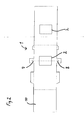
- Fig. 1 shows a plan view of a preferred embodiment of the card according to the invention.
- the card has a card body 1 with a recess 2.
- a rotary display 3 is arranged in the recess 2 and is rotatable by more than 180 ° relative to the card main body 1.
- the rotation of the rotary display 3 is effected by actuation of an actuating element 4 which is movable relative to the card main body 1 and which is mounted and / or guided in the embodiment shown in FIG. 1 between the front side and the back side of the card main body (the actuating element 4 is shown in dashed lines in Fig. 1).
- the reciprocating movement of the actuating element 4 takes place in the preferred embodiment of the card according to the invention shown in FIG. 1 by opening or closing a foldable cover flap 10, to which the actuating element 4 is connected.
- the reciprocating motion of the actuating element 4 is converted into a rotational movement of the rotary element 5 and thus of the rotary display 3 via the two transmission elements 6, which are guided and wound around the body of the rotary element 5.
- the actuating element 4 has an actuating element opening, which is preferably dimensioned such that it does not cover the recess 2 in every position of the actuating element 4.
- a part of the actuating element 4 protrudes through an opening 9, here designed as a slot, of the card main body 1 and is correspondingly attached to the hinged cover flap 10.
- Fig. 2 shows the card body 1 of the embodiment of the inventive Shen card, as shown in Fig. 1, in the unfolded state.
- the card main body 1 which is shown in FIG. 2, has a front side and a rear side, which are connected to one another along a folding card, wherein the card main body 1 in the folded state forms at least the opening, here as a slot (see FIG. 1), between the front side and the rear side, and wherein the front side has a front side opening and the rear side has a rear side opening which in the folded state congruently overlap one another and form the recess 2.
- the card body 1 furthermore has bearings 7, 8, which are designed here as bearing lugs and support the rotary element (indicated by a dash in FIG. 2). Furthermore, adhesive tabs are provided, by means of which the front side and the rear side of the card main body can be glued together permanently.
- the card main body 1 also has a portion which can serve as a hinged cover flap 10.
- FIG. 3 shows a top view of the actuating element 4 in a sectional plan view, as can be used in the preferred embodiment of the card according to the invention as shown in FIG.
- the transmission elements 6 can be firmly connected to the actuating element 4.
- the actuator opening of the actuating element 4 which is dimensioned so that it does not obscure the recess 2 of the card body 1 in any position of the actuating element 4.
- the card main body 1, the rotary display 3 and the actuator 4 may preferably be made of paper, cardboard, cardboard or a suitable plastic material.
- the rotary member 5 is preferably made of wood, metal or a plastic material.
- the transmission elements 6 are preferably each formed by threads or bands, which preferably consist of natural fiber and / or plastic material.
Landscapes
- Physics & Mathematics (AREA)
- General Physics & Mathematics (AREA)
- Engineering & Computer Science (AREA)
- Theoretical Computer Science (AREA)
- Credit Cards Or The Like (AREA)
- Displays For Variable Information Using Movable Means (AREA)
- Devices For Indicating Variable Information By Combining Individual Elements (AREA)
- Instructional Devices (AREA)
Abstract
Description
- Die Erfindung betrifft eine Karte mit einem Display, nämlich einem Drehdisplay, welche beispielsweise als Werbekarte Verwendung finden kann.
- Das deutsche Gebrauchsmuster
DE 1 871 062 U beschreibt beispielsweise eine aufklappbare Doppelkarte, welche als Werbe- oder Glückwunschkarte Verwendung finden kann, bei welcher in einer Aussparung im Randbereich der Karte eine Figur vorgesehen ist, die mittels eines an beiden Enden gespannt an der Karte befestigten, aus mehreren Einzelfäden verdrillten Faden drehbar befestigt ist. - Die vorliegende Erfindung sieht nun eine Karte mit Display, nämlich mit einem Drehdisplay, vor, welche eine reproduzierbare Drehbewegung dieses Drehdisplays relativ zu einem Kartenkörper erlaubt. Dies erhöht den Aufmerksamkeitswert einer solchen Karte.
- Die Aufgabe der vorliegenden Erfindung wird gelöst durch eine erfindungsgemäße Karte mit den Merkmalen gemäß Anspruch 1.
- Vorteilhafte Ausführungsformen sind in den Unteransprüchen beschrieben.
- Die Karte mit Display weist erfindungsgemäß einen Grundkörper mit einer Aussparung, ein Drehdisplay, welches in der Aussparung angeordnet ist und um mehr als 180°, bevorzugt um mehr als 360°, (auch weniger oder deutlich mehr) relativ zum Kartengrundkörper, d.h. zu der durch den Kartengrundkörper definierten Ebene, drehbar ist, ein Betätigungselement, welches relativ zu dem Kartengrundkörper bewegbar ist, insbesondere in einer gradlinigen ebenen Bewegung, insbesondere in der Ebene, welche durch den Kartengrundkörper definiert ist, ein Drehelement, welches drehbar relativ zu dem Kartengrundkörper gelagert ist und welches das Drehdisplay trägt, und zumindest ein Übertragungselement auf, welches die Bewegung des Betätigungselements auf das Drehelement überträgt, d.h. welches die ebene Bewegung des Betätigungselements auf eine Drehbewegung des Drehelements überträgt.
- Gemäß einer bevorzugten Ausführungsform weist der Kartengrundkörper ein Lager, z.B. in Form von Lagerlaschen, auf, welche das Drehelement lagern. Dadurch wird ermöglicht, dass sich das Drehelement in einer Ebene, welche bevorzugt durch den Kartengrundkörper definiert ist, drehen kann.
- Des Weiteren ist eine Ausführungsform der vorliegenden Erfindung bevorzugt, bei welcher der Kartengrundkörper eine Vorderseite und Rückseite aufweist, welche entlang einer Faltkante miteinander verbunden sind, wobei der Kartengrundkörper im gefalteten Zustand zumindest eine Öffnung zwischen der Vorderseite und der Rückseite aufweist und wobei die Vorderseite eine Vorderseiten-Öffnung aufweist und die Rückseite eine Rückseiten-Offnung aufweist, welche im gefalteten Zustand deckungsgleich übereinander liegen und die Aussparung bilden. Auf diese Weise ist eine besonders einfache Gestaltung des Kartengrundkörpers möglich, da ein solcher Kartengrundkörper als einfaches Schnittmuster- bzw. Stanzteil ausgeführt werden kann, welches nur noch durch Umklappen in die entsprechende Endform gebracht werden muss, wobei zusätzlich Laschen vorgesehen sein können, an welchen die Vorderseite und die Rückseite des Kartengrundkörpers z.B. miteinander verklebt sein können.
- Um eine einfache Anwendung der erfindungsgemäßen Karte mit Drehdisplay zu ermöglichen, ist gemäß einer bevorzugten Ausführungsform der Erfindung das Betätigungselement in dem Kartengrundkörper geführt, wobei es durch Hinein- und Herausschieben in/aus oder durch Hin- und Herschieben relativ zu der Öffnung bewegbar ist.
- Gemäß einer weiteren bevorzugten Ausführungsform der Erfindung ist das Betätigungselement in dem Kartengrundkörper geführt und es ragt zumindest teilweise aus der Öffnung hervor.
- Bevorzugt weist das Betätigungselement eine Betätigungselement-Öffnung auf, welche so dimensioniert ist, dass sie in jeder Stellung des Betätigungselements die Aussparung in dem Kartengrundkörper nicht verdeckt.
- Um die Bewegung des Betätigungselements auf das Drehelement möglich einfach und effektiv zu ermöglichen, ist gemäß einer bevorzugten Ausführungsform das zumindest eine Übertragungselement an dem Betätigungselement fest verbunden und es besteht zwischen dem zumindest einen Übertragungselement und Drehelement eine reibschlüssige Verbindung. Dies erlaubt ein einfaches Hin- und Herbewegen und eine damit verbundene sichere Übertragung der entsprechenden Bewegung in eine Drehbewegung des Drehelements und damit auch des mit dem Drehelement verbundenen Drehdisplays.
- Es kann auch eine Ausführungsform bevorzugt sein, bei welcher das zumindest eine Übertragungselement an dem Betätigungselement und an dem Drehelement fest verbunden ist.
- Bevorzugt weist der Kartengrundkörper zusätzlich eine klappbare Abdecklasche auf, welche mit dem Betätigungselement verbunden ist, wobei die Verbindung so ausgebildet ist, dass die Klappbewegung der Abdecklasche das Betätigungselement bewegt.
- Es kann auch möglich sein, die entsprechende Kartengestaltung beispielsweise in eine Heftbindung oder eine Buchbindung zu integrieren, wobei die Funktion der Abdecklasche z.B. auch durch eine Einbandseite oder eine vorhergehende oder nachfolgende Seite erfüllt werden kann. Die erfindungsgemäße Karte kann dabei auch als Einbandseite in die Heft- oder Buchbindung integriert sein.
- Der Kartengrundkörper, das Drehdisplay und das Betätigungselement können bevorzugt aus Papier, Pappe, Karton oder Kunststoffmaterial bestehen. Das Drehelement kann bevorzugt aus Holz, Metall oder Kunststoffmaterial bestehen und in seinem Querschnitt bevorzugt rund sein, es ist jedoch auch möglich, bei entsprechend angepasster Lagerung einen mehreckigen, z.B. rechteckigen, sechseckigen, achteckigen oder auch einen dreieckigen, Querschnitt des Drehelements zu wählen.
- Das Übertragungselement ist bevorzugt ein Faden oder ein Band, welcher bevorzugt aus Naturfaser- oder Kunststoffmaterial besteht. Der Faden oder das Band kann dabei entweder möglichst nicht elastisch oder dehnbar sein, da dadurch die Übertragung der Hin- und Herbewegung des Betätigungselements auf das Drehelement eher verschlechtert werden würde, oder der Faden oder das Band kann durch definierte Wahl des Verlaufs der Elastizität in Abhängigkeit von der Bewegung die Bewegung des Betätigungselements "verzögert" oder nicht synchron, d.h. nicht proportional, zur Bewegung des Betätigungselements, auf das Drehelement übertragen. Das Übertragungselement kann bevorzugt auch integral mit dem Betätigungselement ausgebildet sein.
- Generell erfolgt die Übertragung der Hin- und Herbewegung des Betätigungselements in eine Drehbewegung des Drehelementes und damit in eine Drehbewegung des daran angebrachten Drehdisplays über das Übertragungselement, welches ein Drehmoment auf das Drehelement überträgt.
- Das Ausmaß der Drehung des Drehelements und somit des Drehdisplays ist bestimmt durch die Bewegung des Betätigungselements und sie kann entweder proportional zu der Bewegung des Betätigungselements sein, oder "verzögert" oder nicht synchron (siehe oben).
- Die Übertragung der Bewegung des Betätigungselements in die Bewegung des Drehelementes kann erfolgen durch die Wahl von sich entsprechend ändernden, z.B. abschnittsweise sich ändernden, Reibungsparametern zwischen Drehelement und Übertragungselement und/oder zwischen Betätigungselement und Übertragungselement, wobei das Ausmaß der Drehung des Drehelements und somit des Drehdisplays dabei bestimmt ist durch die Bewegung des Betätigungselements und wobei das Ausmaß der Drehung dabei entweder proportional zu der Bewegung des Betätigungselements sein kann, oder "verzögert" oder nicht synchron.
- Die Erfindung wird im Folgenden beschrieben anhand der Ausfiihrungsform, welche beispielhaft in den beigefügten Zeichnungen dargestellt ist, in welchen:
- Fig. 1
- eine Draufsicht auf eine erfindungsgemäße Karte mit Drehdisplay ist, welche gestrichelt das Innenleben der Karte zeigt;
- Fig. 2
- den Kartengrundkörper der in Fig. 1 gezeigten Ausführungsform in einem aufgeklappten Zustand zeigt; und
- Fig. 3
- das Betätigungselement zusammen mit dem Übertragungselement gemäß der in Fig. 1 gezeigten Ausführungsform zeigt.
- Fig. 1 zeigt in einer Draufsicht eine bevorzugte Ausführungsform der erfindungsgemäßen Karte. Die Karte weist einen Kartenkörper 1 mit einer Aussparung 2 auf. Ein Drehdisplay 3 ist in der Aussparung 2 angeordnet und es ist um mehr als 180° relativ zu dem Kartengrundkörper 1 drehbar. Die Drehung des Drehdisplays 3 wird bewirkt durch Betätigung eines Betätigungselements 4, welches relativ zu dem Kartengrundkörper 1 bewegbar ist und welches sich in der in Fig. 1 gezeigten Ausführungsform zwischen der Vorderseite und der Rückseite des Kartengrundkörpers gelagert und/oder geführt befindet (das Betätigungselement 4 ist gestrichelt in Fig. 1 wiedergegeben). Durch die relative Bewegung des Betätigungselements 4 im Kartenkörper 1 wird über bevorzugt zwei Übertragungselemente 6, welche an dem Betätigungselement 4 in entsprechenden Öffnungen befestigt sind und aus einem Faden bestehen, eine Drehbewegung auf ein Drehelement 5 übertragen, welches in Lagern 7, 8, welche hier als Lagerlaschen ausgebildet sind, des Kartengrundkörpers 1 gelagert ist und welches das Drehdisplay 3 trägt. Generell sind die Bewegungsabläufe durch Pfeile in Fig. 1 angedeutet.
- Die Hin- und Herbewegung des Betätigungselements 4 erfolgt in der in Fig. 1 gezeigten bevorzugten Ausführungsform der erfindungsgemäßen Karte durch Auf- bzw. Zuklappen einer klappbaren Abdecklasche 10, an welcher das Betätigungselement 4 verbunden ist. Die Hin- und Herbewegung des Betätigungselements 4 wird über die beiden Übertragungselemente 6, welche um den Körper des Drehelements 5 geführt und gewickelt sind, in eine Drehbewegung des Drehelements 5 und damit des Drehdisplays 3 umgewandelt. Zwischen dem Übertragungselement 6 und dem Drehelement 5 besteht dabei eine bevorzugt reibflüssige Verbindung. Das Betätigungselement 4 weist eine Betätigungselement-Öffnung auf, welche bevorzugt so dimensioniert ist, dass sie in jeder Stellung des Betätigungselements 4 die Aussparung 2 nicht verdeckt. Ein Teil des Betätigungselements 4 ragt durch eine Öffnung 9, hier als Schlitz ausgebildet, des Kartengrundkörpers 1 hervor und ist entsprechend an der klappbaren Abdecklasche 10 angebracht.
- Fig. 2 zeigt den Kartengrundkörper 1 der Ausführungsform der erfindungsgemä-ßen Karte, wie sie in Fig. 1 gezeigt ist, in aufgeklapptem Zustand.
- Der Kartengrundkörper 1, welcher in Fig. 2 gezeigt ist, weist eine Vorderseite und eine Rückseite auf, welche entlang einer Faltkarte miteinander verbunden sind, wobei der Kartengrundkörper 1 im gefalteten Zustand zumindest die Öffnung, hier als Schlitz ausgebildet (siehe Fig. 1), zwischen der Vorderseite und der Rückseite aufweist und wobei die Vorderseite eine Vorderseiten-Öffnung aufweist und die Rückseite eine Rückseiten-Öffnung aufweist, welche im gefalteten Zustand deckungsgleich übereinander liegen und die Aussparung 2 bilden. Der Kartengrundkörper 1 weist femer Lager 7, 8 auf, welche hier als Lagerlaschen ausgebildet sind und das Drehelement (in Fig. 2 durch einen Strich angedeutet) lagern. Ferner sind Klebelaschen vorgesehen, mittels welchen die Vorderseite und die Rückseite des Kartengrundkörpers dauerhaft miteinander verklebt werden können. Der Kartengrundkörper 1 weist außerdem einen Abschnitt auf, welcher als klappbare Abdecklasche 10 dienen kann.
- Figur 3 zeigt in einer Draufsicht schnittmusterartig das Betätigungselement 4, wie es in der bevorzugten Ausführungsform der erfindungsgemäßen Karte gemäß Fig. 1 einsetzbar ist.
- In entsprechenden Öffnungen bzw. Kerben des Betätigungselements 4 können die Übertragungselemente 6 fest mit dem Betätigungselement 4 verbunden sein. Au-ßerdem zu sehen ist in Fig. 3 auch die Betätigungselement-Öffnung des Betätigungselements 4, welches so dimensioniert ist, dass sie in jeder Stellung des Betätigungselements 4 die Aussparung 2 des Kartengrundkörpers 1 nicht verdeckt.
- Allgemein können der Kartengrundkörper 1, das Drehdisplay 3 und das Betätigungselement 4 bevorzugt aus Papier, Pappe, Karton oder einem geeigneten Kunststoffmaterial bestehen. Das Drehelement 5 besteht bevorzugt aus Holz, Metall oder einem Kunststoffmaterial. Die Übertragungselemente 6 sind bevorzugt jeweils durch Fäden oder Bänder gebildet, welche bevorzugt aus Naturfaser und/oder Kunststoffmaterial bestehen.
Claims (14)
- Karte mit Display, dadurch gekennzeichnet, dass die Karte aufweist:einen Kartengrundkörper (1) mit einer Aussparung (2),ein Drehdisplay (3), welches in der Aussparung (2) angeordnet ist undum mehr als 180 Grad relativ zum Kartengrundkörper (1) drehbar ist, ein Betätigungselement (4), welches relativ zu dem Kartengrundkörper (1) bewegbar ist,ein Drehelement (5), welches drehbar relativ zu dem Kartengrundkörper (1) gelagert ist und welches das Drehdisplay (3) trägt,zumindest ein Übertragungselement (6), welches die Bewegung des Betätigungselements (4) auf das Drehelement (5) überträgt.
- Karte gemäß Anspruch 1, dadurch gekennzeichnet, dass das Drehdisplay (3) um mehr als 360 Grad relativ zum Kartengrundkörper (1) drehbar ist.
- Karte gemäß Anspruch 1 oder 2, dadurch gekennzeichnet, dass der Kartengrundkörper (1) Lager (7, 8) aufweist, welche das Drehelement (5) lagern.
- Karte gemäß zumindest einem der Ansprüche 1 bis 3, dadurch gekennzeichnet, dass der Kartengrundkörper (1) eine Vorderseite und eine Rückseite aufweist, welche entlang einer Faltkante miteinander verbunden sind, wobei der Kartengrundkörper (1) im gefalteten Zustand zumindest einen Öffnung (9) zwischen der Vorderseite und der Rückseite aufweist und wobei die Vorderseite eine Vorderseiten-Öffnung aufweist und die Rückseite eine Rückseiten-Offnung aufweist, welche im gefalteten Zustand deckungsgleich übereinander liegen und die Aussparung (2) bilden.
- Karte gemäß Anspruch 4, dadurch gekennzeichnet, dass das Betätigungselement (4) in dem Kartengrundkörper (1) geführt ist und durch Hinein- und Herausschieben in/aus oder durch Hin- und Herschieben relativ zu der Öffnung (9) bewegbar ist.
- Karte gemäß Anspruch 4 oder 5, dadurch gekennzeichnet, dass das Betätigungselement (4) in dem Kartengrundkörper (1) geführt ist und zumindest teilweise aus der Öffnung (9) hervorragt.
- Karte gemäß zumindest einem der Ansprüche 1 bis 6, dadurch gekennzeichnet, dass das Betätigungselement (4) eine Betätigungselement-Öffnung aufweist, welche so dimensioniert ist, dass sie in jeder Stellung des Betätigungselements (4) die Aussparung (2) nicht verdeckt
- Karte gemäß zumindest einem der Ansprüche 1 bis 7, dadurch gekennzeichnet, dass das zumindest eine Übertragungselement (6) an dem Betätigungselement (4) fest verbunden ist und mit dem Drehelement (5) eine reibschlüssige Verbindung bildet.
- Karte gemäß zumindest einem der Ansprüche 1 bis 7, dadurch gekennzeichnet, dass das zumindest eine Übertragungselement (6) an dem Betätigungselement (4) und an dem Drehelement (5) fest verbunden ist.
- Karte gemäß zumindest einem der Ansprüche 1 bis 9, dadurch gekennzeichnet, dass der Kartengrundkörper (1) eine klappbare Abdecklasche (10) aufweist, welche mit dem Betätigungselement (4) verbunden ist, wobei die Verbindung so ausgebildet ist, dass die Klappbewegung der Abdecklasche (10) das Betätigungselement (4) bewegt.
- Karte gemäß zumindest einem der Ansprüche 1 bis 10, dadurch gekennzeichnet, dass der Kartengrundkörper (1), das Drehdisplay (3) und das Betätigungselement (4) aus Papier, Pappe, Karton oder Kunststoffmaterial bestehen.
- Karte gemäß zumindest einem der Ansprüche 1 bis 11, dadurch gekennzeichnet, dass das Drehelement (5) aus Kunststoffmaterial, Holz oder Metall besteht.
- Karte gemäß zumindest einem der Ansprüche 1 bis 12, dadurch gekennzeichnet, dass das zumindest eine Übertragungselement (6) ein Faden oder ein Band ist, welcher bevorzugt aus Naturfaser- oder Kunststoffmaterial besteht.
- Karte gemäß zumindest einem der Ansprüche 1 bis 12, dadurch gekennzeichnet, dass das zumindest eine Übertragungselement (6) integral mit dem Betätigungselement (4) ausgebildet ist.
Applications Claiming Priority (1)
| Application Number | Priority Date | Filing Date | Title |
|---|---|---|---|
| DE102005020633A DE102005020633A1 (de) | 2005-05-03 | 2005-05-03 | Karte mit Drehdisplay |
Publications (3)
| Publication Number | Publication Date |
|---|---|
| EP1720145A2 true EP1720145A2 (de) | 2006-11-08 |
| EP1720145A3 EP1720145A3 (de) | 2008-06-25 |
| EP1720145B1 EP1720145B1 (de) | 2011-05-11 |
Family
ID=36847708
Family Applications (1)
| Application Number | Title | Priority Date | Filing Date |
|---|---|---|---|
| EP06005824A Expired - Lifetime EP1720145B1 (de) | 2005-05-03 | 2006-03-22 | Karte mit Drehdisplay |
Country Status (3)
| Country | Link |
|---|---|
| EP (1) | EP1720145B1 (de) |
| AT (1) | ATE509339T1 (de) |
| DE (1) | DE102005020633A1 (de) |
Cited By (1)
| Publication number | Priority date | Publication date | Assignee | Title |
|---|---|---|---|---|
| EP3115224A1 (de) * | 2015-06-25 | 2017-01-11 | Elco AG | Schreibmappe |
Citations (2)
| Publication number | Priority date | Publication date | Assignee | Title |
|---|---|---|---|---|
| US3061971A (en) | 1959-11-09 | 1962-11-06 | Upjohn Co | Rotating display |
| DE1871062U (de) | 1962-12-28 | 1963-04-25 | Graphische Kunstanstalt Schult | Aufklappbare doppelkarte. |
Family Cites Families (2)
| Publication number | Priority date | Publication date | Assignee | Title |
|---|---|---|---|---|
| US2943416A (en) * | 1958-03-19 | 1960-07-05 | Barker Alvin | Greeting card or folder |
| DE29813155U1 (de) * | 1998-07-23 | 1998-10-15 | Refeka Werbemittel GmbH, 85551 Kirchheim | Schieberkarte |
-
2005
- 2005-05-03 DE DE102005020633A patent/DE102005020633A1/de not_active Ceased
-
2006
- 2006-03-22 EP EP06005824A patent/EP1720145B1/de not_active Expired - Lifetime
- 2006-03-22 AT AT06005824T patent/ATE509339T1/de active
Patent Citations (2)
| Publication number | Priority date | Publication date | Assignee | Title |
|---|---|---|---|---|
| US3061971A (en) | 1959-11-09 | 1962-11-06 | Upjohn Co | Rotating display |
| DE1871062U (de) | 1962-12-28 | 1963-04-25 | Graphische Kunstanstalt Schult | Aufklappbare doppelkarte. |
Cited By (1)
| Publication number | Priority date | Publication date | Assignee | Title |
|---|---|---|---|---|
| EP3115224A1 (de) * | 2015-06-25 | 2017-01-11 | Elco AG | Schreibmappe |
Also Published As
| Publication number | Publication date |
|---|---|
| DE102005020633A1 (de) | 2006-11-16 |
| EP1720145B1 (de) | 2011-05-11 |
| EP1720145A3 (de) | 2008-06-25 |
| ATE509339T1 (de) | 2011-05-15 |
Similar Documents
| Publication | Publication Date | Title |
|---|---|---|
| DE202010009919U1 (de) | Scharnier mit Torsions-Spiral-Feder, deren Spannung einstellbar ist | |
| DE2255253B1 (de) | Klemmvorrichtung zum lösbaren Zusammenhalten einer Mehrzahl aufeinander geschichteter Büropapiere | |
| DE112016000844T5 (de) | Drehgelenkvorrichtung und Verfahren zum Erzeugen eines asymmetrischen Reibungsdrehmoments | |
| WO2006026800A9 (de) | Blattanhebevorrichtung mit spitzwinklig angeordneter schwenkachse des motors | |
| EP1720145B1 (de) | Karte mit Drehdisplay | |
| DE3006125C2 (de) | Skibremse | |
| DE1179911B (de) | Aufreilhvorrichtung fuer Briefordner | |
| DE202005007094U1 (de) | Karte mit Drehdisplay | |
| DE202008004862U1 (de) | Buch | |
| DE3208314C2 (de) | ||
| DE102008014493A1 (de) | Reversibel formveränderbare Pop-Up Konstruktion per Rotationsmechanismus | |
| DE102007010921A1 (de) | Klappgehäuse | |
| EP2380457A1 (de) | Notenpultmappe | |
| DE102007033687A1 (de) | Buch mit einer Aufstellvorrichtung | |
| AT144166B (de) | Lesezeichen. | |
| DE3040280C2 (de) | Halterung mit einen Blattstapel | |
| DE268842C (de) | ||
| DE1123290B (de) | Notizkalender | |
| EP1581396B1 (de) | Vorrichtung zum umblättern von seiten eines buches | |
| DE3428034C1 (de) | Mappe, insbesondere zum Aufbewahren von Manuskripten oder dergleichen | |
| DE569900C (de) | Maschine zum Heften von Papierblaettern | |
| DE915449C (de) | Halteeinrichtung fuer gefaltete Blaetter | |
| AT12723U1 (de) | Abdeckvorrichtung für trinkgefässe | |
| DE20218012U1 (de) | Visitenkarte | |
| DE202010016762U1 (de) | Geschenktasche |
Legal Events
| Date | Code | Title | Description |
|---|---|---|---|
| PUAI | Public reference made under article 153(3) epc to a published international application that has entered the european phase |
Free format text: ORIGINAL CODE: 0009012 |
|
| AK | Designated contracting states |
Kind code of ref document: A2 Designated state(s): AT BE BG CH CY CZ DE DK EE ES FI FR GB GR HU IE IS IT LI LT LU LV MC NL PL PT RO SE SI SK TR |
|
| AX | Request for extension of the european patent |
Extension state: AL BA HR MK YU |
|
| PUAL | Search report despatched |
Free format text: ORIGINAL CODE: 0009013 |
|
| AK | Designated contracting states |
Kind code of ref document: A3 Designated state(s): AT BE BG CH CY CZ DE DK EE ES FI FR GB GR HU IE IS IT LI LT LU LV MC NL PL PT RO SE SI SK TR |
|
| AX | Request for extension of the european patent |
Extension state: AL BA HR MK YU |
|
| RIC1 | Information provided on ipc code assigned before grant |
Ipc: B42D 15/04 20060101ALI20080522BHEP Ipc: G09F 1/10 20060101ALI20080522BHEP Ipc: G09F 11/06 20060101ALI20080522BHEP Ipc: G09F 1/06 20060101AFI20060830BHEP Ipc: G09F 1/12 20060101ALI20080522BHEP |
|
| 17P | Request for examination filed |
Effective date: 20081208 |
|
| AKX | Designation fees paid |
Designated state(s): AT BE BG CH CY CZ DE DK EE ES FI FR GB GR HU IE IS IT LI LT LU LV MC NL PL PT RO SE SI SK TR |
|
| 17Q | First examination report despatched |
Effective date: 20090218 |
|
| GRAP | Despatch of communication of intention to grant a patent |
Free format text: ORIGINAL CODE: EPIDOSNIGR1 |
|
| RIC1 | Information provided on ipc code assigned before grant |
Ipc: G09F 11/06 20060101ALI20101115BHEP Ipc: G09F 1/06 20060101AFI20101115BHEP Ipc: B42D 15/02 20060101ALI20101115BHEP Ipc: G09F 1/12 20060101ALI20101115BHEP Ipc: G09F 1/10 20060101ALI20101115BHEP |
|
| GRAS | Grant fee paid |
Free format text: ORIGINAL CODE: EPIDOSNIGR3 |
|
| GRAA | (expected) grant |
Free format text: ORIGINAL CODE: 0009210 |
|
| AK | Designated contracting states |
Kind code of ref document: B1 Designated state(s): AT BE BG CH CY CZ DE DK EE ES FI FR GB GR HU IE IS IT LI LT LU LV MC NL PL PT RO SE SI SK TR |
|
| REG | Reference to a national code |
Ref country code: GB Ref legal event code: FG4D Free format text: NOT ENGLISH |
|
| REG | Reference to a national code |
Ref country code: CH Ref legal event code: EP |
|
| REG | Reference to a national code |
Ref country code: IE Ref legal event code: FG4D |
|
| REG | Reference to a national code |
Ref country code: DE Ref legal event code: R096 Ref document number: 502006009461 Country of ref document: DE Effective date: 20110622 |
|
| REG | Reference to a national code |
Ref country code: CH Ref legal event code: NV Representative=s name: HEPP WENGER RYFFEL AG |
|
| REG | Reference to a national code |
Ref country code: NL Ref legal event code: T3 |
|
| PG25 | Lapsed in a contracting state [announced via postgrant information from national office to epo] |
Ref country code: SE Free format text: LAPSE BECAUSE OF FAILURE TO SUBMIT A TRANSLATION OF THE DESCRIPTION OR TO PAY THE FEE WITHIN THE PRESCRIBED TIME-LIMIT Effective date: 20110511 Ref country code: PT Free format text: LAPSE BECAUSE OF FAILURE TO SUBMIT A TRANSLATION OF THE DESCRIPTION OR TO PAY THE FEE WITHIN THE PRESCRIBED TIME-LIMIT Effective date: 20110912 Ref country code: LT Free format text: LAPSE BECAUSE OF FAILURE TO SUBMIT A TRANSLATION OF THE DESCRIPTION OR TO PAY THE FEE WITHIN THE PRESCRIBED TIME-LIMIT Effective date: 20110511 |
|
| PG25 | Lapsed in a contracting state [announced via postgrant information from national office to epo] |
Ref country code: ES Free format text: LAPSE BECAUSE OF FAILURE TO SUBMIT A TRANSLATION OF THE DESCRIPTION OR TO PAY THE FEE WITHIN THE PRESCRIBED TIME-LIMIT Effective date: 20110822 Ref country code: FI Free format text: LAPSE BECAUSE OF FAILURE TO SUBMIT A TRANSLATION OF THE DESCRIPTION OR TO PAY THE FEE WITHIN THE PRESCRIBED TIME-LIMIT Effective date: 20110511 Ref country code: CY Free format text: LAPSE BECAUSE OF FAILURE TO SUBMIT A TRANSLATION OF THE DESCRIPTION OR TO PAY THE FEE WITHIN THE PRESCRIBED TIME-LIMIT Effective date: 20110511 Ref country code: LV Free format text: LAPSE BECAUSE OF FAILURE TO SUBMIT A TRANSLATION OF THE DESCRIPTION OR TO PAY THE FEE WITHIN THE PRESCRIBED TIME-LIMIT Effective date: 20110511 Ref country code: GR Free format text: LAPSE BECAUSE OF FAILURE TO SUBMIT A TRANSLATION OF THE DESCRIPTION OR TO PAY THE FEE WITHIN THE PRESCRIBED TIME-LIMIT Effective date: 20110812 Ref country code: IS Free format text: LAPSE BECAUSE OF FAILURE TO SUBMIT A TRANSLATION OF THE DESCRIPTION OR TO PAY THE FEE WITHIN THE PRESCRIBED TIME-LIMIT Effective date: 20110911 Ref country code: SI Free format text: LAPSE BECAUSE OF FAILURE TO SUBMIT A TRANSLATION OF THE DESCRIPTION OR TO PAY THE FEE WITHIN THE PRESCRIBED TIME-LIMIT Effective date: 20110511 |
|
| REG | Reference to a national code |
Ref country code: IE Ref legal event code: FD4D |
|
| PG25 | Lapsed in a contracting state [announced via postgrant information from national office to epo] |
Ref country code: IE Free format text: LAPSE BECAUSE OF FAILURE TO SUBMIT A TRANSLATION OF THE DESCRIPTION OR TO PAY THE FEE WITHIN THE PRESCRIBED TIME-LIMIT Effective date: 20110511 Ref country code: EE Free format text: LAPSE BECAUSE OF FAILURE TO SUBMIT A TRANSLATION OF THE DESCRIPTION OR TO PAY THE FEE WITHIN THE PRESCRIBED TIME-LIMIT Effective date: 20110511 |
|
| PG25 | Lapsed in a contracting state [announced via postgrant information from national office to epo] |
Ref country code: SK Free format text: LAPSE BECAUSE OF FAILURE TO SUBMIT A TRANSLATION OF THE DESCRIPTION OR TO PAY THE FEE WITHIN THE PRESCRIBED TIME-LIMIT Effective date: 20110511 Ref country code: PL Free format text: LAPSE BECAUSE OF FAILURE TO SUBMIT A TRANSLATION OF THE DESCRIPTION OR TO PAY THE FEE WITHIN THE PRESCRIBED TIME-LIMIT Effective date: 20110511 Ref country code: RO Free format text: LAPSE BECAUSE OF FAILURE TO SUBMIT A TRANSLATION OF THE DESCRIPTION OR TO PAY THE FEE WITHIN THE PRESCRIBED TIME-LIMIT Effective date: 20110511 Ref country code: DK Free format text: LAPSE BECAUSE OF FAILURE TO SUBMIT A TRANSLATION OF THE DESCRIPTION OR TO PAY THE FEE WITHIN THE PRESCRIBED TIME-LIMIT Effective date: 20110511 |
|
| PLBE | No opposition filed within time limit |
Free format text: ORIGINAL CODE: 0009261 |
|
| STAA | Information on the status of an ep patent application or granted ep patent |
Free format text: STATUS: NO OPPOSITION FILED WITHIN TIME LIMIT |
|
| 26N | No opposition filed |
Effective date: 20120214 |
|
| PG25 | Lapsed in a contracting state [announced via postgrant information from national office to epo] |
Ref country code: IT Free format text: LAPSE BECAUSE OF FAILURE TO SUBMIT A TRANSLATION OF THE DESCRIPTION OR TO PAY THE FEE WITHIN THE PRESCRIBED TIME-LIMIT Effective date: 20110511 |
|
| REG | Reference to a national code |
Ref country code: DE Ref legal event code: R097 Ref document number: 502006009461 Country of ref document: DE Effective date: 20120214 |
|
| BERE | Be: lapsed |
Owner name: REFEKA WERBEMITTEL G.M.B.H. Effective date: 20120331 |
|
| PG25 | Lapsed in a contracting state [announced via postgrant information from national office to epo] |
Ref country code: MC Free format text: LAPSE BECAUSE OF NON-PAYMENT OF DUE FEES Effective date: 20120331 |
|
| GBPC | Gb: european patent ceased through non-payment of renewal fee |
Effective date: 20120322 |
|
| PG25 | Lapsed in a contracting state [announced via postgrant information from national office to epo] |
Ref country code: GB Free format text: LAPSE BECAUSE OF NON-PAYMENT OF DUE FEES Effective date: 20120322 Ref country code: BE Free format text: LAPSE BECAUSE OF NON-PAYMENT OF DUE FEES Effective date: 20120331 |
|
| REG | Reference to a national code |
Ref country code: AT Ref legal event code: MM01 Ref document number: 509339 Country of ref document: AT Kind code of ref document: T Effective date: 20120322 |
|
| PG25 | Lapsed in a contracting state [announced via postgrant information from national office to epo] |
Ref country code: BG Free format text: LAPSE BECAUSE OF FAILURE TO SUBMIT A TRANSLATION OF THE DESCRIPTION OR TO PAY THE FEE WITHIN THE PRESCRIBED TIME-LIMIT Effective date: 20110811 |
|
| PG25 | Lapsed in a contracting state [announced via postgrant information from national office to epo] |
Ref country code: AT Free format text: LAPSE BECAUSE OF NON-PAYMENT OF DUE FEES Effective date: 20120322 |
|
| PG25 | Lapsed in a contracting state [announced via postgrant information from national office to epo] |
Ref country code: TR Free format text: LAPSE BECAUSE OF FAILURE TO SUBMIT A TRANSLATION OF THE DESCRIPTION OR TO PAY THE FEE WITHIN THE PRESCRIBED TIME-LIMIT Effective date: 20110511 |
|
| PG25 | Lapsed in a contracting state [announced via postgrant information from national office to epo] |
Ref country code: LU Free format text: LAPSE BECAUSE OF NON-PAYMENT OF DUE FEES Effective date: 20120322 |
|
| PG25 | Lapsed in a contracting state [announced via postgrant information from national office to epo] |
Ref country code: HU Free format text: LAPSE BECAUSE OF FAILURE TO SUBMIT A TRANSLATION OF THE DESCRIPTION OR TO PAY THE FEE WITHIN THE PRESCRIBED TIME-LIMIT Effective date: 20060322 |
|
| REG | Reference to a national code |
Ref country code: FR Ref legal event code: PLFP Year of fee payment: 11 |
|
| PGFP | Annual fee paid to national office [announced via postgrant information from national office to epo] |
Ref country code: CZ Payment date: 20160315 Year of fee payment: 11 Ref country code: NL Payment date: 20160322 Year of fee payment: 11 |
|
| PGFP | Annual fee paid to national office [announced via postgrant information from national office to epo] |
Ref country code: FR Payment date: 20160322 Year of fee payment: 11 |
|
| PG25 | Lapsed in a contracting state [announced via postgrant information from national office to epo] |
Ref country code: CZ Free format text: LAPSE BECAUSE OF NON-PAYMENT OF DUE FEES Effective date: 20170322 |
|
| REG | Reference to a national code |
Ref country code: NL Ref legal event code: MM Effective date: 20170401 |
|
| REG | Reference to a national code |
Ref country code: FR Ref legal event code: ST Effective date: 20171130 |
|
| PG25 | Lapsed in a contracting state [announced via postgrant information from national office to epo] |
Ref country code: NL Free format text: LAPSE BECAUSE OF NON-PAYMENT OF DUE FEES Effective date: 20170401 Ref country code: FR Free format text: LAPSE BECAUSE OF NON-PAYMENT OF DUE FEES Effective date: 20170331 |
|
| PGFP | Annual fee paid to national office [announced via postgrant information from national office to epo] |
Ref country code: CH Payment date: 20180326 Year of fee payment: 13 |
|
| PGFP | Annual fee paid to national office [announced via postgrant information from national office to epo] |
Ref country code: DE Payment date: 20190328 Year of fee payment: 14 |
|
| REG | Reference to a national code |
Ref country code: CH Ref legal event code: PL |
|
| PG25 | Lapsed in a contracting state [announced via postgrant information from national office to epo] |
Ref country code: LI Free format text: LAPSE BECAUSE OF NON-PAYMENT OF DUE FEES Effective date: 20190331 Ref country code: CH Free format text: LAPSE BECAUSE OF NON-PAYMENT OF DUE FEES Effective date: 20190331 |
|
| REG | Reference to a national code |
Ref country code: DE Ref legal event code: R119 Ref document number: 502006009461 Country of ref document: DE |
|
| PG25 | Lapsed in a contracting state [announced via postgrant information from national office to epo] |
Ref country code: DE Free format text: LAPSE BECAUSE OF NON-PAYMENT OF DUE FEES Effective date: 20201001 |