EP1720440B1 - Endoskopie-system und druckübermittelnder verbinder für dieses system - Google Patents
Endoskopie-system und druckübermittelnder verbinder für dieses system Download PDFInfo
- Publication number
- EP1720440B1 EP1720440B1 EP05706541A EP05706541A EP1720440B1 EP 1720440 B1 EP1720440 B1 EP 1720440B1 EP 05706541 A EP05706541 A EP 05706541A EP 05706541 A EP05706541 A EP 05706541A EP 1720440 B1 EP1720440 B1 EP 1720440B1
- Authority
- EP
- European Patent Office
- Prior art keywords
- channel
- path
- pressure
- irrigation
- connector
- Prior art date
- Legal status (The legal status is an assumption and is not a legal conclusion. Google has not performed a legal analysis and makes no representation as to the accuracy of the status listed.)
- Expired - Lifetime
Links
Images




Classifications
-
- A—HUMAN NECESSITIES
- A61—MEDICAL OR VETERINARY SCIENCE; HYGIENE
- A61B—DIAGNOSIS; SURGERY; IDENTIFICATION
- A61B1/00—Instruments for performing medical examinations of the interior of cavities or tubes of the body by visual or photographical inspection, e.g. endoscopes; Illuminating arrangements therefor
- A61B1/012—Instruments for performing medical examinations of the interior of cavities or tubes of the body by visual or photographical inspection, e.g. endoscopes; Illuminating arrangements therefor characterised by internal passages or accessories therefor
- A61B1/015—Control of fluid supply or evacuation
-
- A—HUMAN NECESSITIES
- A61—MEDICAL OR VETERINARY SCIENCE; HYGIENE
- A61B—DIAGNOSIS; SURGERY; IDENTIFICATION
- A61B1/00—Instruments for performing medical examinations of the interior of cavities or tubes of the body by visual or photographical inspection, e.g. endoscopes; Illuminating arrangements therefor
- A61B1/12—Instruments for performing medical examinations of the interior of cavities or tubes of the body by visual or photographical inspection, e.g. endoscopes; Illuminating arrangements therefor with cooling or rinsing arrangements
-
- A—HUMAN NECESSITIES
- A61—MEDICAL OR VETERINARY SCIENCE; HYGIENE
- A61B—DIAGNOSIS; SURGERY; IDENTIFICATION
- A61B1/00—Instruments for performing medical examinations of the interior of cavities or tubes of the body by visual or photographical inspection, e.g. endoscopes; Illuminating arrangements therefor
- A61B1/313—Instruments for performing medical examinations of the interior of cavities or tubes of the body by visual or photographical inspection, e.g. endoscopes; Illuminating arrangements therefor for introducing through surgical openings, e.g. laparoscopes
- A61B1/317—Instruments for performing medical examinations of the interior of cavities or tubes of the body by visual or photographical inspection, e.g. endoscopes; Illuminating arrangements therefor for introducing through surgical openings, e.g. laparoscopes for bones or joints, e.g. osteoscopes, arthroscopes
Definitions
- the invention relates to an endoscopy system more particularly comprising a cannula for housing an endoscope and for forming, between the cannula and the endoscope, an irrigation or suction channel and comprising a connecting ring mounted around the cannula and provided with a connection path for communicating with the irrigation or aspiration channel.
- Such an endoscopy system is described in particular by the documents US 5037386 and US 6086542 . It is used in arthroscopy of the joints and more particularly in arthroscopy of the knee.
- the endoscope is connected to a video screen to visualize the joint.
- the irrigation or aspiration channel makes it possible to create a flow of physiological water to maintain an optically clear medium in front of the endoscope and to wash the joint.
- the circulation is ensured by a pump connected to a reservoir and discharging into a tubing connected to the irrigation or suction channel via the connecting ring.
- the pressure of the physiological water in the joint is controlled by a diaphragm pressure sensor placed on the irrigation or aspiration canal tubing or on a tubing connected by the connecting ring to a channel formed in the cannula and dedicated to pressure detection, as in the case of the endoscopy systems described by the documents cited above.
- a diaphragm pressure sensor placed on the irrigation or aspiration canal tubing or on a tubing connected by the connecting ring to a channel formed in the cannula and dedicated to pressure detection, as in the case of the endoscopy systems described by the documents cited above.
- the document US 5643203 discloses an endoscopy system of the type recalled above, in which a connector is mounted on the connecting ring and comprises a communication channel with the irrigation channel and a pressure detector for detecting a pressure in the communication channel.
- the pressure of the physiological water in the joint is extrapolated by a law from the pressure detected in the communication channel.
- the extrapolation of the pressure in the articulation from the pressure detected in the communication channel of the connector eliminates a dedicated channel in the cannula at the pressure tap. It is thus possible to reduce the diameter of the cannula, with the aim of reducing the trauma when it is introduced into the joint. With respect to a tubing, the connector also eliminates the risk of a section variation of the communication channel and allows reliable detection of the pressure in this communication channel.
- the detected pressure remains subject to an artificially high pressure drop in the connection channel of the connector communication channel to the irrigation channel of the cannula. It may be a foreign body present in the connecting way of the connecting ring and partially obstructing the flow of physiological water in the irrigation channel.
- One of the aims of the invention is to overcome this disadvantage in order to confer a high degree of security to the endoscopy system.
- the subject of the invention is an endoscopy system comprising a cannula for housing an endoscope and for forming, between the cannula and the endoscope, an irrigation or aspiration channel intended for the transport of an irrigation fluid, suction respectively, a connecting ring mounted around the cannula and provided with a connecting channel to the irrigation channel, respectively suction, and a connector mounted on the connecting ring and comprising a communication channel with the connecting channel and a first pressure sensor for detecting a pressure in the communication channel, characterized in that the connecting ring is provided with a bypass channel communicating with the irrigation channel, respectively suction, and in that the connector comprises a blind path communicating with the bypass path and a second pressure sensor for detecting a pressure in this blind path.
- the bypass path of the connecting ring communicates with the blind way of the connector to allow a second detection of the pressure of the physiological clean water circulating in the irrigation channel.
- the endoscopy system according to the invention has a double security for the control of the physiological water pressure in the joint.
- the bypass channel is disposed downstream of the connection channel to the irrigation channel with respect to the transport of the fluid in irrigation, respectively upstream of the connection channel to the suction channel with respect to the transport of the suction fluid.
- an irrigation tap is provided to close or open the connection channel to the irrigation channel, upstream of the bypass, respectively a suction valve is provided to close or open the way of connection to the suction channel, downstream of the bypass.
- the invention extends to a connector intended for an endoscopy system which comprises a communication channel and a pressure detector for detecting the pressure in this communication channel, characterized in that it comprises a blind path and a second pressure sensor for detecting pressure in the blind lane.
- the connector comprises a second communication channel.
- the bypass path is disposed between the two communication channels. This arrangement makes it possible to connect to the connection ring, the communication channel for the irrigation, the blind way and the communication channel for the aspiration in a single operation, while allowing a pressure detection in the blind way and the one or the other way of communication.
- An endoscopy system includes, Figures 1 to 4 , a cannula 1 for housing an endoscope 3 and for forming, between the cannula 1 and the endoscope 3, an irrigation channel 5.
- the irrigation channel 5 is formed between the endoscope 3 and a tube 7 internal to the cannula 1 and a suction channel 9 is formed between the inner tube 7 and the cannula 1.
- the invention also applies to a cannula comprising only the irrigation channel or the suction channel.
- a connecting ring 11 is mounted around the cannula 1 to communicate with the irrigation channel 5 and the suction channel 9.
- a first connecting channel 13 communicates with the irrigation channel 5.
- a second connection channel 15 communicates with the suction channel 9.
- a connector 17 is mounted on the connecting ring 11. It comprises a first communication channel 19 for communicating with the first connection channel 13 to the irrigation channel 5 and a first pressure detector 18a and comprises a second communication channel 21 to communicate with the second connecting channel 15 to the suction channel 9.
- the two communication paths 19 and 21 of the connector 17 are arranged facing the first pressure detector 18a to detect the pressure in one or the other 19 21 of these two channels of communication.
- Unrepresented tubes are connected to the communication channels 19 and 21 of the connector 17 and connected to a pump to create a flow of clean physiological water in the irrigation channel 5 and physiological saline soiled in the suction channel 9
- the connecting ring 11 comprises valves 23 and 25 for opening or closing the connection tracks 13 and 15 as a function of the desired circulation in the irrigation channel 5 or in the suction channel 9 .
- the connector 17 is mounted on the connection ring 11 to allow the irrigation channel 5 and the suction channel 9 to communicate with the communication channels 13 and 15 of the connector without the intermediary of a tubing.
- the connecting ring 11 comprises a bypass path 27 for communicating with the connecting channel 13 to the irrigation channel 5 while the connector 17 comprises a blind way 29 for communicating with the bypass route 27 and a second pressure detector 18b for detecting a pressure in this blind way.
- the bypass path 27 of the connecting ring communicates with the blind way 29 of the connector to allow a second detection of the pressure of the physiological clean water circulating in the irrigation channel.
- the bypass route 27 is arranged, with respect to the transport of the fluid in irrigation, downstream of the connecting channel 13 to the irrigation channel 5 and the irrigation valve 23 is provided to close or open this channel of irrigation. connection 13 upstream of the bypass route 27.
- the bypass path 27 is arranged, with respect to the transport of the suction fluid, upstream of the connecting channel 15 to the suction channel 9 and the tap of suction 25 is provided to close or open this connection channel 15 downstream of the branch path 27.
- This arrangement advantageously makes it possible to detect a pressure on a track, the bypass route, undisturbed by the opening or closing, even partial, of the valve 23 of the connection channel 13 to the irrigation channel 5 or the valve 25 of the
- the pressure in the joint can be extrapolated via the bypass route even when the flow of physiological water is interrupted in the irrigation channel, respectively. suction, by closing the irrigation valve 23, respectively 25.
- the second pressure tap via the blind way makes it possible to better control the integrity of the endoscopy system according to the invention by comparing the pressures detected by the two detectors with expected values. It is thus possible to diagnose a failure of the irrigation valve 23 by an abnormal loss of pressure between the pressure detected by the first detector 18a in the communication channel 19 with the irrigation channel 5 and the pressure detected by the second detector 18b in the blind way. It is the same for a failure of the suction valve 25.
- the connector of the endoscopy system is preferably a rigid piece of injected plastic material and incorporates two membrane pressure detectors 18a and 18b.
- the first 18a and the second 18b detectors each comprise a chamber 35a, 35b and a membrane 37a, 37b provided for deform and vary the air pressure prevailing in the chamber 35a, 35b.
- the communication path 19,21 as well as the conduit 41a, 41b and the fluid compartment 39a, 39b are formed in the same rigid part 43 on which the membrane 37a, 37b and the transmission chamber are reported for closing the transmission chamber on the fluid compartment 39a, 39b by the membrane 37a, 37b.
- the rigid piece 43 is provided with fastening means 31 to the connecting ring 11.
- the rigid piece 43 is provided with a member to deter the connection on the connecting ring 11.
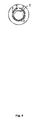
- the physiological water circulating in the communication channel 19 with the irrigation channel 5, figure 5 , or in the communication channel 21 with the suction channel 9, figure 6 enters the fluid compartment 39a of the first pressure detector 18a, open on the communication path 13,15 through the conduit 41a and closed by the membrane 37a.
- the latter 37a is deformed according to the pressure of the physiological water in the communication channel 19 or 21.
- the physiological water flowing in the irrigation channel 5, suction respectively 9, enters, via the bypass route 27 and the blind port 29, into the fluid compartment 39b of the second detector 18b, open on the blind way 29 through the conduit 41b and closed by the membrane 37b.
- the latter is deformed according to the pressure of the physiological water in the blind way 29.
- Unrepresented capillaries are connected to connection jacks 47 of the transmission chambers 37a, 37b for transmitting the variations of the air pressure prevailing in the chambers 35a, 35b to unrepresented sensors and to determine the pressure of the water. physiological in the communication path 19, 21 and in the blind way 29.
- the endoscopy system according to the invention is particularly useful in the arthroscopy of the joints, such as those of the knee or the shoulder.
- the invention applies to a cannula that does not include a channel dedicated to the detection of the pressure in the joint, to advantageously reduce the outer diameter of the cannula to make it less traumatic when it is put into operation. place by the surgeon.
- the invention also applies to an endoscopy system where the cannula comprises a channel dedicated to pressure.
- the connecting ring is therefore modified so that the bypass channel communicates with the channel dedicated to the pressure and the connector is mounted on the connecting ring to communicate the blind way with the bypass path.
Landscapes
- Health & Medical Sciences (AREA)
- Life Sciences & Earth Sciences (AREA)
- Surgery (AREA)
- Medical Informatics (AREA)
- Animal Behavior & Ethology (AREA)
- Optics & Photonics (AREA)
- Pathology (AREA)
- Radiology & Medical Imaging (AREA)
- Biophysics (AREA)
- Engineering & Computer Science (AREA)
- Biomedical Technology (AREA)
- Heart & Thoracic Surgery (AREA)
- Physics & Mathematics (AREA)
- Molecular Biology (AREA)
- Nuclear Medicine, Radiotherapy & Molecular Imaging (AREA)
- General Health & Medical Sciences (AREA)
- Public Health (AREA)
- Veterinary Medicine (AREA)
- Orthopedic Medicine & Surgery (AREA)
- Physical Education & Sports Medicine (AREA)
- Endoscopes (AREA)
- Instruments For Viewing The Inside Of Hollow Bodies (AREA)
- Measuring Fluid Pressure (AREA)
- Measuring Pulse, Heart Rate, Blood Pressure Or Blood Flow (AREA)
- Measuring And Recording Apparatus For Diagnosis (AREA)
- Arrangements For Transmission Of Measured Signals (AREA)
- Ultra Sonic Daignosis Equipment (AREA)
Claims (6)
- Endoskopiesystem mit einer Kanüle (1) zur Aufnahme eines Endoskops (3) und zum Bilden eines Irrigationskanals (5) beziehungsweise eines Aspirationskanals (9) zwischen der Kanüle und dem Endoskop, der für die Beförderung eines Irrigationsfluids beziehungsweise Aspirationsfluids vorgesehen ist, mit einem Anschlussring (11), der um die Kanüle (1) herum angeordnet ist und einen Anschlusskanal (13, 15) zu dem Irrigationskanal (5) beziehungsweise zu dem Aspirationskanal (9) aufweist, und mit einem Verbindungsstück (17), das an dem Anschlussring (11) angebracht ist und über einen Verbindungskanal (19, 21) zu dem Anschlusskanal (13, 15) sowie über einen ersten Druckdetektor (18a) zum Detektieren eines Drucks in dem Verbindungskanal (19, 21) verfügt, dadurch gekennzeichnet, dass der Anschlussring (11) über einen Abzweigkanal (27) verfügt, der mit den Irrigationskanal (5) beziehungsweise mit dem Aspirationskanal (9) verbunden ist, und dass das Verbindungsstück (17) über einen blinden Kanal (29) verfügt, der mit dem Abzweigkanal (27) und mit einem zweiten Druckdetektor (18b) zum Detektieren eines Drucks in dem blinden Kanal (29) verbunden ist.
- Endoskopiesystem nach Anspruch 1, dadurch gekennzeichnet, dass der Abzweigkanal (27) in Bezug auf den Transport des Fluids zur Irrigation strömungsabwärts von dem Anschlusskanal (13) zu dem Irrigationskanal (5) beziehungsweise in Bezug auf den Transport des Fluids zur Aspiration strömungsaufwärts von dem Anschlusskanal (15) zu dem Aspirationskanal (9) angeordnet ist und dass ein Irrigationshahn (23) zum Schließen oder Öffnen des Anschlusskanals (13) zu dem Irrigationskanal (5) strömungsaufwärts des Abzweigkanals (27) vorgesehen ist beziehungsweise ein Aspirationshahn (25) zum Schließen oder Öffnen des Anschlusskanals (15) zu dem Aspirationskanal (9) strömungsabwärts des Abzweigkanals (27) vorgesehen ist.
- Verbindungsstück für ein Endoskopiesystem nach Anspruch 1 oder 2, das über einen Verbindungskanal (19, 21) und über einen Druckdetektor (18a) zum Detektieren des Drucks in dem Verbindungskanal (19, 21) verfügt, dadurch gekennzeichnet, dass es einen blinden Kanal (29) und einen zweiten Druckdetektor (18b) zum Detektieren des Drucks in dem blinden Kanal (29) aufweist.
- Verbindungsstück nach Anspruch 3, dadurch gekennzeichnet, dass es über einen zweiten Verbindungskanal (19, 21) verfügt.
- Verbindungsstück nach Anspruch 4, dadurch gekennzeichnet, dass der Abzweigkanal zwischen den beiden Verbindungskanälen (19, 21) angeordnet ist.
- Verbindungsstück nach Anspruch 4 oder 5, dadurch gekennzeichnet, dass die Druckdetektoren (18a, 18b) Membrandetektoren sind.
Applications Claiming Priority (2)
| Application Number | Priority Date | Filing Date | Title |
|---|---|---|---|
| FR0402238A FR2867054B1 (fr) | 2004-03-04 | 2004-03-04 | Systeme d'endoscopie et connecteur a detecteur de pression destine a un tel systeme |
| PCT/CH2005/000122 WO2005084523A1 (fr) | 2004-03-04 | 2005-03-02 | Systeme d'endoscopie et connecteur a detecteur de pression destine a un tel systeme |
Publications (2)
| Publication Number | Publication Date |
|---|---|
| EP1720440A1 EP1720440A1 (de) | 2006-11-15 |
| EP1720440B1 true EP1720440B1 (de) | 2011-05-04 |
Family
ID=34855040
Family Applications (2)
| Application Number | Title | Priority Date | Filing Date |
|---|---|---|---|
| EP05706541A Expired - Lifetime EP1720440B1 (de) | 2004-03-04 | 2005-03-02 | Endoskopie-system und druckübermittelnder verbinder für dieses system |
| EP05706546A Expired - Lifetime EP1720441B1 (de) | 2004-03-04 | 2005-03-03 | Druckübermittelnder verbinder für ein endoskopiesystem |
Family Applications After (1)
| Application Number | Title | Priority Date | Filing Date |
|---|---|---|---|
| EP05706546A Expired - Lifetime EP1720441B1 (de) | 2004-03-04 | 2005-03-03 | Druckübermittelnder verbinder für ein endoskopiesystem |
Country Status (14)
| Country | Link |
|---|---|
| US (4) | US7892167B2 (de) |
| EP (2) | EP1720440B1 (de) |
| JP (2) | JP4758414B2 (de) |
| KR (2) | KR101106306B1 (de) |
| CN (2) | CN100462043C (de) |
| AT (2) | ATE507759T1 (de) |
| AU (2) | AU2005219999B2 (de) |
| CA (2) | CA2558066C (de) |
| DE (2) | DE602005027816D1 (de) |
| DK (2) | DK1720440T3 (de) |
| FR (1) | FR2867054B1 (de) |
| NO (2) | NO336677B1 (de) |
| PT (2) | PT1720440E (de) |
| WO (2) | WO2005084523A1 (de) |
Families Citing this family (16)
| Publication number | Priority date | Publication date | Assignee | Title |
|---|---|---|---|---|
| FR2867054B1 (fr) * | 2004-03-04 | 2006-09-15 | Future Medical System | Systeme d'endoscopie et connecteur a detecteur de pression destine a un tel systeme |
| KR100811588B1 (ko) | 2007-03-26 | 2008-03-11 | 한국화학연구원 | 자동비디오점적기 |
| CN101194824B (zh) * | 2008-01-08 | 2011-07-20 | 潘西川 | 智能型内窥镜 |
| DE102008026457A1 (de) * | 2008-06-03 | 2009-12-10 | Karl Storz Gmbh & Co. Kg | Medizinisches Instrument |
| CN101664301B (zh) * | 2008-09-02 | 2011-04-20 | 光峰科技股份有限公司 | 具有金属埋植接点的内视镜胶囊 |
| WO2010137024A1 (en) * | 2009-05-28 | 2010-12-02 | Given Imaging Ltd. | Apparatus for delivery of autonomous in-vivo capsules |
| EP2459050A1 (de) * | 2009-07-29 | 2012-06-06 | FUJIFILM Corporation | Antreibbare vorrichtung mit passiver grössenveränderungsfunktion |
| US8465421B2 (en) | 2009-12-14 | 2013-06-18 | C2Cure Inc. | Endoscope with an improved working channel |
| KR101157170B1 (ko) * | 2011-07-01 | 2012-06-20 | 박종은 | 내시경용 약물 투여장치 |
| US9603990B2 (en) | 2012-04-05 | 2017-03-28 | Stryker Corporation | Cassette for a surgical fluid management pump system |
| US9492071B2 (en) | 2012-04-05 | 2016-11-15 | Stryker Corporation | In-joint sensor for a surgical fluid management pump system |
| US9289110B2 (en) | 2012-04-05 | 2016-03-22 | Stryker Corporation | Control for surgical fluid management pump system |
| TWI572311B (zh) * | 2012-11-29 | 2017-03-01 | 喉罩股份有限公司 | 咽喉鏡裝置 |
| WO2015066294A1 (en) * | 2013-10-30 | 2015-05-07 | Faculty Physicians And Surgeons Of Loma Linda University School Of Medicine | Controlled pressure endoscopic and percutaneous surgery |
| US20170106199A1 (en) | 2015-10-16 | 2017-04-20 | Brady L. WOOLFORD | Integrated pump control for dynamic control of plasma field |
| CN111511261B (zh) * | 2017-12-22 | 2023-07-04 | 奥林巴斯株式会社 | 插入设备 |
Family Cites Families (28)
| Publication number | Priority date | Publication date | Assignee | Title |
|---|---|---|---|---|
| US4132227A (en) * | 1974-08-08 | 1979-01-02 | Winter & Ibe | Urological endoscope particularly resectoscope |
| US4086815A (en) | 1975-07-24 | 1978-05-02 | Fuji Electric Co., Ltd. | Device for use in sensing pressures |
| JPS56163626A (en) * | 1980-05-21 | 1981-12-16 | Olympus Optical Co | Rejectscope |
| US4971034A (en) * | 1985-01-16 | 1990-11-20 | Asahi Kogaku Kogyo Kabushiki Kaisha | Body cavity pressure adjusting device for endoscope and laser medical treatment apparatus including body cavity pressure adjusting device |
| DE3918142A1 (de) * | 1989-05-31 | 1990-12-13 | Wiest Peter P | Druckmessvorrichtung fuer in leitungen stroemende fluide |
| DE3932443C1 (de) | 1989-09-28 | 1990-12-20 | Endress U. Hauser Gmbh U. Co, 7864 Maulburg, De | |
| US5037386A (en) | 1989-11-17 | 1991-08-06 | Minnesota Mining And Manufacturing Company | Pressure sensing scope cannula |
| US5191878A (en) * | 1990-04-12 | 1993-03-09 | Olympus Optical Co., Ltd. | Endoscope device |
| JPH0422327A (ja) * | 1990-05-18 | 1992-01-27 | Olympus Optical Co Ltd | 内視鏡用管路制御装置 |
| US5443801A (en) * | 1990-07-20 | 1995-08-22 | Kew Import/Export Inc. | Endoscope cleaner/sterilizer |
| EP0692266B1 (de) * | 1991-08-21 | 2000-03-22 | Smith & Nephew, Inc. | Flüssigkeitsbehandlungssystem |
| US5483835A (en) * | 1993-10-13 | 1996-01-16 | Saturn Electronics & Engineering, Inc. | Oil pressure sender unit with reinforced diaphragm |
| US5460490A (en) * | 1994-05-19 | 1995-10-24 | Linvatec Corporation | Multi-purpose irrigation/aspiration pump system |
| US5634880A (en) * | 1995-05-22 | 1997-06-03 | Johnson & Johnson Medical, Inc. | Endoscope pressure equalization system and method |
| KR19990008150A (ko) * | 1996-03-07 | 1999-01-25 | 노무라마사나리 | 압력센서모듈 |
| US5836909A (en) * | 1996-09-13 | 1998-11-17 | Cosmescu; Ioan | Automatic fluid control system for use in open and laparoscopic laser surgery and electrosurgery and method therefor |
| US5796007A (en) * | 1996-09-23 | 1998-08-18 | Data Instruments, Inc. | Differential pressure transducer |
| CN2285637Y (zh) * | 1996-11-01 | 1998-07-08 | 杭州好克光电仪器有限公司 | 电切镜 |
| US5810770A (en) * | 1996-12-13 | 1998-09-22 | Stryker Corporation | Fluid management pump system for surgical procedures |
| JPH10309254A (ja) | 1997-05-13 | 1998-11-24 | Olympus Optical Co Ltd | 内視鏡洗滌消毒装置 |
| US6086542A (en) | 1997-07-01 | 2000-07-11 | Linvatec Corporation | Pressure sensing input/output scope sheath |
| US6055453A (en) * | 1997-08-01 | 2000-04-25 | Genetronics, Inc. | Apparatus for addressing needle array electrodes for electroporation therapy |
| KR100328420B1 (ko) * | 1999-07-30 | 2002-03-13 | 김춘영 | 의료용 내시경 세척장치 및 그 세척방법 |
| JP2001242024A (ja) * | 2000-02-25 | 2001-09-07 | Seiko Instruments Inc | 体内埋込式圧力感知装置並びに該感知装置を用いた圧力検出システム及び圧力調整システム |
| DE20006247U1 (de) * | 2000-04-05 | 2000-08-17 | Joist, Alexander, Dr., 49808 Lingen | Kernbohrer, insbesondere Markraumbohrer für Röhrenknochen |
| KR20020036795A (ko) * | 2002-02-06 | 2002-05-16 | (주)메드온 | 내시경 세정장치 및 방법 |
| US7150713B2 (en) * | 2003-10-16 | 2006-12-19 | Smith & Nephew, Inc. | Endoscopic device |
| FR2867054B1 (fr) * | 2004-03-04 | 2006-09-15 | Future Medical System | Systeme d'endoscopie et connecteur a detecteur de pression destine a un tel systeme |
-
2004
- 2004-03-04 FR FR0402238A patent/FR2867054B1/fr not_active Expired - Fee Related
-
2005
- 2005-03-02 AT AT05706541T patent/ATE507759T1/de not_active IP Right Cessation
- 2005-03-02 CA CA2558066A patent/CA2558066C/en not_active Expired - Fee Related
- 2005-03-02 EP EP05706541A patent/EP1720440B1/de not_active Expired - Lifetime
- 2005-03-02 CN CNB2005800066794A patent/CN100462043C/zh not_active Expired - Fee Related
- 2005-03-02 KR KR1020067020233A patent/KR101106306B1/ko not_active Expired - Fee Related
- 2005-03-02 DK DK05706541.9T patent/DK1720440T3/da active
- 2005-03-02 US US10/591,441 patent/US7892167B2/en active Active
- 2005-03-02 DE DE602005027816T patent/DE602005027816D1/de not_active Expired - Lifetime
- 2005-03-02 JP JP2007501090A patent/JP4758414B2/ja not_active Expired - Fee Related
- 2005-03-02 AU AU2005219999A patent/AU2005219999B2/en not_active Ceased
- 2005-03-02 PT PT05706541T patent/PT1720440E/pt unknown
- 2005-03-02 WO PCT/CH2005/000122 patent/WO2005084523A1/fr not_active Ceased
- 2005-03-03 JP JP2007501092A patent/JP4712790B2/ja not_active Expired - Lifetime
- 2005-03-03 CN CNB2005800066775A patent/CN100484462C/zh not_active Expired - Fee Related
- 2005-03-03 DE DE602005014206T patent/DE602005014206D1/de not_active Expired - Lifetime
- 2005-03-03 CA CA2558068A patent/CA2558068C/en not_active Expired - Fee Related
- 2005-03-03 WO PCT/CH2005/000127 patent/WO2005084524A1/fr not_active Ceased
- 2005-03-03 AT AT05706546T patent/ATE429845T1/de not_active IP Right Cessation
- 2005-03-03 DK DK05706546T patent/DK1720441T3/da active
- 2005-03-03 EP EP05706546A patent/EP1720441B1/de not_active Expired - Lifetime
- 2005-03-03 PT PT05706546T patent/PT1720441E/pt unknown
- 2005-03-03 KR KR1020067020234A patent/KR101106305B1/ko not_active Expired - Fee Related
- 2005-03-03 US US10/591,753 patent/US7526960B2/en not_active Expired - Lifetime
- 2005-03-03 AU AU2005220001A patent/AU2005220001B2/en not_active Ceased
-
2006
- 2006-09-13 NO NO20064147A patent/NO336677B1/no not_active IP Right Cessation
- 2006-09-13 NO NO20064141A patent/NO336491B1/no not_active IP Right Cessation
-
2011
- 2011-01-13 US US13/005,908 patent/US8317687B2/en not_active Expired - Lifetime
-
2012
- 2012-10-19 US US13/656,394 patent/US9237838B2/en not_active Expired - Lifetime
Also Published As
Similar Documents
| Publication | Publication Date | Title |
|---|---|---|
| US8317687B2 (en) | Endoscopy system and a pressure transmitting connector for said system | |
| US9393397B2 (en) | Diaphragm pressure pod for medical fluids | |
| CN102421465A (zh) | 引流管装置以及耦接单元 | |
| FR2748564A1 (fr) | Dispositif de mesure de la pression d'un liquide circulant dans une tubulure vers ou hors du corps humain | |
| FR2625104A1 (fr) | Systeme d'irrigation destine a etre utilise pendant une arthroscopie | |
| ITMO20040082A1 (it) | Connettore per una linea di fluido di un circuito extacorporeo | |
| FR2928838A1 (fr) | Dispositif de raccordement/protection de capteur, en particulier pour des lignes biomedicales d'hemodialyse | |
| FR2952682A1 (fr) | Dispositif pour surveiller un prelevement a l'aide d'une pompe a piston. | |
| FR2948085A1 (fr) | Dispositif de freinage assiste pour vehicule automobile, raccord a deux passages de fluide, et raccord equipant un dispositif de freinage assiste |
Legal Events
| Date | Code | Title | Description |
|---|---|---|---|
| PUAI | Public reference made under article 153(3) epc to a published international application that has entered the european phase |
Free format text: ORIGINAL CODE: 0009012 |
|
| 17P | Request for examination filed |
Effective date: 20060907 |
|
| AK | Designated contracting states |
Kind code of ref document: A1 Designated state(s): AT BE BG CH CY CZ DE DK EE ES FI FR GB GR HU IE IS IT LI LT LU MC NL PL PT RO SE SI SK TR |
|
| DAX | Request for extension of the european patent (deleted) | ||
| RIN1 | Information on inventor provided before grant (corrected) |
Inventor name: JANIN, PATRICK Inventor name: PASCUAL, THIERRY Inventor name: DIAS, ARMANDO Inventor name: FRANCISCO, ANDRE |
|
| GRAP | Despatch of communication of intention to grant a patent |
Free format text: ORIGINAL CODE: EPIDOSNIGR1 |
|
| RIN1 | Information on inventor provided before grant (corrected) |
Inventor name: PASCAL, THIERRY Inventor name: FRANCISCO, ANDRE Inventor name: JANIN, PATRICK Inventor name: DIAS, ARMANDO |
|
| GRAS | Grant fee paid |
Free format text: ORIGINAL CODE: EPIDOSNIGR3 |
|
| GRAA | (expected) grant |
Free format text: ORIGINAL CODE: 0009210 |
|
| AK | Designated contracting states |
Kind code of ref document: B1 Designated state(s): AT BE BG CH CY CZ DE DK EE ES FI FR GB GR HU IE IS IT LI LT LU MC NL PL PT RO SE SI SK TR |
|
| REG | Reference to a national code |
Ref country code: GB Ref legal event code: FG4D Free format text: NOT ENGLISH |
|
| REG | Reference to a national code |
Ref country code: CH Ref legal event code: EP |
|
| REG | Reference to a national code |
Ref country code: IE Ref legal event code: FG4D Free format text: LANGUAGE OF EP DOCUMENT: FRENCH |
|
| REF | Corresponds to: |
Ref document number: 602005027816 Country of ref document: DE Date of ref document: 20110616 Kind code of ref document: P |
|
| REG | Reference to a national code |
Ref country code: DE Ref legal event code: R096 Ref document number: 602005027816 Country of ref document: DE Effective date: 20110616 |
|
| REG | Reference to a national code |
Ref country code: PT Ref legal event code: SC4A Free format text: AVAILABILITY OF NATIONAL TRANSLATION Effective date: 20110802 |
|
| REG | Reference to a national code |
Ref country code: DK Ref legal event code: T3 |
|
| REG | Reference to a national code |
Ref country code: SE Ref legal event code: TRGR |
|
| REG | Reference to a national code |
Ref country code: NL Ref legal event code: VDEP Effective date: 20110504 |
|
| REG | Reference to a national code |
Ref country code: CH Ref legal event code: PFA Owner name: FMS FUTURE MEDICAL SYSTEM SA Free format text: FUTURE MEDICAL SYSTEM S.A.#CHEMIN DU GRAND PUITS 38#1217 MEYRIN (CH) -TRANSFER TO- FMS FUTURE MEDICAL SYSTEM SA#C/O MEDOS INTERNATIONAL SARL RUE GIRARDET, 29#2400 LE LOCLE (CH) Ref country code: CH Ref legal event code: NV Representative=s name: MOINAS & SAVOYE SA |
|
| PG25 | Lapsed in a contracting state [announced via postgrant information from national office to epo] |
Ref country code: LT Free format text: LAPSE BECAUSE OF FAILURE TO SUBMIT A TRANSLATION OF THE DESCRIPTION OR TO PAY THE FEE WITHIN THE PRESCRIBED TIME-LIMIT Effective date: 20110504 |
|
| PG25 | Lapsed in a contracting state [announced via postgrant information from national office to epo] |
Ref country code: ES Free format text: LAPSE BECAUSE OF FAILURE TO SUBMIT A TRANSLATION OF THE DESCRIPTION OR TO PAY THE FEE WITHIN THE PRESCRIBED TIME-LIMIT Effective date: 20110815 Ref country code: GR Free format text: LAPSE BECAUSE OF FAILURE TO SUBMIT A TRANSLATION OF THE DESCRIPTION OR TO PAY THE FEE WITHIN THE PRESCRIBED TIME-LIMIT Effective date: 20110805 Ref country code: SI Free format text: LAPSE BECAUSE OF FAILURE TO SUBMIT A TRANSLATION OF THE DESCRIPTION OR TO PAY THE FEE WITHIN THE PRESCRIBED TIME-LIMIT Effective date: 20110504 Ref country code: AT Free format text: LAPSE BECAUSE OF FAILURE TO SUBMIT A TRANSLATION OF THE DESCRIPTION OR TO PAY THE FEE WITHIN THE PRESCRIBED TIME-LIMIT Effective date: 20110504 Ref country code: IS Free format text: LAPSE BECAUSE OF FAILURE TO SUBMIT A TRANSLATION OF THE DESCRIPTION OR TO PAY THE FEE WITHIN THE PRESCRIBED TIME-LIMIT Effective date: 20110904 Ref country code: CY Free format text: LAPSE BECAUSE OF FAILURE TO SUBMIT A TRANSLATION OF THE DESCRIPTION OR TO PAY THE FEE WITHIN THE PRESCRIBED TIME-LIMIT Effective date: 20110504 Ref country code: FI Free format text: LAPSE BECAUSE OF FAILURE TO SUBMIT A TRANSLATION OF THE DESCRIPTION OR TO PAY THE FEE WITHIN THE PRESCRIBED TIME-LIMIT Effective date: 20110504 |
|
| RAP2 | Party data changed (patent owner data changed or rights of a patent transferred) |
Owner name: FUTURE MEDICAL SYSTEM S.A. |
|
| PG25 | Lapsed in a contracting state [announced via postgrant information from national office to epo] |
Ref country code: NL Free format text: LAPSE BECAUSE OF FAILURE TO SUBMIT A TRANSLATION OF THE DESCRIPTION OR TO PAY THE FEE WITHIN THE PRESCRIBED TIME-LIMIT Effective date: 20110504 |
|
| RAP2 | Party data changed (patent owner data changed or rights of a patent transferred) |
Owner name: FUTURE MEDICAL SYSTEM S.A. |
|
| PG25 | Lapsed in a contracting state [announced via postgrant information from national office to epo] |
Ref country code: EE Free format text: LAPSE BECAUSE OF FAILURE TO SUBMIT A TRANSLATION OF THE DESCRIPTION OR TO PAY THE FEE WITHIN THE PRESCRIBED TIME-LIMIT Effective date: 20110504 Ref country code: CZ Free format text: LAPSE BECAUSE OF FAILURE TO SUBMIT A TRANSLATION OF THE DESCRIPTION OR TO PAY THE FEE WITHIN THE PRESCRIBED TIME-LIMIT Effective date: 20110504 |
|
| REG | Reference to a national code |
Ref country code: DE Ref legal event code: R082 Ref document number: 602005027816 Country of ref document: DE Representative=s name: RACKETTE PARTNERSCHAFT PATENTANWAELTE, DE |
|
| PG25 | Lapsed in a contracting state [announced via postgrant information from national office to epo] |
Ref country code: SK Free format text: LAPSE BECAUSE OF FAILURE TO SUBMIT A TRANSLATION OF THE DESCRIPTION OR TO PAY THE FEE WITHIN THE PRESCRIBED TIME-LIMIT Effective date: 20110504 Ref country code: PL Free format text: LAPSE BECAUSE OF FAILURE TO SUBMIT A TRANSLATION OF THE DESCRIPTION OR TO PAY THE FEE WITHIN THE PRESCRIBED TIME-LIMIT Effective date: 20110504 Ref country code: RO Free format text: LAPSE BECAUSE OF FAILURE TO SUBMIT A TRANSLATION OF THE DESCRIPTION OR TO PAY THE FEE WITHIN THE PRESCRIBED TIME-LIMIT Effective date: 20110504 |
|
| PLBE | No opposition filed within time limit |
Free format text: ORIGINAL CODE: 0009261 |
|
| STAA | Information on the status of an ep patent application or granted ep patent |
Free format text: STATUS: NO OPPOSITION FILED WITHIN TIME LIMIT |
|
| RAP2 | Party data changed (patent owner data changed or rights of a patent transferred) |
Owner name: FUTURE MEDICAL SYSTEM S.A. |
|
| REG | Reference to a national code |
Ref country code: DE Ref legal event code: R082 Ref document number: 602005027816 Country of ref document: DE Representative=s name: RACKETTE PARTNERSCHAFT PATENTANWAELTE, DE Effective date: 20120206 Ref country code: DE Ref legal event code: R081 Ref document number: 602005027816 Country of ref document: DE Owner name: FUTURE MEDICAL SYSTEM S.A., CH Free format text: FORMER OWNER: FUTURE MEDICAL SYSTEM S.A., MEYRIN, CH Effective date: 20120206 Ref country code: DE Ref legal event code: R082 Ref document number: 602005027816 Country of ref document: DE Representative=s name: RACKETTE PATENTANWAELTE PARTG MBB, DE Effective date: 20120206 |
|
| 26N | No opposition filed |
Effective date: 20120207 |
|
| REG | Reference to a national code |
Ref country code: DE Ref legal event code: R097 Ref document number: 602005027816 Country of ref document: DE Effective date: 20120207 |
|
| BERE | Be: lapsed |
Owner name: FUTURE MEDICAL SYSTEM S.A. Effective date: 20120331 |
|
| PG25 | Lapsed in a contracting state [announced via postgrant information from national office to epo] |
Ref country code: MC Free format text: LAPSE BECAUSE OF NON-PAYMENT OF DUE FEES Effective date: 20120331 |
|
| PG25 | Lapsed in a contracting state [announced via postgrant information from national office to epo] |
Ref country code: BE Free format text: LAPSE BECAUSE OF NON-PAYMENT OF DUE FEES Effective date: 20120331 |
|
| PG25 | Lapsed in a contracting state [announced via postgrant information from national office to epo] |
Ref country code: BG Free format text: LAPSE BECAUSE OF FAILURE TO SUBMIT A TRANSLATION OF THE DESCRIPTION OR TO PAY THE FEE WITHIN THE PRESCRIBED TIME-LIMIT Effective date: 20110804 |
|
| PG25 | Lapsed in a contracting state [announced via postgrant information from national office to epo] |
Ref country code: TR Free format text: LAPSE BECAUSE OF FAILURE TO SUBMIT A TRANSLATION OF THE DESCRIPTION OR TO PAY THE FEE WITHIN THE PRESCRIBED TIME-LIMIT Effective date: 20110504 |
|
| PG25 | Lapsed in a contracting state [announced via postgrant information from national office to epo] |
Ref country code: LU Free format text: LAPSE BECAUSE OF NON-PAYMENT OF DUE FEES Effective date: 20120302 |
|
| PG25 | Lapsed in a contracting state [announced via postgrant information from national office to epo] |
Ref country code: HU Free format text: LAPSE BECAUSE OF FAILURE TO SUBMIT A TRANSLATION OF THE DESCRIPTION OR TO PAY THE FEE WITHIN THE PRESCRIBED TIME-LIMIT Effective date: 20050302 |
|
| PGFP | Annual fee paid to national office [announced via postgrant information from national office to epo] |
Ref country code: DK Payment date: 20150310 Year of fee payment: 11 Ref country code: PT Payment date: 20150302 Year of fee payment: 11 |
|
| PGFP | Annual fee paid to national office [announced via postgrant information from national office to epo] |
Ref country code: SE Payment date: 20150311 Year of fee payment: 11 |
|
| REG | Reference to a national code |
Ref country code: FR Ref legal event code: PLFP Year of fee payment: 12 |
|
| REG | Reference to a national code |
Ref country code: DK Ref legal event code: EBP Effective date: 20160331 |
|
| REG | Reference to a national code |
Ref country code: SE Ref legal event code: EUG |
|
| PG25 | Lapsed in a contracting state [announced via postgrant information from national office to epo] |
Ref country code: PT Free format text: LAPSE BECAUSE OF NON-PAYMENT OF DUE FEES Effective date: 20160902 Ref country code: SE Free format text: LAPSE BECAUSE OF NON-PAYMENT OF DUE FEES Effective date: 20160303 |
|
| REG | Reference to a national code |
Ref country code: CH Ref legal event code: PFA Owner name: FMS FUTURE MEDICAL SYSTEM SA, CH Free format text: FORMER OWNER: FMS FUTURE MEDICAL SYSTEM SA, CH |
|
| REG | Reference to a national code |
Ref country code: FR Ref legal event code: PLFP Year of fee payment: 13 |
|
| PG25 | Lapsed in a contracting state [announced via postgrant information from national office to epo] |
Ref country code: DK Free format text: LAPSE BECAUSE OF NON-PAYMENT OF DUE FEES Effective date: 20160331 |
|
| REG | Reference to a national code |
Ref country code: FR Ref legal event code: PLFP Year of fee payment: 14 |
|
| PGFP | Annual fee paid to national office [announced via postgrant information from national office to epo] |
Ref country code: GB Payment date: 20190227 Year of fee payment: 15 Ref country code: IE Payment date: 20190311 Year of fee payment: 15 Ref country code: IT Payment date: 20190326 Year of fee payment: 15 Ref country code: DE Payment date: 20190219 Year of fee payment: 15 Ref country code: CH Payment date: 20190314 Year of fee payment: 15 |
|
| PGFP | Annual fee paid to national office [announced via postgrant information from national office to epo] |
Ref country code: FR Payment date: 20190213 Year of fee payment: 15 |
|
| REG | Reference to a national code |
Ref country code: DE Ref legal event code: R119 Ref document number: 602005027816 Country of ref document: DE |
|
| REG | Reference to a national code |
Ref country code: CH Ref legal event code: PL |
|
| PG25 | Lapsed in a contracting state [announced via postgrant information from national office to epo] |
Ref country code: LI Free format text: LAPSE BECAUSE OF NON-PAYMENT OF DUE FEES Effective date: 20200331 Ref country code: IE Free format text: LAPSE BECAUSE OF NON-PAYMENT OF DUE FEES Effective date: 20200302 Ref country code: FR Free format text: LAPSE BECAUSE OF NON-PAYMENT OF DUE FEES Effective date: 20200331 Ref country code: DE Free format text: LAPSE BECAUSE OF NON-PAYMENT OF DUE FEES Effective date: 20201001 Ref country code: CH Free format text: LAPSE BECAUSE OF NON-PAYMENT OF DUE FEES Effective date: 20200331 |
|
| GBPC | Gb: european patent ceased through non-payment of renewal fee |
Effective date: 20200302 |
|
| PG25 | Lapsed in a contracting state [announced via postgrant information from national office to epo] |
Ref country code: GB Free format text: LAPSE BECAUSE OF NON-PAYMENT OF DUE FEES Effective date: 20200302 |
|
| PG25 | Lapsed in a contracting state [announced via postgrant information from national office to epo] |
Ref country code: IT Free format text: LAPSE BECAUSE OF NON-PAYMENT OF DUE FEES Effective date: 20200302 |