EP1720581B1 - Sterilisateur a uv de pieces a main dentaires - Google Patents
Sterilisateur a uv de pieces a main dentaires Download PDFInfo
- Publication number
- EP1720581B1 EP1720581B1 EP05726290A EP05726290A EP1720581B1 EP 1720581 B1 EP1720581 B1 EP 1720581B1 EP 05726290 A EP05726290 A EP 05726290A EP 05726290 A EP05726290 A EP 05726290A EP 1720581 B1 EP1720581 B1 EP 1720581B1
- Authority
- EP
- European Patent Office
- Prior art keywords
- sterilizer
- ultraviolet
- handpiece
- casing assembly
- barrier
- Prior art date
- Legal status (The legal status is an assumption and is not a legal conclusion. Google has not performed a legal analysis and makes no representation as to the accuracy of the status listed.)
- Expired - Lifetime
Links
Images




Classifications
-
- A—HUMAN NECESSITIES
- A61—MEDICAL OR VETERINARY SCIENCE; HYGIENE
- A61L—METHODS OR APPARATUS FOR STERILISING MATERIALS OR OBJECTS IN GENERAL; DISINFECTION, STERILISATION OR DEODORISATION OF AIR; CHEMICAL ASPECTS OF BANDAGES, DRESSINGS, ABSORBENT PADS OR SURGICAL ARTICLES; MATERIALS FOR BANDAGES, DRESSINGS, ABSORBENT PADS OR SURGICAL ARTICLES
- A61L2/00—Disinfection or sterilisation of materials or objects, in general; Accessories therefor
- A61L2/24—Apparatus using programmed or automatic operation
-
- A—HUMAN NECESSITIES
- A61—MEDICAL OR VETERINARY SCIENCE; HYGIENE
- A61L—METHODS OR APPARATUS FOR STERILISING MATERIALS OR OBJECTS IN GENERAL; DISINFECTION, STERILISATION OR DEODORISATION OF AIR; CHEMICAL ASPECTS OF BANDAGES, DRESSINGS, ABSORBENT PADS OR SURGICAL ARTICLES; MATERIALS FOR BANDAGES, DRESSINGS, ABSORBENT PADS OR SURGICAL ARTICLES
- A61L2/00—Disinfection or sterilisation of materials or objects, in general; Accessories therefor
- A61L2/02—Disinfection or sterilisation of materials or objects, in general; Accessories therefor using physical processes
- A61L2/08—Radiation
- A61L2/10—Ultraviolet [UV] radiation
-
- A—HUMAN NECESSITIES
- A61—MEDICAL OR VETERINARY SCIENCE; HYGIENE
- A61C—DENTISTRY; APPARATUS OR METHODS FOR ORAL OR DENTAL HYGIENE
- A61C19/00—Dental auxiliary appliances
- A61C19/002—Cleaning devices specially adapted for dental instruments
Definitions
- the present invention relates to a sterilizer for a handpiece contaminated by contacting dirt such as blood or spit, which contains germs or bacteria while being put into a patient's mouth and treating, at a dental clinic.
- tweezers tweezers, probes, mirrors, and handpieces are used to treat teeth or gums inside a mouth.
- These appliances are easily contaminated by germs or bacteria contained in blood, spit or tissues of patients, so that preventing other patients from being infected with germs or bacteria by sterilizing the contaminated appliances thoroughly after use is important.
- Tweezers, probes, and mirrors are relatively cheap, so that it is possible to prepare them in a larger number, gather separately the once used ones, and sterilize using antiseptic solution, or steam or water of high temperature.
- handpieces connected to a pneumatic device or a laser generator, are not so cheap as to be prepared in a large number and changed whenever being used, and equipped with pneumatic motors and lenses, so that it is impossible to sterilize using steam or water of high temperature, making it hard to sterilize.
- FIG. 7 An ultraviolet sterilizer shown in FIG. 7 was developed to sterilize such handpieces.
- the conventional sterilizer 100 like this is equipped in one body with a casing assembly 110 attaching an ultraviolet lamp 112 inside, a drawer 120 withdrawn from and inserted into the front side of the casing assembly 110 to put in dental appliances, and a ventilating fan 130 installed at the inside rear of the case 110 to circulate the inside air through multiple ventilating holes 132.
- the sterilizer 100 has problems in that the handle of the drawer 120 is contaminated since the drawer is opened and closed by a contaminated hand to put the handpiece in the drawer 120, and the hands are contaminated by the handle of the drawer 120 when withdrawing the handpiece after sterilization, therefore the handpiece is contaminated when the handpiece is handled by the contaminated hand, together with a problem radiating ultraviolet rays outside.
- another conventional sterilizer 200 which solved the problems of the drawer type sterilizer is configured in one body, installing an ultraviolet lamp 212 around a quartz tube 220 established horizontally inside the casing assembly 210 and an opening 230 closed by an ultraviolet barrier 234, which has insertion holes 232 incised in a radial shape, at the outer front of the casing assembly 210 installed with the quartz tube 220.
- the ultraviolet barrier 234 is contaminated by the contaminated handpiece when the handpiece is inserted in the sterilizer, and the handpiece is contaminated by the contaminated ultraviolet barrier 234 again when the sterilized handpiece is withdrawn.
- a sterilizer for dental handpieces comprising a sterilizer housing, a holder tube made of transparent quartz glass and a plurality of ultraviolet sterilizer lamps and a door including an ultraviolet barrier is disclosed in US patent 4,772,795 .
- the door mechanism of that sterilizer is operated manually, and the sterilization process is started by pressing a designated switch on the sterilizer housing.
- US patent 6,304,178 B1 discloses an automatic door safety system with optical sensors, which can prevent an obstacle getting near the doors from colliding with the moving doors.
- the present invention has been made in order to solve the above problems occurring in the prior art, and it is an object of the invention to provide an ultraviolet sterilizer for handpieces, which prevents the sterilizer itself from being contaminated by dirt.
- Another object of the invention is to provide an ultraviolet sterilizer, in which, being prevented from contacting with the outside of the sterilizer when withdrawn after sterilization, the sterilized hygienic handpiece is not contaminated by the sterilizer.
- Another object of the invention is to provide a sterilizer for handpieces, which has the effect of aroma therapy at the same time.
- Another object of the invention is to provide a sterilizer for handpieces comprising a file tray, which can be sterilized with dental clinic files put on it by ultraviolet rays.
- Another object of the invention is to provide a sterilizer for handpieces, which prevents ultraviolet rays harmful to the human body from emitting outside the sterilizer.
- the sterilizer for dental handpieces includes: a casing assembly having an opening formed at the front side for coming in and going out of a handpiece; a door configured such that an ultraviolet barrier incised in a radial shape opens and closes the front opening of the casing assembly; a transparent tube installed inside the casing assembly in order to be fluid-communicatively connected with the door to put a handpiece thereon; a sensor installed on the brim of the opening at the front side of the casing assembly; an ultraviolet lamp installed inside the casing assembly; a control circuit for controlling the overall operation of the sterilizer in such a manner that it opens the ultraviolet barrier when it confirms the approach of the handpiece by the sensor, closes the ultraviolet barrier after the handpiece has been entered, turns on the ultraviolet lamp for a pre-determined time, turns off the lamp, opens the ultraviolet barrier again, and closes the ultraviolet barrier after the handpiece has been withdrawn; and
- the control circuit opens the ultraviolet barrier of the door by running the motor.
- the control circuit runs the motor, closing the ultraviolet barrier and turning on the ultraviolet lamp. After a predetermined time, the control circuit turns off the ultraviolet lamp and opens the ultraviolet barrier running the motor in the reverse direction.
- the control circuit further comprises a function which calculates the entering speed of a handpiece by the signal entered from the sensor, and controls the opening speed of the door according to the entering speed of the handpiece.
- the diameter of the tip is short since a handpiece for a dental clinic is inserted deep into a mouth, and the handle held by a user is thick for easy grip.
- the sensor used for the invention may determine the opening and closing speed of the door according to the intensity of the light entered into the optical receiver, and, even when a user puts a handpiece fast into a sterilizer, the opening speed of a barrier also becomes faster, thereby a handpiece not being contacted with a barrier.
- a sterilizer for dental handpiece includes: a casing assembly having an opening formed at the front side for coming in and going out of the handpiece; a door configured such that the ultraviolet barrier incised in a radial shape opens and closes the front opening of the casing assembly, and the ultraviolet barrier is opened while waiting and after completion of sterilization, and the ultraviolet barrier is closed while sterilizing; a transparent tube installed inside the casing assembly in order to be fluid-communicatively connected with the door to put a handpiece thereon; a sensor installed around the transparent tube inside the casing assembly; an ultraviolet lamp installed inside the casing assembly; a control circuit controlling the overall operation of the sterilizer in such a manner that it closes the ultraviolet barrier when the entrance of the handpiece has been confirmed by the sensor, turns on the ultraviolet lamp for a predetermined time and turns off the lamp, and opens the ultraviolet barrier again; and a motor for opening and closing the door in response to a control signal generated from the control circuit.
- the ultraviolet barrier of the sterilizer for a dental handpiece is opened while waiting and after sterilization, so the handpiece can be entered into the sterilizer without touching the ultraviolet barrier.
- the sensor installed around the transparent tube senses the handpiece, and the control circuit closes the ultraviolet barrier running the motor and turns on the ultraviolet lamp. After a predetermined time, the control circuit turns off the lamp and opens the ultraviolet barrier running the motor again.
- the handpiece sterilizer according to the invention is equipped with a reflection protector, in which the transparent tube and the ultraviolet lamp are inserted, inside the casing assembly to protect the leakage of ultraviolet rays.
- the intensity of ultraviolet rays accomplishing the sterilizing objectives is so high that ultraviolet rays leaking out of the sterilizer do harm for human body. Therefore, to prevent in advance ultraviolet rays from leaking through the chasms of the casing assembly of the handpiece, the transparent tube and the ultraviolet lamp are wrapped by the reflection protector.
- minimum 3400 ⁇ W.s/cm 2 and maximum 22000 ⁇ W.s/cm 2 of energy are needed to sterilize virus and germs 100 percent.
- dysentery bacillus is sterilized at 3400 ⁇ W.s/cm 2 of ultraviolet ray energy
- influenza virus is at 6600 ⁇ W.s/cm 2
- tetanus bacillus is at 6600 ⁇ W.s/cm 2 . Therefore, maintaining 22000 ⁇ W.s/cm 2 of irradiation amount of ultraviolet rays inside the sterilizer is effective.
- the handpiece sterilizer according to the invention further comprises a ventilating fan at one side of the casing assembly to exhaust the heat generated by ultraviolet lamps.
- a ventilating fan at one side of the casing assembly to exhaust the heat generated by ultraviolet lamps.
- the handpiece sterilizer according to the invention may further comprise a file tray which has multiple file holes at one side of the casing assembly, which is opened and closed by a cover and can be sterilized with dental files inserted therein.
- the file tray is to insert tools such as a dental drill and sterilize by ultraviolet rays.
- the handpiece sterilizer according to the invention can be configured more including an aromatic tray, which is a drawer putting things in and containing aromas inside, near the ventilating fan.
- aroma therapies are known, which have various curative effects of aromas. Using aromas which have the effect of giving a sense of stability, without additional aromas specially, patients visiting a dental clinic may have mental stability, thereby obtaining favorable effects.
- an ultraviolet sterilizer can be prevented from being contaminated by dirt, and having a handpiece not be contacted with a sterilizer which is apt to be contaminated, a sterilized hygienic handpiece may not be contaminated by a sterilizer after sterilization.
- the ultraviolet sterilizer does not allow the leakage of ultraviolet rays outside, provides an effect of aroma therapy as well, and sterilizes dental files at the same time.
- FIG. 1 shows a perspective view of a handpiece sterilizer according to an example helpful for understanding the invention
- FIG. 2 shows an exploded perspective view of a handpiece sterilizer according to an example helpful for understanding the invention
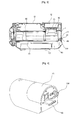
- FIG. 3 shows a cross-section showing the inside of the handpiece sterilizer
- FIG. 4 shows a perspective view of the rear side of the handpiece sterilizer according to the invention
- FIG. 5 is an elevational view showing the state of the door closed
- FIG. 6 is an elevational view showing the state of the door opened
- FIG. 7 shows a conventional ultraviolet sterilizer
- FIG. 8 shows another conventional ultraviolet sterilizer.
- FIG. 1 shows a perspective view of the handpiece sterilizer according to an example helpful for understanding the invention
- FIG. 2 shows an exploded perspective view of the handpiece sterilizer according to an example helpful for understanding the invention
- FIG. 3 shows a cross-section of the inside showing the assembled state
- FIG. 4 shows a perspective view of the rear side of the handpiece sterilizer according to the invention.
- the casing assembly of the handpiece sterilizer 1 according to the invention is injection molded so as to be able to disassemble and assemble an upper casing 10, lower casing 10', and a door cover 20 each other.
- An opening 12 is formed at the front side of the lower casing 10' and the door cover.
- a control circuit 70 is installed at the top side of the lower casing 10' and a ventilating hole is extended to the outside from the rear upper portion, below of which a power outlet and a power switch are installed.
- FIG. 5 and FIG. 6 depicted are the opened and closed states of the door 40, which opens and closes the opening of the casing assembly by the ultraviolet barrier 46 incised in a radial shape.
- the door 40 is composed of a pair of door frames 44, 44', in which circular-arc-type tooth-form parts 44 engaging each other are formed respectively at one side and a frame part 42 on a semicircle which assembles an ultraviolet barrier 46 is formed at the other side, and an ultraviolet barrier 46, which is installed at the frame part 42 on the semicircle of the door frame 44, 44' and incised in a radial shape.
- the upper portion of one door frame 44' is fixed by a hinge so as to be able to move to the front upper portion of the door 40, and the upper portion of the other door 44 is connected to a motor M which is operated by a control circuit.
- the motor starts to operate, according to the operation of the door frame 44 which is connected to the motor, the other door frame 44' is opened or closed by the tooth-form parts engaging each other.
- the ultraviolet barrier 46 is to be lifted so much as not to leak rays when the handpiece is inserted, so that the ultraviolet barrier 46 needs to be formed by a flexible material like silicon or rubber, and incised in radial directions as much as not to allow leakage of rays when lifting the ultraviolet barrier 46.
- the ultraviolet barrier 46 may be installed at the front and the rear side of the frame part 42 on the semicircle in order to prevent leakage of ultraviolet rays more securely.
- the handpiece sterilizer according to the invention is installed inside the casing assembly 10 in order to be fluid-communicatively connected with the door 40, and comprises a transparent tube 50 on which the handpiece is placed.
- the material of the transparent tube 50 should be endurable to heat generated by the ultraviolet lamp and anything transparent that transmits ultraviolet rays well will do.
- Ultraviolet lamps 60 are installed inside the casing assembly 10, and two ultraviolet lamps of 9W capacity, in the present invention, are installed for 1 second sterilization, terminating most of the germs and viruses known up to date.
- the handpiece sterilizer is equipped with a sensor S I which is installed around the opening of the front side of the casing assembly 10 and detects the approach of the handpiece.
- a light emitter and a light receiver are installed in opposite sides around the front opening, and the light receiver receiving the light emitted from the light emitter located at the opposite side.
- the diameter of the tip is short since a handpiece is generally inserted deep into a mouth, and the handle held by a user is thick for easy grip, so that, observing the change of the intensity of the light entering into the light receiver, the ultraviolet barrier 46 is opened fast if the intensity changes fast, and the door of the ultraviolet barrier 46 is opened slowly if the intensity changes slowly.
- the control circuit 70 is also desirable to observe the intensity of the light entering into the light receiver of the sensor, calculate the thickness of the handpiece, and control the speed of the opening speed of the door according to the thickness of the handpiece.
- the control circuit 70 closes the ultraviolet barrier 46, judging that entering process has been completed.
- the control circuit turns on the ultraviolet light 60, turns off the ultraviolet light 60 after a predetermined time, and opens the ultraviolet barrier 46 by starting the motor.
- the control circuit confirms the withdrawal of the handpiece from the sterilizer, and then closes the ultraviolet barrier 46.
- a special sensor also may be installed around the transparent tube 50.
- the casing assembly, the transparent tube, the ultraviolet lamp, and the motor are same compared with the example described above ,but the order of door 40 closing, which is operated by the location of sensors and the control circuit, is different.
- the embodiment has differences, compared with the example described above in that, the door is configured to be open while the ultraviolet barrier incised in the radial shape is waiting and after the completion of the sterilizing, and the sensor is installed around the transparent tube which is inside the casing assembly and detects the approach of the handpiece.
- the difference is in the control circuit, which closes the ultraviolet barrier when the completion of the entering process of the handpiece is detected by the sensor, turns on the ultraviolet lamp for a predetermined time then turns off, and opens the ultraviolet barrier again by starting the motor when sterilization has been completed.
- the ultraviolet barrier of the handpiece sterilizer is open always except while sterilizing, the possibility to contaminate the sterilizer may be completely removed when the handpiece is coming in and going out the sterilizer.
- a reflection protector 80 in which the transparent tube 50 and the ultraviolet lamp 60 is inserted, is installed inside the casing assembly in addition to the handpiece sterilizer explained in the above example and embodiment, ultraviolet rays, harmful to the human body, can be prevented from leaking outside the sterilizer.
- the reflection protector 80 is configured so that the inner surface wrapping the transparent tube 50 and the ultraviolet lamp 60 may reflect light effectively, thus every corner of the handpiece is sterilized by the ultraviolet rays emitted from the ultraviolet lamp 60 and reflected, and the irradiation amount of ultraviolet rays can be increased as well.
- a ventilating fan P may be desirably installed at one side of the casing assembly of the handpiece sterilizer explained in the above example and embodiment to exhaust the heat generated by the ultraviolet lamp.
- a drawer 90 is installed around the ventilating fan to put in aromas 92, emitting fragrance, which has the effect of aroma therapy, outside the sterilizer, thereby a patient may have mental stability.
- the handpiece sterilizer is configured more including a file tray 30 which has multiple file holes 15 at one side of the casing assembly, which is opened and closed by a cover 16 and can be sterilized with dental files inserted therein, dental files also can be sterilized conveniently using ultraviolet rays.
- the present invention relates to a sterilizer for sterilizing dental handpieces and files promptly and perfectly. More specifically, the invention relates to a sterilizer for handpieces, which provides an effect of aroma therapy and prevents ultraviolet rays, harmful to the human body, from leaking outside the sterilizer.
Landscapes
- Health & Medical Sciences (AREA)
- Epidemiology (AREA)
- Life Sciences & Earth Sciences (AREA)
- Animal Behavior & Ethology (AREA)
- General Health & Medical Sciences (AREA)
- Public Health (AREA)
- Veterinary Medicine (AREA)
- Apparatus For Disinfection Or Sterilisation (AREA)
- Dental Tools And Instruments Or Auxiliary Dental Instruments (AREA)
Claims (5)
- Stérilisateur de pièces à main dentaires, comprenant:un ensemble d'enceinte (10, 10') comportant une ouverture (12) formée au côté avant pour l'entrée et la sortie de la pièce à main;une porte (40) comprenant une barrière anti-ultraviolets (46) incisée en forme radiale, qui est configurée pour ouvrir et fermer l'ouverture avant (12) de l'ensemble d'enceinte (10, 10'), et la barrière anti-ultraviolets (46) est ouverte en attendant et après l'accomplissement de la stérilisation, et la barrière anti-ultraviolets (46) est fermée pendant la stérilisation;un tube transparent (50) installé à l'intérieur de l'ensemble d'enceinte (10, 10') dans le but d'être connecté en communication fluidique avec la porte (40) afin de placer une pièce à main sur celui-ci;une lampe à ultraviolets (60) installée à l'intérieur de l'ensemble d'enceinte (10, 10'),caractérisé en ce que le stérilisateur comprend en outre:un capteur installé autour du tube transparent (50) à l'intérieur de l'ensemble d'enceinte (10, 10');un circuit de commande (70) pour commander le fonctionnement global du stérilisateur de telle sorte qu'il ferme la barrière anti-ultraviolets (46) lorsque l'entrée de la pièce à main a été confirmée par le capteur, allume la lampe à ultraviolets (60) pendant une période de temps prédéterminée et éteigne la lampe à ultraviolets (60), et ouvre de nouveau la barrière anti-ultraviolets (46); etun moteur (M) pour ouvrir et fermer la porte (40) en réponse à un signal de commande généré par le circuit de commande (70).
- Stérilisateur de pièces à main dentaires selon la revendication 1, dans lequel un protecteur anti-réflexion (80) pour empêcher la fuite de rayons ultraviolets est installé à l'intérieur de l'ensemble d'enceinte (10, 10'), dans lequel le tube transparent (50) et la lampe à ultraviolets (60) sont insérés.
- Stérilisateur de pièces à main dentaires selon la revendication 1 ou la revendication 2, comprenant en outre un ventilateur de ventilation (P) qui est prévu d'un côté de l'ensemble d'enceinte (10, 10') pour dissiper la chaleur générée par les lampes à ultraviolets (60).
- Stérilisateur de pièces à main dentaires selon l'une quelconque des revendications 1 à 3, comprenant en outre un plateau de limes (30) comprenant de multiples trous de lime (15) prévus sur un côté de l'ensemble d'enceinte (10, 10'), le plateau de lime (30) étant ouvert et fermé par un couvercle (16) et étant stérilisé avec des limes dentaires insérées dans celui-ci.
- Stérilisateur de pièces à main dentaires selon la revendication 3 ou la revendication 4 en combinaison avec la revendication 3, comprenant en outre un plateau d'arômes à proximité du ventilateur de ventilation (P), dans lequel le plateau d'arômes est reçu dans une sorte de tiroir (90) et contient des arômes (92).
Applications Claiming Priority (3)
| Application Number | Priority Date | Filing Date | Title |
|---|---|---|---|
| KR10-2004-0006422A KR100457467B1 (ko) | 2004-01-31 | 2004-01-31 | 치과용 핸드피스 살균장치 |
| KR10-2004-0023796A KR100457860B1 (ko) | 2004-04-07 | 2004-04-07 | 치과용 핸드피스용 자외선 소독기 |
| PCT/KR2005/000219 WO2005072782A1 (fr) | 2004-01-31 | 2005-01-27 | Sterilisateur a uv de pieces a main dentaires |
Publications (3)
| Publication Number | Publication Date |
|---|---|
| EP1720581A1 EP1720581A1 (fr) | 2006-11-15 |
| EP1720581A4 EP1720581A4 (fr) | 2007-06-20 |
| EP1720581B1 true EP1720581B1 (fr) | 2009-11-18 |
Family
ID=34829539
Family Applications (1)
| Application Number | Title | Priority Date | Filing Date |
|---|---|---|---|
| EP05726290A Expired - Lifetime EP1720581B1 (fr) | 2004-01-31 | 2005-01-27 | Sterilisateur a uv de pieces a main dentaires |
Country Status (5)
| Country | Link |
|---|---|
| US (1) | US7411200B2 (fr) |
| EP (1) | EP1720581B1 (fr) |
| AT (1) | ATE448802T1 (fr) |
| DE (1) | DE602005017747D1 (fr) |
| WO (1) | WO2005072782A1 (fr) |
Cited By (1)
| Publication number | Priority date | Publication date | Assignee | Title |
|---|---|---|---|---|
| US12383374B2 (en) | 2021-01-07 | 2025-08-12 | Guilin Woodpecker Medical Instrument Co., Ltd. | Head assembly for dental contra-angle hand-piece and dental contra-angle hand-piece |
Families Citing this family (7)
| Publication number | Priority date | Publication date | Assignee | Title |
|---|---|---|---|---|
| CN1977978B (zh) * | 2005-12-01 | 2011-07-06 | 福建新大陆环保科技有限公司 | 一种开放式水渠辐射消毒系统 |
| US9592102B2 (en) * | 2009-05-18 | 2017-03-14 | Kavo Dental Technologies, Llc | Dental hand tool with disinfection reactor |
| US9295741B2 (en) | 2012-03-27 | 2016-03-29 | Earl Yerby | Apparatus and method for sanitizing articles utilizing a plurality of reflector units to evenly distribute UV radiation |
| US20160158395A1 (en) * | 2013-03-15 | 2016-06-09 | Kenneth Gregory Sweeney | UVC Sterilization Box Electronics Devices |
| KR101740325B1 (ko) * | 2015-04-28 | 2017-05-26 | 주식회사바텍 | 구강스캐너 거치 장치 및 이를 포함하는 구강스캐너 시스템 |
| JP2021520860A (ja) * | 2019-04-11 | 2021-08-26 | 深セン市ユウ創合成光電技術有限公司Shenzhen Uvled Optical Technology Co.,Ltd. | ポータブル紫外線消毒容器 |
| CN112618057B (zh) * | 2021-01-07 | 2024-11-19 | 桂林市啄木鸟医疗器械有限公司 | 牙科弯手机机头组件和牙科弯手机 |
Family Cites Families (15)
| Publication number | Priority date | Publication date | Assignee | Title |
|---|---|---|---|---|
| FR2525129B1 (fr) | 1982-04-15 | 1987-01-09 | Nacam | Organe d'accouplement, notamment machoire allegee pour joint de cardan et son procede de preparation |
| JPS58193934U (ja) * | 1982-06-19 | 1983-12-23 | 共和医理科株式会社 | 歯科用穿削器具の殺菌線消毒器 |
| JPS63166238A (ja) | 1986-12-27 | 1988-07-09 | Shinkawa Ltd | インナ−リ−ドボンデイング装置 |
| JPS63186654A (ja) * | 1987-01-27 | 1988-08-02 | 櫻井 昌寿 | 歯科用穿削器具の紫外線消毒器 |
| US4772795A (en) * | 1987-03-20 | 1988-09-20 | Kyowairika Co., Ltd. | UV-sterilizer for a dental implement such as a reamer and drill |
| JPH0314189Y2 (fr) * | 1987-04-20 | 1991-03-29 | ||
| US5185532A (en) * | 1991-05-21 | 1993-02-09 | Oral Card Products | Dental instrument sterilizer |
| JPH0771565B2 (ja) * | 1992-12-28 | 1995-08-02 | 満美 安藤 | ハンドピース滅菌装置 |
| US6304178B1 (en) * | 1997-01-20 | 2001-10-16 | Kabushiki Kaisha Tsuden | Door safety system |
| GB9802715D0 (en) * | 1998-02-10 | 1998-04-08 | Mini Agriculture & Fisheries | Sterilization device |
| JPH11318566A (ja) * | 1998-05-15 | 1999-11-24 | Amii World:Kk | 携帯用殺菌装置 |
| FR2817753A1 (fr) * | 2000-12-12 | 2002-06-14 | Patrick Louis Marie Anselme | Diffuseur de parfum |
| WO2002076513A1 (fr) * | 2001-03-27 | 2002-10-03 | Uv-Solutions, Llc. | Procede et appareil pour la sterilisation rapide d'objets a forme irreguliere |
| JP3602816B2 (ja) * | 2001-10-11 | 2004-12-15 | プログレックス株式会社 | 医療用具の消毒器の補助具 |
| JP2003262549A (ja) * | 2002-03-07 | 2003-09-19 | Toyama Sangyo Kk | 電子秤の扉自動開放装置 |
-
2005
- 2005-01-27 US US10/587,774 patent/US7411200B2/en not_active Expired - Fee Related
- 2005-01-27 DE DE602005017747T patent/DE602005017747D1/de not_active Expired - Lifetime
- 2005-01-27 EP EP05726290A patent/EP1720581B1/fr not_active Expired - Lifetime
- 2005-01-27 AT AT05726290T patent/ATE448802T1/de not_active IP Right Cessation
- 2005-01-27 WO PCT/KR2005/000219 patent/WO2005072782A1/fr not_active Ceased
Cited By (1)
| Publication number | Priority date | Publication date | Assignee | Title |
|---|---|---|---|---|
| US12383374B2 (en) | 2021-01-07 | 2025-08-12 | Guilin Woodpecker Medical Instrument Co., Ltd. | Head assembly for dental contra-angle hand-piece and dental contra-angle hand-piece |
Also Published As
| Publication number | Publication date |
|---|---|
| EP1720581A4 (fr) | 2007-06-20 |
| WO2005072782A1 (fr) | 2005-08-11 |
| ATE448802T1 (de) | 2009-12-15 |
| US20070160950A1 (en) | 2007-07-12 |
| DE602005017747D1 (de) | 2009-12-31 |
| US7411200B2 (en) | 2008-08-12 |
| EP1720581A1 (fr) | 2006-11-15 |
Similar Documents
| Publication | Publication Date | Title |
|---|---|---|
| US8142713B2 (en) | Hand sanitizer/sterilizer | |
| US7829016B2 (en) | C-band disinfector | |
| JP5148560B2 (ja) | 滅菌または消毒のためのバンデージおよびシステム | |
| KR20030072363A (ko) | 소형 물체를 신속하게 멸균하는 방법 및 장치 | |
| US20060147339A1 (en) | Methods and apparatus for ultraviolet sterilization | |
| JP4084336B2 (ja) | 歯科で使われるハンドピース用紫外線消毒器 | |
| EP1720581B1 (fr) | Sterilisateur a uv de pieces a main dentaires | |
| EP4340898A1 (fr) | Boîtiers de dispositif désinfectant pour appareils intra-buccal | |
| KR20110027326A (ko) | 침 멸균을 위한 휴대용 건열 멸균기 | |
| KR102699629B1 (ko) | 청진기의 살균 장치 | |
| JP6093878B2 (ja) | 消毒デバイスを備えた加熱装置 | |
| WO2022107577A1 (fr) | Dispositif de stérilisation pour endoscope et système de stérilisation pour endoscope | |
| KR101898133B1 (ko) | 젖병 소독기 | |
| CN118787763A (zh) | 医疗设备包装、医疗消毒系统及相关消毒方法 | |
| KR102187603B1 (ko) | 살균 기능을 갖는 도어 손잡이 | |
| GB2387542A (en) | Self sterilising handles and switches | |
| KR100457860B1 (ko) | 치과용 핸드피스용 자외선 소독기 | |
| KR20060002349A (ko) | 치과의료기기용 소독 및 살균장치 | |
| KR101981235B1 (ko) | 생리컵 살균기 | |
| KR101875507B1 (ko) | 청진기용 소독기 | |
| US10639388B1 (en) | Internal lumen disinfection device | |
| KR20200108800A (ko) | 의료기구 살균장치 | |
| KR20160045294A (ko) | 휴대용 유아용품 살균기 | |
| JPH0819592A (ja) | 手指殺菌機 | |
| JP1736515S (ja) | 物品名:ウイルス不活化機能付き収納庫 |
Legal Events
| Date | Code | Title | Description |
|---|---|---|---|
| PUAI | Public reference made under article 153(3) epc to a published international application that has entered the european phase |
Free format text: ORIGINAL CODE: 0009012 |
|
| 17P | Request for examination filed |
Effective date: 20060830 |
|
| AK | Designated contracting states |
Kind code of ref document: A1 Designated state(s): AT BE BG CH CY CZ DE DK EE ES FI FR GB GR HU IE IS IT LI LT LU MC NL PL PT RO SE SI SK TR |
|
| DAX | Request for extension of the european patent (deleted) | ||
| A4 | Supplementary search report drawn up and despatched |
Effective date: 20070523 |
|
| RIC1 | Information provided on ipc code assigned before grant |
Ipc: A61L 2/24 20060101ALI20070516BHEP Ipc: A61L 2/10 20060101AFI20060912BHEP Ipc: E05F 15/20 20060101ALI20070516BHEP |
|
| 17Q | First examination report despatched |
Effective date: 20071213 |
|
| GRAP | Despatch of communication of intention to grant a patent |
Free format text: ORIGINAL CODE: EPIDOSNIGR1 |
|
| GRAS | Grant fee paid |
Free format text: ORIGINAL CODE: EPIDOSNIGR3 |
|
| GRAA | (expected) grant |
Free format text: ORIGINAL CODE: 0009210 |
|
| AK | Designated contracting states |
Kind code of ref document: B1 Designated state(s): AT BE BG CH CY CZ DE DK EE ES FI FR GB GR HU IE IS IT LI LT LU MC NL PL PT RO SE SI SK TR |
|
| REG | Reference to a national code |
Ref country code: GB Ref legal event code: FG4D |
|
| REG | Reference to a national code |
Ref country code: CH Ref legal event code: EP |
|
| REG | Reference to a national code |
Ref country code: IE Ref legal event code: FG4D |
|
| REF | Corresponds to: |
Ref document number: 602005017747 Country of ref document: DE Date of ref document: 20091231 Kind code of ref document: P |
|
| REG | Reference to a national code |
Ref country code: NL Ref legal event code: VDEP Effective date: 20091118 |
|
| LTIE | Lt: invalidation of european patent or patent extension |
Effective date: 20091118 |
|
| PG25 | Lapsed in a contracting state [announced via postgrant information from national office to epo] |
Ref country code: SE Free format text: LAPSE BECAUSE OF FAILURE TO SUBMIT A TRANSLATION OF THE DESCRIPTION OR TO PAY THE FEE WITHIN THE PRESCRIBED TIME-LIMIT Effective date: 20091118 Ref country code: FI Free format text: LAPSE BECAUSE OF FAILURE TO SUBMIT A TRANSLATION OF THE DESCRIPTION OR TO PAY THE FEE WITHIN THE PRESCRIBED TIME-LIMIT Effective date: 20091118 Ref country code: PT Free format text: LAPSE BECAUSE OF FAILURE TO SUBMIT A TRANSLATION OF THE DESCRIPTION OR TO PAY THE FEE WITHIN THE PRESCRIBED TIME-LIMIT Effective date: 20100318 Ref country code: ES Free format text: LAPSE BECAUSE OF FAILURE TO SUBMIT A TRANSLATION OF THE DESCRIPTION OR TO PAY THE FEE WITHIN THE PRESCRIBED TIME-LIMIT Effective date: 20100228 Ref country code: LT Free format text: LAPSE BECAUSE OF FAILURE TO SUBMIT A TRANSLATION OF THE DESCRIPTION OR TO PAY THE FEE WITHIN THE PRESCRIBED TIME-LIMIT Effective date: 20091118 Ref country code: IS Free format text: LAPSE BECAUSE OF FAILURE TO SUBMIT A TRANSLATION OF THE DESCRIPTION OR TO PAY THE FEE WITHIN THE PRESCRIBED TIME-LIMIT Effective date: 20100318 |
|
| PG25 | Lapsed in a contracting state [announced via postgrant information from national office to epo] |
Ref country code: SI Free format text: LAPSE BECAUSE OF FAILURE TO SUBMIT A TRANSLATION OF THE DESCRIPTION OR TO PAY THE FEE WITHIN THE PRESCRIBED TIME-LIMIT Effective date: 20091118 Ref country code: PL Free format text: LAPSE BECAUSE OF FAILURE TO SUBMIT A TRANSLATION OF THE DESCRIPTION OR TO PAY THE FEE WITHIN THE PRESCRIBED TIME-LIMIT Effective date: 20091118 Ref country code: CY Free format text: LAPSE BECAUSE OF FAILURE TO SUBMIT A TRANSLATION OF THE DESCRIPTION OR TO PAY THE FEE WITHIN THE PRESCRIBED TIME-LIMIT Effective date: 20091118 |
|
| PG25 | Lapsed in a contracting state [announced via postgrant information from national office to epo] |
Ref country code: BE Free format text: LAPSE BECAUSE OF FAILURE TO SUBMIT A TRANSLATION OF THE DESCRIPTION OR TO PAY THE FEE WITHIN THE PRESCRIBED TIME-LIMIT Effective date: 20091118 Ref country code: AT Free format text: LAPSE BECAUSE OF FAILURE TO SUBMIT A TRANSLATION OF THE DESCRIPTION OR TO PAY THE FEE WITHIN THE PRESCRIBED TIME-LIMIT Effective date: 20091118 |
|
| PG25 | Lapsed in a contracting state [announced via postgrant information from national office to epo] |
Ref country code: DK Free format text: LAPSE BECAUSE OF FAILURE TO SUBMIT A TRANSLATION OF THE DESCRIPTION OR TO PAY THE FEE WITHIN THE PRESCRIBED TIME-LIMIT Effective date: 20091118 Ref country code: NL Free format text: LAPSE BECAUSE OF FAILURE TO SUBMIT A TRANSLATION OF THE DESCRIPTION OR TO PAY THE FEE WITHIN THE PRESCRIBED TIME-LIMIT Effective date: 20091118 Ref country code: EE Free format text: LAPSE BECAUSE OF FAILURE TO SUBMIT A TRANSLATION OF THE DESCRIPTION OR TO PAY THE FEE WITHIN THE PRESCRIBED TIME-LIMIT Effective date: 20091118 Ref country code: RO Free format text: LAPSE BECAUSE OF FAILURE TO SUBMIT A TRANSLATION OF THE DESCRIPTION OR TO PAY THE FEE WITHIN THE PRESCRIBED TIME-LIMIT Effective date: 20091118 Ref country code: BG Free format text: LAPSE BECAUSE OF FAILURE TO SUBMIT A TRANSLATION OF THE DESCRIPTION OR TO PAY THE FEE WITHIN THE PRESCRIBED TIME-LIMIT Effective date: 20100218 |
|
| PG25 | Lapsed in a contracting state [announced via postgrant information from national office to epo] |
Ref country code: MC Free format text: LAPSE BECAUSE OF NON-PAYMENT OF DUE FEES Effective date: 20100131 Ref country code: CZ Free format text: LAPSE BECAUSE OF FAILURE TO SUBMIT A TRANSLATION OF THE DESCRIPTION OR TO PAY THE FEE WITHIN THE PRESCRIBED TIME-LIMIT Effective date: 20091118 Ref country code: SK Free format text: LAPSE BECAUSE OF FAILURE TO SUBMIT A TRANSLATION OF THE DESCRIPTION OR TO PAY THE FEE WITHIN THE PRESCRIBED TIME-LIMIT Effective date: 20091118 |
|
| REG | Reference to a national code |
Ref country code: CH Ref legal event code: PL |
|
| PLBE | No opposition filed within time limit |
Free format text: ORIGINAL CODE: 0009261 |
|
| STAA | Information on the status of an ep patent application or granted ep patent |
Free format text: STATUS: NO OPPOSITION FILED WITHIN TIME LIMIT |
|
| REG | Reference to a national code |
Ref country code: FR Ref legal event code: ST Effective date: 20100930 |
|
| 26N | No opposition filed |
Effective date: 20100819 |
|
| GBPC | Gb: european patent ceased through non-payment of renewal fee |
Effective date: 20100218 |
|
| PG25 | Lapsed in a contracting state [announced via postgrant information from national office to epo] |
Ref country code: FR Free format text: LAPSE BECAUSE OF NON-PAYMENT OF DUE FEES Effective date: 20100201 Ref country code: CH Free format text: LAPSE BECAUSE OF NON-PAYMENT OF DUE FEES Effective date: 20100131 Ref country code: GR Free format text: LAPSE BECAUSE OF FAILURE TO SUBMIT A TRANSLATION OF THE DESCRIPTION OR TO PAY THE FEE WITHIN THE PRESCRIBED TIME-LIMIT Effective date: 20100219 Ref country code: LI Free format text: LAPSE BECAUSE OF NON-PAYMENT OF DUE FEES Effective date: 20100131 |
|
| PG25 | Lapsed in a contracting state [announced via postgrant information from national office to epo] |
Ref country code: IE Free format text: LAPSE BECAUSE OF NON-PAYMENT OF DUE FEES Effective date: 20100127 |
|
| PG25 | Lapsed in a contracting state [announced via postgrant information from national office to epo] |
Ref country code: GB Free format text: LAPSE BECAUSE OF NON-PAYMENT OF DUE FEES Effective date: 20100218 |
|
| PG25 | Lapsed in a contracting state [announced via postgrant information from national office to epo] |
Ref country code: LU Free format text: LAPSE BECAUSE OF NON-PAYMENT OF DUE FEES Effective date: 20100127 Ref country code: HU Free format text: LAPSE BECAUSE OF FAILURE TO SUBMIT A TRANSLATION OF THE DESCRIPTION OR TO PAY THE FEE WITHIN THE PRESCRIBED TIME-LIMIT Effective date: 20100519 |
|
| PG25 | Lapsed in a contracting state [announced via postgrant information from national office to epo] |
Ref country code: TR Free format text: LAPSE BECAUSE OF FAILURE TO SUBMIT A TRANSLATION OF THE DESCRIPTION OR TO PAY THE FEE WITHIN THE PRESCRIBED TIME-LIMIT Effective date: 20091118 |
|
| PGFP | Annual fee paid to national office [announced via postgrant information from national office to epo] |
Ref country code: DE Payment date: 20150120 Year of fee payment: 11 Ref country code: IT Payment date: 20150119 Year of fee payment: 11 |
|
| REG | Reference to a national code |
Ref country code: DE Ref legal event code: R119 Ref document number: 602005017747 Country of ref document: DE |
|
| PG25 | Lapsed in a contracting state [announced via postgrant information from national office to epo] |
Ref country code: DE Free format text: LAPSE BECAUSE OF NON-PAYMENT OF DUE FEES Effective date: 20160802 |
|
| PG25 | Lapsed in a contracting state [announced via postgrant information from national office to epo] |
Ref country code: IT Free format text: LAPSE BECAUSE OF NON-PAYMENT OF DUE FEES Effective date: 20160127 |