EP1721776A2 - Kraftfahrzeug- Gleitschiene - Google Patents
Kraftfahrzeug- Gleitschiene Download PDFInfo
- Publication number
- EP1721776A2 EP1721776A2 EP06009822A EP06009822A EP1721776A2 EP 1721776 A2 EP1721776 A2 EP 1721776A2 EP 06009822 A EP06009822 A EP 06009822A EP 06009822 A EP06009822 A EP 06009822A EP 1721776 A2 EP1721776 A2 EP 1721776A2
- Authority
- EP
- European Patent Office
- Prior art keywords
- seat belt
- guide
- rail
- slide adjuster
- secured
- Prior art date
- Legal status (The legal status is an assumption and is not a legal conclusion. Google has not performed a legal analysis and makes no representation as to the accuracy of the status listed.)
- Withdrawn
Links
- 230000003014 reinforcing effect Effects 0.000 claims abstract description 18
- 238000010276 construction Methods 0.000 description 3
- 238000000926 separation method Methods 0.000 description 3
- 238000012986 modification Methods 0.000 description 2
- 230000004048 modification Effects 0.000 description 2
- 239000011347 resin Substances 0.000 description 1
- 229920005989 resin Polymers 0.000 description 1
Images


Classifications
-
- B—PERFORMING OPERATIONS; TRANSPORTING
- B60—VEHICLES IN GENERAL
- B60N—SEATS SPECIALLY ADAPTED FOR VEHICLES; VEHICLE PASSENGER ACCOMMODATION NOT OTHERWISE PROVIDED FOR
- B60N2/00—Seats specially adapted for vehicles; Arrangement or mounting of seats in vehicles
- B60N2/02—Seats specially adapted for vehicles; Arrangement or mounting of seats in vehicles the seat or part thereof being movable, e.g. adjustable
- B60N2/04—Seats specially adapted for vehicles; Arrangement or mounting of seats in vehicles the seat or part thereof being movable, e.g. adjustable the whole seat being movable
- B60N2/06—Seats specially adapted for vehicles; Arrangement or mounting of seats in vehicles the seat or part thereof being movable, e.g. adjustable the whole seat being movable slidable
-
- B—PERFORMING OPERATIONS; TRANSPORTING
- B60—VEHICLES IN GENERAL
- B60R—VEHICLES, VEHICLE FITTINGS, OR VEHICLE PARTS, NOT OTHERWISE PROVIDED FOR
- B60R22/00—Safety belts or body harnesses in vehicles
- B60R22/18—Anchoring devices
- B60R22/26—Anchoring devices secured to the seat
-
- B—PERFORMING OPERATIONS; TRANSPORTING
- B60—VEHICLES IN GENERAL
- B60N—SEATS SPECIALLY ADAPTED FOR VEHICLES; VEHICLE PASSENGER ACCOMMODATION NOT OTHERWISE PROVIDED FOR
- B60N2/00—Seats specially adapted for vehicles; Arrangement or mounting of seats in vehicles
- B60N2/02—Seats specially adapted for vehicles; Arrangement or mounting of seats in vehicles the seat or part thereof being movable, e.g. adjustable
- B60N2/04—Seats specially adapted for vehicles; Arrangement or mounting of seats in vehicles the seat or part thereof being movable, e.g. adjustable the whole seat being movable
- B60N2/06—Seats specially adapted for vehicles; Arrangement or mounting of seats in vehicles the seat or part thereof being movable, e.g. adjustable the whole seat being movable slidable
- B60N2/07—Slide construction
- B60N2/0722—Constructive details
- B60N2/073—Reinforcement members preventing slide dislocation
-
- B—PERFORMING OPERATIONS; TRANSPORTING
- B60—VEHICLES IN GENERAL
- B60N—SEATS SPECIALLY ADAPTED FOR VEHICLES; VEHICLE PASSENGER ACCOMMODATION NOT OTHERWISE PROVIDED FOR
- B60N2/00—Seats specially adapted for vehicles; Arrangement or mounting of seats in vehicles
- B60N2/02—Seats specially adapted for vehicles; Arrangement or mounting of seats in vehicles the seat or part thereof being movable, e.g. adjustable
- B60N2/04—Seats specially adapted for vehicles; Arrangement or mounting of seats in vehicles the seat or part thereof being movable, e.g. adjustable the whole seat being movable
- B60N2/06—Seats specially adapted for vehicles; Arrangement or mounting of seats in vehicles the seat or part thereof being movable, e.g. adjustable the whole seat being movable slidable
- B60N2/08—Seats specially adapted for vehicles; Arrangement or mounting of seats in vehicles the seat or part thereof being movable, e.g. adjustable the whole seat being movable slidable characterised by the locking device
-
- B—PERFORMING OPERATIONS; TRANSPORTING
- B60—VEHICLES IN GENERAL
- B60R—VEHICLES, VEHICLE FITTINGS, OR VEHICLE PARTS, NOT OTHERWISE PROVIDED FOR
- B60R22/00—Safety belts or body harnesses in vehicles
- B60R22/18—Anchoring devices
- B60R22/26—Anchoring devices secured to the seat
- B60R2022/263—Front seats
Definitions
- the present invention relates generally to a slide adjuster for use in adjusting the position of an automobile seat in a direction longitudinally of a vehicle body and, in particular but not exclusively, to a reinforcing structure for a slide adjuster having a seat belt anchor mounted therein.
- Some automobile slide adjusters include a seat belt anchor, and such slide adjusters have a predetermined strength so that when a large load is applied to an upper rail from a seat belt through the seat belt anchor, the upper rail may not be separated from a lower rail.
- a stopper attached to a front portion of the upper rail is held in contact with a leg of the lower rail, while a striker secured to a vehicle floor is inserted in a recess defined in a rear end portion of the upper rail.
- the slide adjuster as disclosed in Document 1 cannot be applied to a seat such as a driver's seat or a seat next to the driver, the position of which can be appropriately altered depending on a seat occupant.
- the present invention has been developed to overcome the above-described disadvantages.
- the automobile slide adjuster includes a lower rail to be secured to a vehicle body, an upper rail slidably mounted on the lower rail, a seat belt, a seat belt holding plate secured to the upper rail and having a seat belt anchor formed therewith to hold one end of the seat belt, and a reinforcing plate mounted to the lower rail to reinforce the seat belt holding plate.
- This construction can effectively increase the strength of separation between the seat belt anchor and the rail with a relatively small space without increasing the thickness of the lower rail or the upper rail.
- the automobile slide adjuster also includes an auxiliary rail joined to the seat belt holding plate and an auxiliary rail guide held by the reinforcing plate and having a guide groove defined therein, wherein a portion of the auxiliary rail is loosely inserted in the guide groove in the auxiliary rail guide.
- the automobile slide adjuster further includes a belt mounted to the reinforcing plate and a belt guide secured to the seat belt holding plate to guide the belt.
- the automobile slide adjuster further includes a guide support secured to the reinforcing plate to support the auxiliary rail guide and a guide support holding member secured to the seat belt holding plate to hold the guide support.
- the guide support holding member is positioned laterally outwardly of the belt guide.
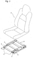
- the slide adjuster includes a pair of slide adjuster units S disposed on respective sides of the seat A for use in adjusting the position of the seat A in the longitudinal direction of a vehicle body.
- each slide adjuster unit S includes a lower rail 2 extending in the longitudinal direction of the vehicle body and rigidly secured to a vehicle floor, and also includes an upper rail 4 mounted on the lower rail 2 so as to be slidable relative thereto.
- a generally rectangular seat mounting frame 6 is joined to the right and left upper rails 4, and the seat A is mounted on the seat mounting frame 6.
- the lower rail 2 has a cross section generally in the form of a figure "U” and is held by a U-shaped channel 8.
- the right and left U-shaped channels 8 are connected to each other by front and rear connecting members 10.
- the upper rail 4 has a cross section generally in the form of an inverted figure of "U"
- the seat mounting frame 6 has front and rear overhangs 6a extending laterally outwardly towards a central portion of the vehicle body.
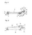
- a seat belt holding plate 12 has a horizontally extending inner side portion 12a, which is joined to an upper surface of one of the right and left upper rails 4 that is positioned on the central side (tunnel side) of the vehicle body.
- the seat belt holding plate 12 also has a first inclined portion 12b extending laterally outwardly and obliquely upwardly from the inner side portion 12a, a horizontally extending medial portion 12c extending laterally outwardly from the first inclined portion 12b, a second inclined portion 12d extending laterally outwardly and obliquely upwardly from the medial portion 12c, and a vertical portion 12e extending upwardly from the second inclined portion 12d.
- the vertical portion 12e has a seat belt anchor 14 formed therewith.
- a planar auxiliary rail 16 is joined to a lower surface of the horizontally extending medial portion 12c of the set belt holding plate 12 so as to extend laterally outwardly.
- a reinforcing plate 18 has a horizontally extending inner side portion 18a, which is joined to a lower surface of one of the U-shaped channels 8 that holds the lower rail 2 positioned on the central side of the vehicle body.
- the reinforcing plate 18 also has an inclined portion 18b extending laterally outwardly and obliquely upwardly from the inner side portion 18a, and a horizontally extending portion 18c extending laterally outwardly from the inclined portion 18b.
- An auxiliary rail guide 20 made of, for example, a resin is mounted on an outer side portion of the reinforcing plate 18, and a guide support 22 is secured to the outer side portion of the reinforcing plate 18 to support the auxiliary rail guide 20.
- the auxiliary rail guide 20 has a guide groove defined therein, in which an outer edge portion of the auxiliary rail 16 is loosely inserted.
- the seat belt holding plate 12 and the reinforcing plate 18 have such a positional relationship that the first inclined portion 12b of the former and the inclined portion 18b of the latter extend parallel to each other, and the horizontally extending medial portion 12c of the former and the horizontally extending portion 18c of the latter extend parallel to each other.
- a belt 24 Opposite ends of a belt 24 are secured to the inclined portion 18b of the reinforcing plate 18 confronting the seat belt holding plate 12, and a belt guide 26 having a guide groove defined therein, in which the belt 24 is loosely inserted, is secured to the first inclined portion 12b of the seat belt holding plate 12 by a bolt 28 and to the horizontally extending medial portion 12c of the seat belt holding plate 12 by a bolt 30.
- a guide support holding member 32 is secured to a portion of the vertical portion 12e of the seat belt holding plate 12 that is positioned laterally outwardly and obliquely upwardly of the belt guide 26. The guide support holding member 32 acts to prevent opening of the guide support 22 to thereby hold the guide support 22 in position.
- front and rear ends of the lower rail 2 that is positioned on the side of a door are secured to the vehicle floor, and front and rear ends of the horizontally extending portion 18c of the reinforcing plate 18 are likewise secured to the vehicle floor, while the automobile seat A is secured to front and rear ends of the seat mounting frame 6 on the side of the door and to the front and rear overhangs 6a.
- the upper rail 4 When the vehicle is running, the upper rail 4 is held on the lower rail 2 at the predetermined position by means of a known locking device. During a stop of the vehicle, if adjustments of the position of the seat are desired, the lock of the upper rail 4 with respect to the lower rail 2 is released by releasing the locking device, and subsequent application of a load to the seat in the longitudinal direction of the vehicle causes the upper rail 4 to slide along the lower rail 2.
- the locking device is operated at a desired position, the upper rail 4 is again locked with respect to the lower rail 2, and the seat is held at such a desired position.
- the auxiliary rail 16 slides along the auxiliary rail guide 20 with the outer edge portion of the auxiliary rail 16 received in the guide groove in the auxiliary rail guide 20.
- a portion (latch release) of a seat belt (not shown) that is retractable into, for example, a pillar of the vehicle body is latched in the seat belt anchor 14, thereby protecting the seat occupant in the event of a collision of the vehicle or the like.
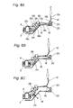
- a load F less than a predetermined value is applied to the seat belt anchor 14 in the direction indicated by an arrow due to, for example, a collision of the vehicle, the strength of the seat belt holding plate 12 withstands the load F and, at the same time, the strength of the reinforcing plate 18 similarly withstands the load F because the auxiliary rail 16 joined to the seat belt holding plate 12 is received in the auxiliary rail guide 20.
- a large load F greater than the predetermined value is applied to the seat belt anchor 14 to thereby gradually deform the auxiliary rail 16, as shown in Fig. 6B, it sometimes occurs that the auxiliary rail 16 is separated from the auxiliary rail guide 20.
- a tension G is applied to the belt 24 inserted in the belt guide 26 to withstand the load F.
- the slide adjuster according to the present invention can effectively increase the strength of separation between the seat belt anchor and the rail with a relatively small space without increasing the thickness of the lower rail or the upper rail, it can be effectively utilized in an automotive vehicle having a reduced space between the floor and the seat such as, for example, a one-box car, a truck and the like.
Landscapes
- Engineering & Computer Science (AREA)
- Mechanical Engineering (AREA)
- Aviation & Aerospace Engineering (AREA)
- Transportation (AREA)
- Seats For Vehicles (AREA)
- Automotive Seat Belt Assembly (AREA)
- Emergency Lowering Means (AREA)
Applications Claiming Priority (1)
| Application Number | Priority Date | Filing Date | Title |
|---|---|---|---|
| JP2005141467A JP4679961B2 (ja) | 2005-05-13 | 2005-05-13 | 車両用シートのスライド装置 |
Publications (2)
| Publication Number | Publication Date |
|---|---|
| EP1721776A2 true EP1721776A2 (de) | 2006-11-15 |
| EP1721776A3 EP1721776A3 (de) | 2010-06-02 |
Family
ID=36821873
Family Applications (1)
| Application Number | Title | Priority Date | Filing Date |
|---|---|---|---|
| EP06009822A Withdrawn EP1721776A3 (de) | 2005-05-13 | 2006-05-12 | Kraftfahrzeug- Gleitschiene |
Country Status (5)
| Country | Link |
|---|---|
| US (1) | US7533932B2 (de) |
| EP (1) | EP1721776A3 (de) |
| JP (1) | JP4679961B2 (de) |
| KR (1) | KR100899906B1 (de) |
| CN (1) | CN100436204C (de) |
Families Citing this family (13)
| Publication number | Priority date | Publication date | Assignee | Title |
|---|---|---|---|---|
| US20070199759A1 (en) * | 2006-02-24 | 2007-08-30 | Dan Tang | Device And Method For Reinforcing A Vehicle Having A Pillared Roof |
| US7854512B2 (en) * | 2007-02-22 | 2010-12-21 | Skyler M Tegland | Apparatus for mounting motion picture camera equipment |
| JP5463659B2 (ja) * | 2008-12-04 | 2014-04-09 | 日産自動車株式会社 | 車両用シートのシートクッション構造 |
| USD680340S1 (en) * | 2012-03-21 | 2013-04-23 | Johnson Controls Gmbh | Seat for vehicles |
| JP5580371B2 (ja) * | 2012-08-10 | 2014-08-27 | 本田技研工業株式会社 | 車両用シート |
| JP6188244B2 (ja) * | 2012-12-27 | 2017-08-30 | テイ・エス テック株式会社 | シート装置 |
| JP6118289B2 (ja) * | 2013-09-24 | 2017-04-19 | 株式会社神戸製鋼所 | 建設機械のオペレータ用シート構造体 |
| DE102015005296A1 (de) * | 2015-04-24 | 2016-10-27 | GM Global Technology Operations LLC (n. d. Ges. d. Staates Delaware) | Kraftfahrzeugsitzanordnung |
| US9821683B2 (en) * | 2015-05-22 | 2017-11-21 | AISIN Technical Center of America, Inc. | Easy seat positioning and installation |
| KR102496370B1 (ko) | 2016-03-07 | 2023-02-06 | 삼성전자주식회사 | 레일장치 및 이를 갖는 냉장고 |
| CN106004567A (zh) * | 2016-06-18 | 2016-10-12 | 金余和 | 扶手缓冲汽车安全座椅 |
| JP6761170B2 (ja) * | 2016-08-03 | 2020-09-23 | テイ・エス テック株式会社 | 乗物用シート |
| JP7436818B2 (ja) * | 2020-03-20 | 2024-02-22 | テイ・エス テック株式会社 | 乗物用シート |
Citations (1)
| Publication number | Priority date | Publication date | Assignee | Title |
|---|---|---|---|---|
| JPH10297327A (ja) | 1997-04-30 | 1998-11-10 | Tachi S Co Ltd | 車両用シートのスライド装置 |
Family Cites Families (16)
| Publication number | Priority date | Publication date | Assignee | Title |
|---|---|---|---|---|
| DE2742668C2 (de) * | 1977-09-22 | 1982-11-18 | Adam Opel AG, 6090 Rüsselsheim | Sicherheitsgurtbefestigung |
| JPS57178954A (en) * | 1981-04-30 | 1982-11-04 | Isuzu Motors Ltd | Guide apparatus of car seat belt |
| JPS58130849U (ja) * | 1982-03-01 | 1983-09-03 | 富士機工株式会社 | シ−トベルト装置の取付構造 |
| JPS6156124U (de) * | 1984-09-18 | 1986-04-15 | ||
| JPS6175362U (de) * | 1984-10-23 | 1986-05-21 | ||
| JPS6218348A (ja) * | 1985-07-17 | 1987-01-27 | Nissan Motor Co Ltd | シ−トスライド装置 |
| AU6276386A (en) * | 1985-09-20 | 1987-06-04 | Toyota Jidosha Kabushiki Kaisha | Belt anchor |
| JPH0439084Y2 (de) * | 1985-12-09 | 1992-09-11 | ||
| JPH0636996Y2 (ja) * | 1988-03-31 | 1994-09-28 | アイシン精機株式会社 | シートスライド装置 |
| JPH02142362U (de) * | 1989-04-28 | 1990-12-03 | ||
| JPH0353330U (de) * | 1989-09-30 | 1991-05-23 | ||
| JPH0360149U (de) * | 1989-10-18 | 1991-06-13 | ||
| JP2596235Y2 (ja) * | 1993-10-13 | 1999-06-07 | 株式会社タチエス | シートスライド装置 |
| KR100200502B1 (ko) | 1996-09-17 | 1999-06-15 | 윤종용 | 제이테그 콘트롤러를 이용한 코아로직 콘트롤 및 관찰장치 |
| KR19980021554U (ko) * | 1996-10-21 | 1998-07-15 | 김영귀 | 차량용 시트의 슬라이딩 장치 |
| EP1323598B1 (de) * | 2001-12-28 | 2005-11-16 | Mitsubishi Jidosha Kogyo Kabushiki Kaisha | Fahrzeugsitz |
-
2005
- 2005-05-13 JP JP2005141467A patent/JP4679961B2/ja not_active Expired - Fee Related
-
2006
- 2006-04-25 KR KR1020060037121A patent/KR100899906B1/ko not_active Expired - Fee Related
- 2006-04-26 US US11/411,103 patent/US7533932B2/en not_active Expired - Fee Related
- 2006-05-12 EP EP06009822A patent/EP1721776A3/de not_active Withdrawn
- 2006-05-12 CN CNB2006100826869A patent/CN100436204C/zh not_active Expired - Fee Related
Patent Citations (1)
| Publication number | Priority date | Publication date | Assignee | Title |
|---|---|---|---|---|
| JPH10297327A (ja) | 1997-04-30 | 1998-11-10 | Tachi S Co Ltd | 車両用シートのスライド装置 |
Also Published As
| Publication number | Publication date |
|---|---|
| JP4679961B2 (ja) | 2011-05-11 |
| CN1861446A (zh) | 2006-11-15 |
| KR20060117193A (ko) | 2006-11-16 |
| EP1721776A3 (de) | 2010-06-02 |
| KR100899906B1 (ko) | 2009-05-28 |
| JP2006315577A (ja) | 2006-11-24 |
| CN100436204C (zh) | 2008-11-26 |
| US20060255582A1 (en) | 2006-11-16 |
| US7533932B2 (en) | 2009-05-19 |
Similar Documents
| Publication | Publication Date | Title |
|---|---|---|
| US10882425B2 (en) | Longitudinal adjuster and vehicle seat | |
| US7533932B2 (en) | Slide adjuster for an automobile seat | |
| US10919415B2 (en) | Longitudinal adjuster and vehicle seat | |
| CN103038093B (zh) | 交通工具用座椅构造 | |
| US20070108817A1 (en) | Thigh extension system for a vehicle seat | |
| KR20070090753A (ko) | 화물용 보유장치 | |
| US7731461B2 (en) | Load-bearing rail | |
| EP1980458A2 (de) | Gurtführungsverankerung und Gurtführungseinheit damit | |
| US11414045B2 (en) | Anchor position adjustment device | |
| US6869105B2 (en) | Four-point seat restraint | |
| EP0450914A1 (de) | Sperrvorrichtung für Sicherheitsgurtstrammer | |
| US9010831B2 (en) | Motor vehicle with an adjustable loading panel in a cargo space | |
| US9358948B2 (en) | Buckle device for seat belt of vehicle | |
| US20040262973A1 (en) | System for locking a first element with a second element, and a seat with such a locking system | |
| US9499086B2 (en) | Motor vehicle with an adjustable loading panel in a cargo space | |
| JP2009292367A (ja) | 2ドア車のセンターピラー構造 | |
| US8113566B2 (en) | Loading space cover | |
| EP4005867A1 (de) | Sitzgleitversteller | |
| US10377339B2 (en) | Seatbelt tensioning assembly | |
| EP4005868B1 (de) | Sitzgleitvorrichtung und verbindungsstruktur des gleithebels in der sitzgleitvorrichtung | |
| US20050285005A1 (en) | Automotive seat track having vertically adjustable bearings | |
| KR100410722B1 (ko) | 자동차용 시트 슬라이드 트랙 | |
| KR200196806Y1 (ko) | 시트 슬라이더 안전 후크 | |
| KR101972332B1 (ko) | 시트 레일의 록킹 장치용 보강 구조 | |
| JP2008100625A (ja) | シートベルトのアンカー構造 |
Legal Events
| Date | Code | Title | Description |
|---|---|---|---|
| PUAI | Public reference made under article 153(3) epc to a published international application that has entered the european phase |
Free format text: ORIGINAL CODE: 0009012 |
|
| AK | Designated contracting states |
Kind code of ref document: A2 Designated state(s): AT BE BG CH CY CZ DE DK EE ES FI FR GB GR HU IE IS IT LI LT LU LV MC NL PL PT RO SE SI SK TR |
|
| AX | Request for extension of the european patent |
Extension state: AL BA HR MK YU |
|
| PUAL | Search report despatched |
Free format text: ORIGINAL CODE: 0009013 |
|
| AK | Designated contracting states |
Kind code of ref document: A3 Designated state(s): AT BE BG CH CY CZ DE DK EE ES FI FR GB GR HU IE IS IT LI LT LU LV MC NL PL PT RO SE SI SK TR |
|
| AX | Request for extension of the european patent |
Extension state: AL BA HR MK YU |
|
| 17P | Request for examination filed |
Effective date: 20101202 |
|
| AKX | Designation fees paid |
Designated state(s): DE FR GB IT |
|
| GRAP | Despatch of communication of intention to grant a patent |
Free format text: ORIGINAL CODE: EPIDOSNIGR1 |
|
| RIC1 | Information provided on ipc code assigned before grant |
Ipc: B60R 22/26 20060101ALI20110530BHEP Ipc: B60N 2/07 20060101AFI20110530BHEP |
|
| STAA | Information on the status of an ep patent application or granted ep patent |
Free format text: STATUS: THE APPLICATION IS DEEMED TO BE WITHDRAWN |
|
| 18D | Application deemed to be withdrawn |
Effective date: 20111109 |