EP1722437B1 - Vorrichtung zum Eintaschen von Batterieplatten - Google Patents
Vorrichtung zum Eintaschen von Batterieplatten Download PDFInfo
- Publication number
- EP1722437B1 EP1722437B1 EP06252258A EP06252258A EP1722437B1 EP 1722437 B1 EP1722437 B1 EP 1722437B1 EP 06252258 A EP06252258 A EP 06252258A EP 06252258 A EP06252258 A EP 06252258A EP 1722437 B1 EP1722437 B1 EP 1722437B1
- Authority
- EP
- European Patent Office
- Prior art keywords
- enveloper
- crease
- plate
- control
- anvil
- Prior art date
- Legal status (The legal status is an assumption and is not a legal conclusion. Google has not performed a legal analysis and makes no representation as to the accuracy of the status listed.)
- Expired - Lifetime
Links
Images


Classifications
-
- B—PERFORMING OPERATIONS; TRANSPORTING
- B65—CONVEYING; PACKING; STORING; HANDLING THIN OR FILAMENTARY MATERIAL
- B65B—MACHINES, APPARATUS OR DEVICES FOR, OR METHODS OF, PACKAGING ARTICLES OR MATERIALS; UNPACKING
- B65B51/00—Devices for, or methods of, sealing or securing package folds or closures; Devices for gathering or twisting wrappers, or necks of bags
- B65B51/10—Applying or generating heat or pressure or combinations thereof
-
- H—ELECTRICITY
- H01—ELECTRIC ELEMENTS
- H01M—PROCESSES OR MEANS, e.g. BATTERIES, FOR THE DIRECT CONVERSION OF CHEMICAL ENERGY INTO ELECTRICAL ENERGY
- H01M10/00—Secondary cells; Manufacture thereof
- H01M10/04—Construction or manufacture in general
- H01M10/0404—Machines for assembling batteries
-
- B—PERFORMING OPERATIONS; TRANSPORTING
- B65—CONVEYING; PACKING; STORING; HANDLING THIN OR FILAMENTARY MATERIAL
- B65B—MACHINES, APPARATUS OR DEVICES FOR, OR METHODS OF, PACKAGING ARTICLES OR MATERIALS; UNPACKING
- B65B51/00—Devices for, or methods of, sealing or securing package folds or closures; Devices for gathering or twisting wrappers, or necks of bags
- B65B51/10—Applying or generating heat or pressure or combinations thereof
- B65B51/22—Applying or generating heat or pressure or combinations thereof by friction or ultrasonic or high-frequency electrical means
-
- H—ELECTRICITY
- H01—ELECTRIC ELEMENTS
- H01M—PROCESSES OR MEANS, e.g. BATTERIES, FOR THE DIRECT CONVERSION OF CHEMICAL ENERGY INTO ELECTRICAL ENERGY
- H01M10/00—Secondary cells; Manufacture thereof
- H01M10/06—Lead-acid accumulators
- H01M10/12—Construction or manufacture
- H01M10/14—Assembling a group of electrodes or separators
-
- Y—GENERAL TAGGING OF NEW TECHNOLOGICAL DEVELOPMENTS; GENERAL TAGGING OF CROSS-SECTIONAL TECHNOLOGIES SPANNING OVER SEVERAL SECTIONS OF THE IPC; TECHNICAL SUBJECTS COVERED BY FORMER USPC CROSS-REFERENCE ART COLLECTIONS [XRACs] AND DIGESTS
- Y02—TECHNOLOGIES OR APPLICATIONS FOR MITIGATION OR ADAPTATION AGAINST CLIMATE CHANGE
- Y02E—REDUCTION OF GREENHOUSE GAS [GHG] EMISSIONS, RELATED TO ENERGY GENERATION, TRANSMISSION OR DISTRIBUTION
- Y02E60/00—Enabling technologies; Technologies with a potential or indirect contribution to GHG emissions mitigation
- Y02E60/10—Energy storage using batteries
-
- Y—GENERAL TAGGING OF NEW TECHNOLOGICAL DEVELOPMENTS; GENERAL TAGGING OF CROSS-SECTIONAL TECHNOLOGIES SPANNING OVER SEVERAL SECTIONS OF THE IPC; TECHNICAL SUBJECTS COVERED BY FORMER USPC CROSS-REFERENCE ART COLLECTIONS [XRACs] AND DIGESTS
- Y02—TECHNOLOGIES OR APPLICATIONS FOR MITIGATION OR ADAPTATION AGAINST CLIMATE CHANGE
- Y02P—CLIMATE CHANGE MITIGATION TECHNOLOGIES IN THE PRODUCTION OR PROCESSING OF GOODS
- Y02P70/00—Climate change mitigation technologies in the production process for final industrial or consumer products
- Y02P70/50—Manufacturing or production processes characterised by the final manufactured product
Definitions
- This invention relates to envelopers for creating a material envelope around a battery plate and apparatus for forming groups of battery plates.
- the invention consists in an enveloper for creating a material envelope around a battery plate, including an anvil and a rotatable cut-and-crease roller having a knife and a generally diametrically opposed crease blade for acting against the anvil to cut-and-crease material fed through the enveloper characterised in that the enveloper further includes a control for varying the rotational velocity of the roller during a rotational cycle to position the crease to form a symmetrical envelope around a plate passing through the enveloper.
- the cut-and-crease roller is driven by a servomotor, in which case the control may include an input for adjusting the rotational velocity to compensate for a "long on top” condition and/or a "short on top” condition.
- long on top is the condition when, when viewed from above, the envelope material covering the upper surface of an envelope plate extends beyond the top edge of the body of the plate and at least partially covers the plate terminal.
- short on top is the condition when viewed from above the material of an envelope plate leaves some of the main body of the plate exposed. The desired condition is for the material to sit symmetrically about the plate and to terminate, on each side, level with the upper edge of the main body of the plate.
- the apparatus may include a recognition unit for determining the presence of a "long on top” or “short on top” condition and for feeding a respective control signal to the control.
- a recognition unit for determining the presence of a "long on top” or “short on top” condition and for feeding a respective control signal to the control.
- the apparatus adjusted in substantially real time, whilst running, but the more normal operation will be for a few test plates to be fed through the enveloper and then examined by the operator or recognition unit. Depending on the condition detected the rotational velocity will be adjusted as indicated above.
- control includes a memory for retaining a velocity profile for a particular plate/material combination, because in that case, when the operator wishes to run the machine at a future time using that plate and material combination, it can be automatically reset the stored parameters.
- the enveloper for creating material envelope around a battery plate may include a pair of feed rollers for feeding the material into a enveloping station of the enveloper, one of the feed rollers being driven by a motor characterised in that the motor is a servomotor and in that the enveloper further includes a control for controlling the rate of rotation of the feed roller to adjust the length of material formed into an envelope by the enveloping station.
- the control may have a memory for retaining the rotational speeds for any material/plate combination. As indicated before this will assist with resetting.
- the anvil may be displacably mounted to allow adjustment of a gap between the anvil and the cut-and-crease roller to vary the depth of crease formed in material fed through the gap.
- This embodiment is concerned with a problem relating to the depth of crease. It if is too deep, the material is cut through; if it is too shallow a proper and accurate crease is not made. Attempts have been made to overcome this problem by spring-loading the blade, but these have been unsuccessful. Currently, therefore a skilled operator has to adjust the crease blade position using trial and error. This is particularly difficult, because the crease blade must be maintained parallel with the surface of the roller, or else the crease depth will not be consistent across the envelope. The Applicants approach of adjusting the gap between the anvil and the crease roller is a significant departure from the prior art approaches.
- the anvil is pivotally mounted about an axis at a position off-set from the gap.
- the invention may include a rotatable eccentric located on the opposite side of the gap from the axis to displace the anvil by rotation about the axis. This means that the adjustment of the anvil can be both controlled and repeatable.
- Spring means are preferably provided for urging the anvil against the eccentric and this eccentric is conveniently rotated by a servomotor.
- the enveloper may include a control for adjusting the anvil position and hence the gap width to achieve a desired crease depth.
- Control may include a memory for retaining the anvil positions appropriate for any particular material or material plate combination.
- the enveloper may further include a tension roller for tensioning the material prior to cutting and located downstream of the cut-and-crease roller, but upstream of the envelope forming station.
- the tension roller may be driven by a servomotor and the servomotor may be controlled by a control having a memory for retaining the appropriate tension setting for a particular material. It is preferred, however, that the tension roller is driven by a drive for the feed rollers, but with a slight geared step up.
- the invention consists in apparatus for forming groups of battery plates including a first plate supply for supplying spaced plates, an enveloper as defined above for enveloping in material the plates from the first supply, a second plate supply for supplying unenveloped plates to form stacks of an enveloped plate and an unenveloped plate, a conveyor for conveying the stacks to an outlet and a pocket conveyor for receiving multiple stacks from the outlet for forming groups characterised in that at least a plurality of the above elements has at least one adjustable feature controlled by a respective servomotor to allow for different plate/envelope material combinations and a control for adjusting the servomotors.
- the control may include a memory for retaining the control settings for each plate/envelope combination used in the apparatus to allow automatic resetting of the apparatus.
- the apparatus may include plate guides, on one or more conveyor, which can be adjusted to accommodate plates of different sizes; adjustable pockets on the pocket conveyor to accommodate groups of different sizes and/or an interrupt device for temporarily retaining one or more stacks of plates, before they are fed into the pocket conveyor. Any such settings can be stored and re-set.
- the apparatus for forming groups is generally indicated at 10 and includes upstream plate supplies 11, 11', envelopers 12, 12', first downstream plate supplies, 13, 13' and an auxiliary plate supply 14.
- Plate supplies 11, 11' and 13, 13' deliver plates onto respective main conveyors, 15, 15'.
- Auxiliary plate supply 14, which is more occasionally used, can supply plates onto both conveyors 15, 15'. Plates supplied onto the main conveyors 15, 15' are enveloped at 12, 12' by material taken from reels 21. For many batteries, alternate enveloped and unenveloped plates are required and so the supplies 13, 13' insert an unenveloped plate either between each enveloped plate, or, more conveniently, onto an enveloped plate to form a mini stack.
- the supply 14 can be used to introduce plates so that they will lie either on top of the unenveloped plate on the stack of effectively lie below the enveloped plate. If a pair of enveloped plates are required immediately adjacent to each other, then the supply 13 is momentarily stopped. Conveyors 15, 15' feed stackers 16, 16' which then enter the buffer 17. Apparatus 18 picks up the groups formed by the stackers 16, 16' alternatively and in this way supply groups to the cast-on strap feed 19, where the groups move forward to a cast-on strap machine (not shown).
- each conveyor 24, 24' has guides 26. As is explained below, these may be adjustable. Similar guides exist elsewhere in the apparatus 10.
- FIG. 3 illustrates an enveloper 12, 12' and briefly consists of feed rollers 27 cooperative cut-and-crease roller 28 and anvil 29, a control driven roller 30 and a cooperating idler roller 31, a pair of sealing wheels 32, which include tooth formations for crimping the edges of the envelope in a manner known in the art, and a reciprocating shuttle for feeding the plate off the conveyor 15 towards the sealing rollers 32.
- the passage of material 34, from the reels 21, through the enveloper 12, 12' is indicated.
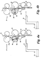
- the enveloper 12 operates in a conventional manner with the feed rollers 27 feeding the material 34 into the nip between the cut-and-crease roller 28 and the anvil 29, the cut-and-crease roller 28 has a knife 35 and a crease blade 36, which is set into the roller at diametrically opposed positions. This position is shown in Figure 4a . As the cut-and-crease roller 28 rotates, the crease blade 36 forms a crease in the material, by acting against the anvil 29, as it passes through the nip between the roller 28 and the anvil 29. This position is shown in Figure 4b .
- the crease material continues to be fed downwardly past the guides 39, 40, which define a horizontal slot 41 (see Figure 4c ).
- the knife 35 cuts the material against the anvil 29 and the cut material continues to descend past the slot 41 until the crease 42 is aligned with the slot 41.
- the shuttle 33 has begun to advance towards the slot 41 and as the crease 42 becomes aligned with the slot 41 the leading edge 43 of the shuttle 33 engages in the crease 42 to begin to push the crease into the slot 41.
- a plate 44 is delivered onto the shuttle by conveyor 15 (see Figure 4d ).
- the shuttle 33 carries the plate 44 and the cut piece of material 45 through the slot 41 causing the material 45 to fold around the plate 44 and delivering the material and plate into the nip 47 of two sealing rollers 48 that remove the plate 44 and material 45 from the now retracting shuttle 33 (see Figure 4f ) to deliver the fully enveloped plate 44a as shown in Figure 4g .
- the edges of the cut material 45 are crimped together using toothed wheels in a manner known to those skilled in the art.
- Such a driving arrangement could be achieved in a number of ways, but it is particularly convenient to use a servomotor, which can be computer controlled. In this way an operator can adjust the computer control, which will be described in more detail below, to achieve symmetrically enveloped plates. In doing so he records the plate size and material being processed and this setting will be retained by the computer control to allow automatic resetting whenever the operator wants to run that combination through the apparatus again.
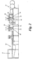
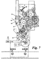
- Figures 5 to 7 The possibility for adjusting the crease depth is best illustrated in Figures 5 to 7 , which view the enveloper 12 from the opposite side to the views shown in Figures 3 and 4 .
- Figure 7 is a view of the complete operational layout, but the arrangement can most simply be seen in Figures 5 and 6 .
- the anvil 29 is mounted on a carrier plate 49, which is itself pivotally mounted at 50.
- Rocking of the carrier plate about the pivot 50 can vary the width of the gap or nip 51 which exists between the anvil 29 and the cut-and-crease roller 28.
- the width of the gap 51 determines the depth of the crease formed in the material for a fixed position of the crease blade 36.
- the carrier plate 49 On the opposite side of the gap 51, from the pivot 50, the carrier plate 49 has a cam following plate 52 which is located to engage a rotatable eccentric 53. (As can be seen in Figure 7 a spring 54 is provided to urge the plate 52 against the eccentric 53).
- a spring 54 is provided to urge the plate 52 against the eccentric 53.
- the gap 51 can vary between 2.3 mm and 0 mm depending on the rotational position of the eccentric 53.
- Figure 6 illustrates the drive for the eccentric 53 which comprises a servomotor 54 and gear chain 55.
- the anvil position can therefore be adjusted by the servomotor 54 and the appropriate anvil position for any particular plate/material combination can be stored. This adjustment of the anvil position needs to be compensated for in connection with the knife 35. Spring loading the knife 35 is sufficient in most cases.
- roller 30 is driven through the feed roller 27a through a slightly stepped up gear chain.
- a servomotor may be used. Either way the rate of rotation of the roller 30 can be precisely controlled and maybe varied depending on whether it is being used to tension the material 34 or feed the material 45. Again the settings for the servomotor can be adjusted on setup and stored for subsequent automatic setup.
- the applicants have determined that in fact in may be advantageous to remove the vertical plates which define the nip 41. This is because the crease can sometimes be misplaced by differential friction arising between the material 45 and the respective plates. In fact, the formation of the crease tends to be enhanced, because the material gets deflected against the rollers 32, helping formation of the crease.
- Figure 8 is a controlled diagram for the apparatus 10. It will be noted that servomotors are used throughout the apparatus both as described above, and also to control the speed of the various conveyors and also, at, 55 a servomotor 56 is provided for adjusting the spacing of the pockets on the pocket conveyor 16. Further servomotors are provided to adjust guides 22 and 58. The servomotors are all controlled by a servodrive control system 57 which in turn can be operator controlled through an interface 58. This use of servomotors and controls also enables precise relative adjustments between the operating speeds of the various parts of the apparatus.
- the Applicants have envisaged the apparatus as a single entity with a large number of controllable adjustable features, rather than considering each element of the apparatus as being a completely independent device, which requires individual setting up by a skilled operator each time the plate/material combination is changed. Not only have the Applicants achieved a way of allowing a machine to be automatically set up, once a "recipe" has been determined for any particular plate material combination they have also created apparatus which could be, at least in part, dynamically controlled, in real time, to self adjust to allow for manufacturing variations in the plates or material.
Landscapes
- Engineering & Computer Science (AREA)
- Manufacturing & Machinery (AREA)
- Chemical & Material Sciences (AREA)
- Chemical Kinetics & Catalysis (AREA)
- Electrochemistry (AREA)
- General Chemical & Material Sciences (AREA)
- Mechanical Engineering (AREA)
- Making Paper Articles (AREA)
- Sealing Battery Cases Or Jackets (AREA)
- Packaging Of Special Articles (AREA)
- Battery Mounting, Suspending (AREA)
- Cell Separators (AREA)
- Auxiliary Devices For And Details Of Packaging Control (AREA)
- Secondary Cells (AREA)
- Supplying Of Containers To The Packaging Station (AREA)
- Perforating, Stamping-Out Or Severing By Means Other Than Cutting (AREA)
- Fish Paste Products (AREA)
- Primary Cells (AREA)
Claims (20)
- Umhüllungseinrichtung (10) zur Erzeugung einer Materialumhüllung um eine Batterieplatte, mit einem Amboss (29) und einer drehbaren Schneid- und Rillwalze (28) mit einem Messer (35) und einer insgesamt diametral gegenüberliegenden Rillklinge (36) für eine Wirkung gegen den Amboss (28), um ein durch die Umhüllungseinrichtung (10) geführtes Material zu schneiden und zu rillen, dadurch gekennzeichnet, dass die Umhüllungseinrichtung (10) außerdem eine Steuerung (57) zur Veränderung der Drehgeschwindigkeit der Walze (28) während eines Drehzyklus aufweist, um die Rille so zu positionieren, dass eine symmetrische Umhüllung um eine Platte gebildet wird, die die Umhüllungseinrichtung (10) durchläuft.
- Umhüllungseinrichtung (10) nach Anspruch 1, bei der die Schneid- und Rillwalze (28) von einem Servomotor angetrieben wird.
- Umhüllungseinrichtung (10) nach Anspruch 1 oder 2, bei der die Steuerung (57) einen Eingang für eine Einstellung der Drehgeschwindigkeit zur Kompensierung eines "Oben-lang"-Zustands aufweist.
- Umhüllungseinrichtung (10) nach einem der vorhergehenden Ansprüche, bei der die Steuerung (57) einen Eingang für eine Einstellung der Drehgeschwindigkeit zur Kompensierung eines "Oben-kurz"-Zustands aufweist.
- Umhüllungseinrichtung (10) nach einem der vorhergehenden Ansprüche, die eine Erkennungseinheit für eine Bestimmung des Vorhandenseins eines "Obenlang"- oder "Oben-kurz"-Zustands und für eine Zufuhr eines jeweiligen Steuersignals an die Steuerung aufweist.
- Umhüllungseinrichtung (10) nach einem der vorhergehenden Ansprüche, bei der die Steuerung (57) einen Speicher für eine Aufbewahrung eines Geschwindigkeitsprofils für eine bestimmte Platten-/Materialkombination aufweist.
- Umhüllungseinrichtung nach Anspruch 1, mit einem Paar von Zuführwalzen (27) für eine Zufuhr des Materials zu dem Amboss (29) und der Schneid- und Rillwalze (28), wobei eine der Zufuhrwalzen (27a) von einem Servomotor angetrieben wird und die Umhüllungseinrichtung außerdem eine Steuerung (57) zur Steuerung der Drehzahl der Zuführrolle (27a) aufweist, um die Länge des Materials einzustellen, das durch die Umhüllungsstation zu einer Umhüllung geformt wird.
- Umhüllungseinrichtung nach Anspruch 7, bei der die Steuerung (57) einen Speicher zur Aufbewahrung der für jegliche Material-/Plattenkombination geeigneten Drehzahl aufweist.
- Umhüllungseinrichtung nach einem der vorhergehenden Ansprüche, bei der der Amboss (24) verschiebbar angebracht ist, um eine Einstellung einer Lücke (51) zwischen dem Amboss (29) und der Schneid- und Rillrolle (28) zu ermöglichen, um die Tiefe der Rille einzustellen, die in dem Material ausgebildet wird, das durch die Lücke geführt wird.
- Umhüllungseinrichtung nach Anspruch 9, bei der der Amboss (29) an einer zu der Lücke (51) versetzten Position um eine Achse schwenkbar angebracht ist.
- Umhüllungseinrichtung nach Anspruch 10, die außerdem einen drehbaren Exzenter (53) aufweist, der von der Achse aus auf der entgegen gesetzten Seite der Lücke angeordnet ist, um den Amboss (29) durch Drehung um die Achse zu verschieben.
- Umhüllungseinrichtung nach Anspruch 11, die außerdem eine Federeinrichtung (54) aufweist, die den Amboss (29) gegen den Exzenter (53) drückt.
- Umhüllungseinrichtung nach Anspruch 11 oder Anspruch 12, bei der der Exzenter durch einen Servomotor (54a) gedreht wird.
- Umhüllungseinrichtung nach einem der Ansprüche 9 bis 13, die außerdem eine Steuerung (57) für eine Einstellung der Ambossposition und daher der Lückenbreite aufweist, um eine gewünschte Rilltiefe zu erreichen.
- Umhüllungseinrichtung nach Anspruch 14, bei der die Steuerung einen Speicher zur Aufbewahrung der Ambosspositionen aufweist, die für bestimmte Materialien oder Material-/Plattenkombinationen geeignet sind.
- Umhüllungseinrichtung nach einem der vorhergehenden Ansprüche, bei der die Umhüllungseinrichtung ein Paar von Zuführwalzen und eine Umhüllungsformstation aufweist und außerdem eine Zugwalze (30) aufweist, die das Material vor dem Schneiden spannt und die stromabwärts der Schneid- und Rillstation, jedoch stromaufwärts der Umhüllungsformstation angeordnet ist.
- Umhüllungseinrichtung nach Anspruch 16, bei der die Zugwalze von einem Servomotor oder über eine Zuführwalze angetrieben wird.
- Umhüllungseinrichtung nach Anspruch 16, bei der der Servomotor durch eine Steuerung gesteuert wird, die einen Speicher für eine Aufbewahrung der geeigneten Spannungseinstellung für ein bestimmtes Material aufweist.
- Vorrichtung zur Bildung von Gruppen von Batterieplatten, mit einer ersten Plattenzufuhreinrichtung, die aufeinanderfolgend im Abstand angeordnete Platten (12) zuführt, einer Umhüllungseinrichtung nach einem der vorhergehenden Ansprüche zur Materialumhüllung der Platten von der ersten Zufuhreinrichtung (11), einer zweiten Plattenzufuhreinrichtung (13) für eine Zufuhr nicht-umhüllter Platten, um Stapel aus einer umhüllten Platte und einer nicht-umhüllten Platte zu bilden, einer Fördereinrichtung (15) zur Förderung der Stapel zu einem Auslass (16) und einem Taschenförderer zur Aufnahme mehrerer Stapel von dem Auslass zur Bildung von Gruppen, dadurch gekennzeichnet, dass wenigstens eine Vielzahl der oben erwähnten Elemente wenigstens ein einstellbares Merkmal, das durch einen jeweiligen Servomotor gesteuert wird, um unterschiedliche Plattenumhüllungsmaterialkombinationen zu ermöglichen, und eine Steuerung (57) für eine Einstellung der Servomotoren aufweist.
- Vorrichtung nach Anspruch 19, bei der die Steuerung (57) einen Speicher für eine Aufbewahrung der Steuereinstellungen für jede Platten-/Umhüllungskombination aufweist, die in der Vorrichtung verwendet wird, um eine automatische Wiedereinstellung der Vorrichtung zu ermöglichen.
Priority Applications (4)
| Application Number | Priority Date | Filing Date | Title |
|---|---|---|---|
| PL06252258T PL1722437T3 (pl) | 2005-05-12 | 2006-04-27 | Urządzenie do owijania dla płyt akumulatorowych |
| EP08000453A EP1939969B1 (de) | 2005-05-12 | 2006-04-27 | Kuvertiergerät für eine Batterieplatte |
| EP08000452A EP1923947B1 (de) | 2005-05-12 | 2006-04-27 | Vorrichtung zum Eintaschen von Batterieplatten |
| DK08000452.6T DK1923947T3 (da) | 2005-05-12 | 2006-04-27 | Indretning til omvikling af batteriplader |
Applications Claiming Priority (1)
| Application Number | Priority Date | Filing Date | Title |
|---|---|---|---|
| GBGB0509645.8A GB0509645D0 (en) | 2005-05-12 | 2005-05-12 | An enveloper |
Related Child Applications (2)
| Application Number | Title | Priority Date | Filing Date |
|---|---|---|---|
| EP08000453A Division EP1939969B1 (de) | 2005-05-12 | 2006-04-27 | Kuvertiergerät für eine Batterieplatte |
| EP08000452A Division EP1923947B1 (de) | 2005-05-12 | 2006-04-27 | Vorrichtung zum Eintaschen von Batterieplatten |
Publications (3)
| Publication Number | Publication Date |
|---|---|
| EP1722437A2 EP1722437A2 (de) | 2006-11-15 |
| EP1722437A3 EP1722437A3 (de) | 2006-12-20 |
| EP1722437B1 true EP1722437B1 (de) | 2008-10-08 |
Family
ID=34685463
Family Applications (3)
| Application Number | Title | Priority Date | Filing Date |
|---|---|---|---|
| EP08000453A Expired - Lifetime EP1939969B1 (de) | 2005-05-12 | 2006-04-27 | Kuvertiergerät für eine Batterieplatte |
| EP08000452A Expired - Lifetime EP1923947B1 (de) | 2005-05-12 | 2006-04-27 | Vorrichtung zum Eintaschen von Batterieplatten |
| EP06252258A Expired - Lifetime EP1722437B1 (de) | 2005-05-12 | 2006-04-27 | Vorrichtung zum Eintaschen von Batterieplatten |
Family Applications Before (2)
| Application Number | Title | Priority Date | Filing Date |
|---|---|---|---|
| EP08000453A Expired - Lifetime EP1939969B1 (de) | 2005-05-12 | 2006-04-27 | Kuvertiergerät für eine Batterieplatte |
| EP08000452A Expired - Lifetime EP1923947B1 (de) | 2005-05-12 | 2006-04-27 | Vorrichtung zum Eintaschen von Batterieplatten |
Country Status (15)
| Country | Link |
|---|---|
| US (1) | US20060254209A1 (de) |
| EP (3) | EP1939969B1 (de) |
| JP (1) | JP2006318915A (de) |
| KR (1) | KR20060117255A (de) |
| CN (3) | CN101697374B (de) |
| AT (3) | ATE410797T1 (de) |
| BR (1) | BRPI0601663A (de) |
| CA (1) | CA2546751A1 (de) |
| DE (3) | DE602006011929D1 (de) |
| DK (3) | DK1923947T3 (de) |
| ES (3) | ES2314843T3 (de) |
| GB (1) | GB0509645D0 (de) |
| PL (1) | PL1722437T3 (de) |
| PT (1) | PT1722437E (de) |
| TW (3) | TWI337967B (de) |
Families Citing this family (13)
| Publication number | Priority date | Publication date | Assignee | Title |
|---|---|---|---|---|
| ITTO20040826A1 (it) * | 2004-11-23 | 2005-02-23 | Petratto Srl | Macchina cordonatrice-piegatrice per la realizzazione di articoli cartotecnici e di legatoria |
| CN201340884Y (zh) | 2008-11-28 | 2009-11-04 | 深圳市吉阳自动化科技有限公司 | 一种动力电池电芯的全自动制极片袋设备 |
| CN102244230B (zh) * | 2011-06-01 | 2015-05-27 | 胡继宁 | 一种蓄电池极片自动包片机 |
| CN102938474B (zh) * | 2012-11-21 | 2015-04-15 | 上海润腾电子科技有限公司 | 一种蓄电池极板的并联包片机构 |
| KR101605665B1 (ko) * | 2012-12-05 | 2016-03-22 | 닛산 지도우샤 가부시키가이샤 | 전기 디바이스의 세퍼레이터 반송 장치 및 그 반송 방법 |
| CN103236559B (zh) * | 2013-05-16 | 2015-05-13 | 东莞市雅康精密机械有限公司 | 制片卷绕控制系统 |
| TWI495177B (zh) * | 2013-11-06 | 2015-08-01 | Qoros Automotive Co Ltd | 電池組的間隔調整系統和方法 |
| CN106532140B (zh) * | 2016-12-23 | 2023-09-26 | 池州市金能供热有限公司 | 极群封装工序中的极片加工装置 |
| CN108313402A (zh) * | 2018-02-07 | 2018-07-24 | 山东卡林自动化科技有限公司 | 一种热合机构及缓冲气垫机 |
| JP7102379B2 (ja) * | 2019-09-17 | 2022-07-19 | 株式会社東芝 | 袋詰電極の製造装置、集積装置および袋詰電極の製造方法 |
| CN111644703B (zh) * | 2020-06-02 | 2021-05-04 | 浙江兜兰智能设备股份有限公司 | 蓄电池极板分切多工位全自动生产系统及其生产工艺 |
| KR20220011029A (ko) * | 2020-07-20 | 2022-01-27 | 주식회사 엘지에너지솔루션 | 단위 셀 제조 장치 및 방법 |
| CN116253024B (zh) * | 2022-10-08 | 2025-08-01 | 深圳精达宇科技有限公司 | 一种遥控器包装装置 |
Family Cites Families (13)
| Publication number | Priority date | Publication date | Assignee | Title |
|---|---|---|---|---|
| US4314403A (en) * | 1977-06-09 | 1982-02-09 | Yuasa Battery Company Limited | Machine for automatically stacking plate groups for storage batteries |
| US5113489A (en) * | 1989-01-27 | 1992-05-12 | International Business Machines Corporation | Online performance monitoring and fault diagnosis technique for direct current motors as used in printer mechanisms |
| AT392371B (de) * | 1989-05-10 | 1991-03-25 | Elbak Batteriewerke Gmbh | Vorrichtung zum eintaschen und abstapeln von positiven oder negativen platten fuer akkumulatoren |
| AU8196291A (en) * | 1990-07-23 | 1992-02-18 | Tbs Engineering Limited | Enveloping apparatus |
| US5094708A (en) * | 1990-08-28 | 1992-03-10 | Graphic Communications, Inc. | Registration system for a continuous web |
| US5241884A (en) * | 1991-10-11 | 1993-09-07 | F. L. Smithe Machine Company, Inc. | Apparatus for changing the length of envelope blanks cut from a continuous web |
| US6047430A (en) * | 1997-09-30 | 2000-04-11 | Gelco International L.L.C. | Battery plate feeding and handling apparatus |
| JP3098500B2 (ja) * | 1998-11-13 | 2000-10-16 | 日本電気株式会社 | 自動給紙装置 |
| US6585846B1 (en) * | 2000-11-22 | 2003-07-01 | 3M Innovative Properties Company | Rotary converting apparatus and method for laminated products and packaging |
| US6547229B1 (en) * | 2000-11-22 | 2003-04-15 | 3M Innovative Properties Company | Stacking apparatus and method for laminated products and packaging |
| US6497566B2 (en) * | 2000-12-27 | 2002-12-24 | Ford Global Technologies, Inc. | Robotic systems for automated preform processing |
| US20030092551A1 (en) * | 2001-11-14 | 2003-05-15 | Roland Boss | Methods and apparatus for scoring and trimming imaged sheet media |
| TWI260810B (en) | 2004-02-04 | 2006-08-21 | Tbs Eng Ltd | Apparatus for forming groups of battery plates |
-
2005
- 2005-05-12 GB GBGB0509645.8A patent/GB0509645D0/en not_active Ceased
-
2006
- 2006-04-20 TW TW095114197A patent/TWI337967B/zh not_active IP Right Cessation
- 2006-04-20 TW TW098145864A patent/TWI343887B/zh not_active IP Right Cessation
- 2006-04-20 TW TW098145869A patent/TWI371397B/zh not_active IP Right Cessation
- 2006-04-27 DK DK08000452.6T patent/DK1923947T3/da active
- 2006-04-27 DK DK06252258T patent/DK1722437T3/da active
- 2006-04-27 ES ES06252258T patent/ES2314843T3/es not_active Expired - Lifetime
- 2006-04-27 AT AT06252258T patent/ATE410797T1/de not_active IP Right Cessation
- 2006-04-27 ES ES08000452T patent/ES2355372T3/es not_active Expired - Lifetime
- 2006-04-27 AT AT08000453T patent/ATE456164T1/de active
- 2006-04-27 DE DE602006011929T patent/DE602006011929D1/de not_active Expired - Lifetime
- 2006-04-27 EP EP08000453A patent/EP1939969B1/de not_active Expired - Lifetime
- 2006-04-27 PL PL06252258T patent/PL1722437T3/pl unknown
- 2006-04-27 DK DK08000453.4T patent/DK1939969T3/da active
- 2006-04-27 PT PT06252258T patent/PT1722437E/pt unknown
- 2006-04-27 EP EP08000452A patent/EP1923947B1/de not_active Expired - Lifetime
- 2006-04-27 AT AT08000452T patent/ATE493772T1/de active
- 2006-04-27 EP EP06252258A patent/EP1722437B1/de not_active Expired - Lifetime
- 2006-04-27 DE DE602006003013T patent/DE602006003013D1/de not_active Expired - Lifetime
- 2006-04-27 DE DE602006019278T patent/DE602006019278D1/de not_active Expired - Lifetime
- 2006-04-27 ES ES08000453T patent/ES2336385T3/es not_active Expired - Lifetime
- 2006-05-11 CN CN2009102076818A patent/CN101697374B/zh not_active Expired - Fee Related
- 2006-05-11 JP JP2006132781A patent/JP2006318915A/ja active Pending
- 2006-05-11 CN CN2006100817713A patent/CN1866588B/zh not_active Expired - Fee Related
- 2006-05-11 BR BRPI0601663-4A patent/BRPI0601663A/pt not_active IP Right Cessation
- 2006-05-11 CN CN2009102076822A patent/CN101697375B/zh not_active Expired - Fee Related
- 2006-05-12 KR KR1020060042775A patent/KR20060117255A/ko not_active Ceased
- 2006-05-12 US US11/383,036 patent/US20060254209A1/en not_active Abandoned
- 2006-05-12 CA CA002546751A patent/CA2546751A1/en not_active Abandoned
Also Published As
Similar Documents
| Publication | Publication Date | Title |
|---|---|---|
| EP1722437B1 (de) | Vorrichtung zum Eintaschen von Batterieplatten | |
| US6206815B1 (en) | Method and device for manufacturing hinge-lid packets | |
| US8583279B2 (en) | Device and method for handling flat objects, in particular nappies | |
| JPH07165212A (ja) | 包装方法および装置 | |
| EP2121451B1 (de) | Verfahren und vorrichtung zum einpacken eines stapels mit einem verpackungsbogen | |
| EP0795472B1 (de) | Verfahren zum Umhüllen von Paketen | |
| US10583684B2 (en) | Inserting system | |
| AU2012211378B2 (en) | A device and method for processing sheets of paper or of another flexible material | |
| KR101276645B1 (ko) | 타발기의 속도에 따라 정밀 제어가 가능한 자동급지기 | |
| EP1473173B1 (de) | Kurvertiermaschine | |
| WO1992002055A1 (en) | Enveloping apparatus | |
| EP1609722B1 (de) | Verfahren und Vorrichtung zum Falten von Coupons in einer Verpackungsmaschine | |
| MXPA06005276A (es) | Un dispositivo envolvente | |
| EP2241451B1 (de) | Gerät zum Füllen von Umschlägen | |
| EP2660073B1 (de) | Verfahren zur Einstellung zumindest auf Mitteln einer Einführvorrichtung und Einführvorrichtung | |
| GB2053835A (en) | Sweet Wrapping apparatus | |
| AU777597B2 (en) | Machine for forming packaging based on film | |
| WO2010103652A1 (ja) | 硬貨包装機 | |
| JPS6357438A (ja) | 段ボ−ル紙用給紙装置 |
Legal Events
| Date | Code | Title | Description |
|---|---|---|---|
| PUAI | Public reference made under article 153(3) epc to a published international application that has entered the european phase |
Free format text: ORIGINAL CODE: 0009012 |
|
| AK | Designated contracting states |
Kind code of ref document: A2 Designated state(s): AT BE BG CH CY CZ DE DK EE ES FI FR GB GR HU IE IS IT LI LT LU LV MC NL PL PT RO SE SI SK TR |
|
| AX | Request for extension of the european patent |
Extension state: AL BA HR MK YU |
|
| PUAL | Search report despatched |
Free format text: ORIGINAL CODE: 0009013 |
|
| AK | Designated contracting states |
Kind code of ref document: A3 Designated state(s): AT BE BG CH CY CZ DE DK EE ES FI FR GB GR HU IE IS IT LI LT LU LV MC NL PL PT RO SE SI SK TR |
|
| AX | Request for extension of the european patent |
Extension state: AL BA HR MK YU |
|
| 17P | Request for examination filed |
Effective date: 20070522 |
|
| 17Q | First examination report despatched |
Effective date: 20070627 |
|
| AKX | Designation fees paid |
Designated state(s): AT BE BG CH CY CZ DE DK EE ES FI FR GB GR HU IE IS IT LI LT LU LV MC NL PL PT RO SE SI SK TR |
|
| GRAP | Despatch of communication of intention to grant a patent |
Free format text: ORIGINAL CODE: EPIDOSNIGR1 |
|
| GRAS | Grant fee paid |
Free format text: ORIGINAL CODE: EPIDOSNIGR3 |
|
| GRAA | (expected) grant |
Free format text: ORIGINAL CODE: 0009210 |
|
| AK | Designated contracting states |
Kind code of ref document: B1 Designated state(s): AT BE BG CH CY CZ DE DK EE ES FI FR GB GR HU IE IS IT LI LT LU LV MC NL PL PT RO SE SI SK TR |
|
| REG | Reference to a national code |
Ref country code: GB Ref legal event code: FG4D |
|
| REG | Reference to a national code |
Ref country code: CH Ref legal event code: EP |
|
| REG | Reference to a national code |
Ref country code: IE Ref legal event code: FG4D |
|
| REF | Corresponds to: |
Ref document number: 602006003013 Country of ref document: DE Date of ref document: 20081120 Kind code of ref document: P |
|
| REG | Reference to a national code |
Ref country code: PT Ref legal event code: SC4A Free format text: AVAILABILITY OF NATIONAL TRANSLATION Effective date: 20081231 |
|
| REG | Reference to a national code |
Ref country code: DK Ref legal event code: T3 |
|
| PG25 | Lapsed in a contracting state [announced via postgrant information from national office to epo] |
Ref country code: SI Free format text: LAPSE BECAUSE OF FAILURE TO SUBMIT A TRANSLATION OF THE DESCRIPTION OR TO PAY THE FEE WITHIN THE PRESCRIBED TIME-LIMIT Effective date: 20081008 |
|
| REG | Reference to a national code |
Ref country code: CH Ref legal event code: NV Representative=s name: CRONIN INTELLECTUAL PROPERTY |
|
| REG | Reference to a national code |
Ref country code: ES Ref legal event code: FG2A Ref document number: 2314843 Country of ref document: ES Kind code of ref document: T3 |
|
| REG | Reference to a national code |
Ref country code: PL Ref legal event code: T3 |
|
| NLV1 | Nl: lapsed or annulled due to failure to fulfill the requirements of art. 29p and 29m of the patents act | ||
| PG25 | Lapsed in a contracting state [announced via postgrant information from national office to epo] |
Ref country code: LT Free format text: LAPSE BECAUSE OF FAILURE TO SUBMIT A TRANSLATION OF THE DESCRIPTION OR TO PAY THE FEE WITHIN THE PRESCRIBED TIME-LIMIT Effective date: 20081008 Ref country code: BG Free format text: LAPSE BECAUSE OF FAILURE TO SUBMIT A TRANSLATION OF THE DESCRIPTION OR TO PAY THE FEE WITHIN THE PRESCRIBED TIME-LIMIT Effective date: 20090108 |
|
| PG25 | Lapsed in a contracting state [announced via postgrant information from national office to epo] |
Ref country code: NL Free format text: LAPSE BECAUSE OF FAILURE TO SUBMIT A TRANSLATION OF THE DESCRIPTION OR TO PAY THE FEE WITHIN THE PRESCRIBED TIME-LIMIT Effective date: 20081008 Ref country code: FI Free format text: LAPSE BECAUSE OF FAILURE TO SUBMIT A TRANSLATION OF THE DESCRIPTION OR TO PAY THE FEE WITHIN THE PRESCRIBED TIME-LIMIT Effective date: 20081008 Ref country code: IS Free format text: LAPSE BECAUSE OF FAILURE TO SUBMIT A TRANSLATION OF THE DESCRIPTION OR TO PAY THE FEE WITHIN THE PRESCRIBED TIME-LIMIT Effective date: 20090208 Ref country code: LV Free format text: LAPSE BECAUSE OF FAILURE TO SUBMIT A TRANSLATION OF THE DESCRIPTION OR TO PAY THE FEE WITHIN THE PRESCRIBED TIME-LIMIT Effective date: 20081008 |
|
| PG25 | Lapsed in a contracting state [announced via postgrant information from national office to epo] |
Ref country code: BE Free format text: LAPSE BECAUSE OF FAILURE TO SUBMIT A TRANSLATION OF THE DESCRIPTION OR TO PAY THE FEE WITHIN THE PRESCRIBED TIME-LIMIT Effective date: 20081008 Ref country code: EE Free format text: LAPSE BECAUSE OF FAILURE TO SUBMIT A TRANSLATION OF THE DESCRIPTION OR TO PAY THE FEE WITHIN THE PRESCRIBED TIME-LIMIT Effective date: 20081008 Ref country code: RO Free format text: LAPSE BECAUSE OF FAILURE TO SUBMIT A TRANSLATION OF THE DESCRIPTION OR TO PAY THE FEE WITHIN THE PRESCRIBED TIME-LIMIT Effective date: 20081008 |
|
| PLBE | No opposition filed within time limit |
Free format text: ORIGINAL CODE: 0009261 |
|
| STAA | Information on the status of an ep patent application or granted ep patent |
Free format text: STATUS: NO OPPOSITION FILED WITHIN TIME LIMIT |
|
| REG | Reference to a national code |
Ref country code: HU Ref legal event code: AG4A Ref document number: E005444 Country of ref document: HU |
|
| PG25 | Lapsed in a contracting state [announced via postgrant information from national office to epo] |
Ref country code: SE Free format text: LAPSE BECAUSE OF FAILURE TO SUBMIT A TRANSLATION OF THE DESCRIPTION OR TO PAY THE FEE WITHIN THE PRESCRIBED TIME-LIMIT Effective date: 20090108 |
|
| PGFP | Annual fee paid to national office [announced via postgrant information from national office to epo] |
Ref country code: AT Payment date: 20090401 Year of fee payment: 4 Ref country code: CZ Payment date: 20090408 Year of fee payment: 4 Ref country code: FR Payment date: 20090417 Year of fee payment: 4 Ref country code: PL Payment date: 20090402 Year of fee payment: 4 Ref country code: PT Payment date: 20090407 Year of fee payment: 4 |
|
| 26N | No opposition filed |
Effective date: 20090709 |
|
| PG25 | Lapsed in a contracting state [announced via postgrant information from national office to epo] |
Ref country code: SK Free format text: LAPSE BECAUSE OF FAILURE TO SUBMIT A TRANSLATION OF THE DESCRIPTION OR TO PAY THE FEE WITHIN THE PRESCRIBED TIME-LIMIT Effective date: 20081008 |
|
| PGFP | Annual fee paid to national office [announced via postgrant information from national office to epo] |
Ref country code: HU Payment date: 20090417 Year of fee payment: 4 |
|
| REG | Reference to a national code |
Ref country code: IE Ref legal event code: MM4A |
|
| PG25 | Lapsed in a contracting state [announced via postgrant information from national office to epo] |
Ref country code: IE Free format text: LAPSE BECAUSE OF NON-PAYMENT OF DUE FEES Effective date: 20090427 Ref country code: MC Free format text: LAPSE BECAUSE OF NON-PAYMENT OF DUE FEES Effective date: 20090430 |
|
| PGFP | Annual fee paid to national office [announced via postgrant information from national office to epo] |
Ref country code: GB Payment date: 20100331 Year of fee payment: 5 |
|
| PGFP | Annual fee paid to national office [announced via postgrant information from national office to epo] |
Ref country code: DK Payment date: 20100427 Year of fee payment: 5 Ref country code: ES Payment date: 20100426 Year of fee payment: 5 |
|
| PGFP | Annual fee paid to national office [announced via postgrant information from national office to epo] |
Ref country code: DE Payment date: 20100428 Year of fee payment: 5 Ref country code: IT Payment date: 20100426 Year of fee payment: 5 |
|
| PG25 | Lapsed in a contracting state [announced via postgrant information from national office to epo] |
Ref country code: GR Free format text: LAPSE BECAUSE OF FAILURE TO SUBMIT A TRANSLATION OF THE DESCRIPTION OR TO PAY THE FEE WITHIN THE PRESCRIBED TIME-LIMIT Effective date: 20090109 |
|
| REG | Reference to a national code |
Ref country code: PT Ref legal event code: MM4A Free format text: LAPSE DUE TO NON-PAYMENT OF FEES Effective date: 20101027 |
|
| PGFP | Annual fee paid to national office [announced via postgrant information from national office to epo] |
Ref country code: TR Payment date: 20100407 Year of fee payment: 5 |
|
| REG | Reference to a national code |
Ref country code: CH Ref legal event code: PL |
|
| REG | Reference to a national code |
Ref country code: FR Ref legal event code: ST Effective date: 20101230 |
|
| PG25 | Lapsed in a contracting state [announced via postgrant information from national office to epo] |
Ref country code: LI Free format text: LAPSE BECAUSE OF NON-PAYMENT OF DUE FEES Effective date: 20100430 Ref country code: CH Free format text: LAPSE BECAUSE OF NON-PAYMENT OF DUE FEES Effective date: 20100430 Ref country code: PT Free format text: LAPSE BECAUSE OF NON-PAYMENT OF DUE FEES Effective date: 20101027 Ref country code: CZ Free format text: LAPSE BECAUSE OF NON-PAYMENT OF DUE FEES Effective date: 20100427 Ref country code: HU Free format text: LAPSE BECAUSE OF NON-PAYMENT OF DUE FEES Effective date: 20100428 |
|
| PG25 | Lapsed in a contracting state [announced via postgrant information from national office to epo] |
Ref country code: LU Free format text: LAPSE BECAUSE OF NON-PAYMENT OF DUE FEES Effective date: 20090427 |
|
| PG25 | Lapsed in a contracting state [announced via postgrant information from national office to epo] |
Ref country code: CY Free format text: LAPSE BECAUSE OF FAILURE TO SUBMIT A TRANSLATION OF THE DESCRIPTION OR TO PAY THE FEE WITHIN THE PRESCRIBED TIME-LIMIT Effective date: 20081008 |
|
| GBPC | Gb: european patent ceased through non-payment of renewal fee |
Effective date: 20110427 |
|
| REG | Reference to a national code |
Ref country code: AT Ref legal event code: MM01 Ref document number: 410797 Country of ref document: AT Kind code of ref document: T Effective date: 20110427 |
|
| PG25 | Lapsed in a contracting state [announced via postgrant information from national office to epo] |
Ref country code: DE Free format text: LAPSE BECAUSE OF NON-PAYMENT OF DUE FEES Effective date: 20111101 |
|
| REG | Reference to a national code |
Ref country code: DK Ref legal event code: EBP |
|
| PG25 | Lapsed in a contracting state [announced via postgrant information from national office to epo] |
Ref country code: PL Free format text: LAPSE BECAUSE OF NON-PAYMENT OF DUE FEES Effective date: 20100427 Ref country code: GB Free format text: LAPSE BECAUSE OF NON-PAYMENT OF DUE FEES Effective date: 20110427 Ref country code: AT Free format text: LAPSE BECAUSE OF NON-PAYMENT OF DUE FEES Effective date: 20110427 Ref country code: IT Free format text: LAPSE BECAUSE OF NON-PAYMENT OF DUE FEES Effective date: 20110427 |
|
| REG | Reference to a national code |
Ref country code: PL Ref legal event code: LAPE |
|
| REG | Reference to a national code |
Ref country code: DE Ref legal event code: R119 Ref document number: 602006003013 Country of ref document: DE Effective date: 20111101 |
|
| REG | Reference to a national code |
Ref country code: ES Ref legal event code: FD2A Effective date: 20120524 |
|
| PG25 | Lapsed in a contracting state [announced via postgrant information from national office to epo] |
Ref country code: DK Free format text: LAPSE BECAUSE OF NON-PAYMENT OF DUE FEES Effective date: 20110430 |
|
| PG25 | Lapsed in a contracting state [announced via postgrant information from national office to epo] |
Ref country code: FR Free format text: LAPSE BECAUSE OF NON-PAYMENT OF DUE FEES Effective date: 20100430 Ref country code: ES Free format text: LAPSE BECAUSE OF NON-PAYMENT OF DUE FEES Effective date: 20110428 |
|
| PG25 | Lapsed in a contracting state [announced via postgrant information from national office to epo] |
Ref country code: TR Free format text: LAPSE BECAUSE OF NON-PAYMENT OF DUE FEES Effective date: 20110427 |