EP1723871A2 - Pince - Google Patents
Pince Download PDFInfo
- Publication number
- EP1723871A2 EP1723871A2 EP06252395A EP06252395A EP1723871A2 EP 1723871 A2 EP1723871 A2 EP 1723871A2 EP 06252395 A EP06252395 A EP 06252395A EP 06252395 A EP06252395 A EP 06252395A EP 1723871 A2 EP1723871 A2 EP 1723871A2
- Authority
- EP
- European Patent Office
- Prior art keywords
- clip
- portions
- base
- arms
- jaw portions
- Prior art date
- Legal status (The legal status is an assumption and is not a legal conclusion. Google has not performed a legal analysis and makes no representation as to the accuracy of the status listed.)
- Withdrawn
Links
- 238000004891 communication Methods 0.000 claims abstract description 3
- 238000001746 injection moulding Methods 0.000 claims description 4
- 238000004519 manufacturing process Methods 0.000 claims description 4
- 238000000034 method Methods 0.000 claims description 4
- 229920003002 synthetic resin Polymers 0.000 claims 1
- 239000000057 synthetic resin Substances 0.000 claims 1
- 239000012858 resilient material Substances 0.000 abstract description 2
- 239000000463 material Substances 0.000 description 12
- 230000000717 retained effect Effects 0.000 description 4
- 108010038204 cytoplasmic linker protein 190 Proteins 0.000 description 2
- 229920013683 Celanese Polymers 0.000 description 1
- 229930040373 Paraformaldehyde Natural products 0.000 description 1
- 239000002131 composite material Substances 0.000 description 1
- 229920001577 copolymer Polymers 0.000 description 1
- 230000000694 effects Effects 0.000 description 1
- 229920001971 elastomer Polymers 0.000 description 1
- 239000000806 elastomer Substances 0.000 description 1
- 210000003811 finger Anatomy 0.000 description 1
- 229920003023 plastic Polymers 0.000 description 1
- 239000004033 plastic Substances 0.000 description 1
- -1 polyoxymethylene Polymers 0.000 description 1
- 229920006324 polyoxymethylene Polymers 0.000 description 1
- 230000002040 relaxant effect Effects 0.000 description 1
- 210000003813 thumb Anatomy 0.000 description 1
Images



Classifications
-
- A—HUMAN NECESSITIES
- A45—HAND OR TRAVELLING ARTICLES
- A45F—TRAVELLING OR CAMP EQUIPMENT: SACKS OR PACKS CARRIED ON THE BODY
- A45F5/00—Holders or carriers for hand articles; Holders or carriers for use while travelling or camping
- A45F5/004—Holders or carriers for hand articles; Holders or carriers for use while travelling or camping with an automatic spring reel
-
- A—HUMAN NECESSITIES
- A45—HAND OR TRAVELLING ARTICLES
- A45F—TRAVELLING OR CAMP EQUIPMENT: SACKS OR PACKS CARRIED ON THE BODY
- A45F5/00—Holders or carriers for hand articles; Holders or carriers for use while travelling or camping
- A45F5/02—Fastening articles to the garment
- A45F5/06—Holding hats or other garments
-
- Y—GENERAL TAGGING OF NEW TECHNOLOGICAL DEVELOPMENTS; GENERAL TAGGING OF CROSS-SECTIONAL TECHNOLOGIES SPANNING OVER SEVERAL SECTIONS OF THE IPC; TECHNICAL SUBJECTS COVERED BY FORMER USPC CROSS-REFERENCE ART COLLECTIONS [XRACs] AND DIGESTS
- Y10—TECHNICAL SUBJECTS COVERED BY FORMER USPC
- Y10T—TECHNICAL SUBJECTS COVERED BY FORMER US CLASSIFICATION
- Y10T24/00—Buckles, buttons, clasps, etc.
- Y10T24/34—Combined diverse multipart fasteners
- Y10T24/3427—Clasp
- Y10T24/3439—Plural clasps
- Y10T24/344—Resilient type clasp
- Y10T24/3447—Resilient type clasp and disconnect means
-
- Y—GENERAL TAGGING OF NEW TECHNOLOGICAL DEVELOPMENTS; GENERAL TAGGING OF CROSS-SECTIONAL TECHNOLOGIES SPANNING OVER SEVERAL SECTIONS OF THE IPC; TECHNICAL SUBJECTS COVERED BY FORMER USPC CROSS-REFERENCE ART COLLECTIONS [XRACs] AND DIGESTS
- Y10—TECHNICAL SUBJECTS COVERED BY FORMER USPC
- Y10T—TECHNICAL SUBJECTS COVERED BY FORMER US CLASSIFICATION
- Y10T24/00—Buckles, buttons, clasps, etc.
- Y10T24/44—Clasp, clip, support-clamp, or required component thereof
- Y10T24/44641—Clasp, clip, support-clamp, or required component thereof having gripping member formed from, biased by, or mounted on resilient member
- Y10T24/44769—Opposed engaging faces on gripping member formed from single piece of resilient material
- Y10T24/44778—Piece totally forms clasp, clip, or support-clamp and has shaped, wirelike, or bandlike configuration with uniform cross section throughout its length
- Y10T24/44821—Relatively movable segments of resilient gripping member contact and cross in nonuse position
- Y10T24/44829—Segments form opposed engaging faces
-
- Y—GENERAL TAGGING OF NEW TECHNOLOGICAL DEVELOPMENTS; GENERAL TAGGING OF CROSS-SECTIONAL TECHNOLOGIES SPANNING OVER SEVERAL SECTIONS OF THE IPC; TECHNICAL SUBJECTS COVERED BY FORMER USPC CROSS-REFERENCE ART COLLECTIONS [XRACs] AND DIGESTS
- Y10—TECHNICAL SUBJECTS COVERED BY FORMER USPC
- Y10T—TECHNICAL SUBJECTS COVERED BY FORMER US CLASSIFICATION
- Y10T24/00—Buckles, buttons, clasps, etc.
- Y10T24/44—Clasp, clip, support-clamp, or required component thereof
- Y10T24/44641—Clasp, clip, support-clamp, or required component thereof having gripping member formed from, biased by, or mounted on resilient member
- Y10T24/44769—Opposed engaging faces on gripping member formed from single piece of resilient material
- Y10T24/44872—Opposed engaging faces on gripping member formed from single piece of resilient material having specific handle structure
-
- Y—GENERAL TAGGING OF NEW TECHNOLOGICAL DEVELOPMENTS; GENERAL TAGGING OF CROSS-SECTIONAL TECHNOLOGIES SPANNING OVER SEVERAL SECTIONS OF THE IPC; TECHNICAL SUBJECTS COVERED BY FORMER USPC CROSS-REFERENCE ART COLLECTIONS [XRACs] AND DIGESTS
- Y10—TECHNICAL SUBJECTS COVERED BY FORMER USPC
- Y10T—TECHNICAL SUBJECTS COVERED BY FORMER US CLASSIFICATION
- Y10T24/00—Buckles, buttons, clasps, etc.
- Y10T24/44—Clasp, clip, support-clamp, or required component thereof
- Y10T24/44641—Clasp, clip, support-clamp, or required component thereof having gripping member formed from, biased by, or mounted on resilient member
- Y10T24/44769—Opposed engaging faces on gripping member formed from single piece of resilient material
- Y10T24/44906—Opposed engaging faces on gripping member formed from single piece of resilient material having specific surface irregularity on or along engaging face
Definitions
- This invention relates to a clip and to a method of manufacturing a clip.
- Clips embodying the invention include devices for securing unused articles to a user and, in particular, embodiments relate to detachably interlocking devices for securing unused articles to a user's garment.
- Embodiments of this invention substantially meet the aforementioned needs of the industry by providing a combination of detachably interlinked clips, which securely attach unneeded articles to a user's clothing such that the articles are immediately available when needed.
- Embodiments of the present invention provide a clip for securing an article, such as a glove, a hat, a jacket, or the like, to a garment worn by a user so that the article will be readily available to the user and will not be misplaced or lost.
- Embodiments also provide a pair of clips, which can be detachably interlinked, one of the clips attached to a garment of the user, another of the clips used to attach the article.
- One embodiment of the clip of this invention has a base and first and second arms.
- the base defines an aperture and a gap opening into the aperture such that the gap resiliently admits base of another clip or similarly dimensioned device through the gap and into the aperture to be detachably interlinked.
- the first and second arms may include a gripping portion extending from the base and a first jaw portion in mechanical communication with a gripping portion.
- the first and second arms may be biased in a closed position in which the first jaw portions are in a contacting relation.
- a force exerted on the first and second gripping portions forces the first jaw portions apart into a noncontacting relation.
- the instant clips may be interlinked by aligning the gaps of the clips, then applying a force such that the clips are displaced via the gaps and become interlinked.
- the base includes a central portion and a pair of base extensions, extending from the central portion.
- the central portion and base extensions may define an aperture and a gap, the gap opening into the aperture.
- the first and second arms may extend from the base.
- the second arm may terminate in a generally transverse arm extension in one embodiment.
- the clip assembly includes a structure which may be detachably interlinked with the clip of this invention.
- the clip assembly may include a reel subassembly and an optional buckle subassembly.
- the reel subassembly includes a tether wound around a reel, the reel disposed within a housing. If present, the buckle assembly is attached to a free end of the tether, and may include a structure dimensionally configured to be detachably interlinked with the clip of this invention, such as a ring.
- the clip of this invention may further include a jaw portion at one end of each of the clip arms.
- this embodiment of the clip of this invention When this embodiment of the clip of this invention is in a closed position, the jaw portions are in a contacting relation. When the embodiment of this clip is in an open position, the jaw portions are in a non-contacting relation.
- the clip of this invention may further include retaining structure at the tip of each jaw portion.
- This retaining structure may be a groove laterally aligned with a projection.
- the instant clips will include a detachably interlinking structure, such as an aperture defined by a flexibly resilient base and a gap opening into the aperture. It is an advantage of the foregoing feature that a pair of clips can be interlinked or separated as desired.
- the jaw portions may include retaining structure, such as a groove laterally aligned with a projection, a projection from one jaw portion being disposed in a groove of an opposing jaw portion when the instant clip is in a closed position. It is an advantage of the foregoing feature that the shape, beveled edges present in the retaining structure further help to retain the item being retained.
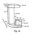
- FIG. 1a-1e An embodiment of a first clip of this invention in a non-assembled configuration is depicted in Figures 1a-1e at 100 and includes a base 102 and arms 104 and 106.
- the base 102 has a rim 110 and a web 112.
- the rim 110 is generally continuous with each of the arms 104 and 106.
- the web 112 is unitary, or otherwise integral, with inner surfaces of the arms 104 and 106 in this embodiment.
- the rim 110 and web 112 define an aperture 114 and the rim 110 further defines a gap 116 at beveled edges 118.
- the arms 104 and 106 respectively, unitarily, or otherwise integrally, extend from the rim 110 and are maintained by the rim 110 and web 112 so as to be resiliently biased in a closed position when fully assembled.
- the arms 104 and 106 in turn, respectively and unitarily (or otherwise integrally) include first gripping portions 120 and 122, angular second portions 124 and 126, second jaw portions 128 and 130, and first jaw portions 132 and 134.
- the first gripping portions 120 and 122 generally taper from a maximum width proximate the junctions with the angular second portions 124 and 126 to a minimum width where the first gripping portions 120 and 122 adjoin the rim 110.
- the first gripping portions 122 and 124 of this embodiment display outer surfaces 136 and 138, respectively. Cavities 140 and 142 and a ridge 144 therebetween are defined by the outer surface 136 and cavities 146 and 148 and a ridge 150 therebetween are defined by the outer surface 138, e.g., to enhance gripping and/or for aesthetic appeal. Obviously, the scope of this invention includes other structures to enhance gripping and/or aesthetic appeal as well.
- the arms 104 and 106 are dimensioned to enable the clip of this invention to be opened with a minimum of effort, yet grip articles being held securely.
- the first gripping portions 120 and 122 may taper from a maximum width between about 17.5 mm and 27.5 mm, between about 20.0 mm and 25 mm, or about 22.5 mm to a minimum width between about 5 mm and 9 mm, between about 6 mm and 8 mm, or about 7 mm.
- the first gripping portions may have a thickness between about 2.5 mm and 4.5 mm, between about 3.0 mm and 4.5 mm, or between about 3.5 mm.
- the web 112 is dimensioned with a length L w and at least one of the flexing portions, e.g., the first gripping portions 120 and 122, is dimensioned with a length L A such that the proper amount of tension is exerted to force the jaw elements together.
- a ratio of the first gripping portions lengths L A to the web length L w is between about 5 and 15, between about 7.5 and 12.5, or about 10.4.
- the dimensions of any specific embodiment of the instant clip may be determined by factors such as the dimensions and weight of articles to be held, materials used in manufacturing the clip of this invention, and the like.
- the second angular portions 124 and 126 obtusely extend from the gripping portions 120 and 122, respectively.
- the second portions may extend generally perpendicularly or acutely from the gripping portions in other embodiments.
- the angular relation of the second portions 124 and 126 to the gripping portions 120 and 122, respectively may be described by respective angles 152 and 154 between the second portions and a longitudinal axis 156.
- the angles 152 and 154 may be between about 33.7 and 53.7 degrees, between about 38.7 and 48.7 degrees, or about 43.7 degrees in the embodiment shown.
- the angular portions 124 and 126 have a maximum width where they unitarily, or otherwise integrally, adjoin the gripping portions 120 and 122 and taper to a minimum width where they unitarily or otherwise integrally, adjoin the second jaw portions 128 and 130. Additionally, the embodiment depicted has the angular portion 124 extending from one-half of the end of the gripping portion 120 and from one-half of the end of the second jaw portion 128. Although not shown, the angular portion 126 may extend from one-half of the gripping portion 122 and from one-half of the end of the second jaw portion 130.
- the second jaw portions 128 and 130 are generally convex as viewed from the side in this embodiment, having a maximum width where they adjoin the angular portions 124 and 126 and tapering to a rounded tip.
- the first jaw portions 132 and 134 unitarily, or otherwise integrally, adjoin the second jaw portions proximate to, but not at, the rounded tips and so as to contact each other at an inward and oblique angle when in a closed, assembled configuration.
- the inward and oblique angle of contact with respect to the first jaw portions 132 and 134 advantageously acts to maintain articles such as gloves secured therebetween by opposing outward forces exerted on the articles.
- the gripping portions 120 and 122 may be dimensioned and made of materials allowing the instant clip to be opened with less force than if the instant jaw portions were not so angled.
- the first jaw portions 132 and 134 may be longitudinally divided into a first-half 166 and a second-half 168.
- the first half 166 terminates in a retaining structure such as a slot 170.
- the second half terminates in a retaining structure such as a projection 172, which extends from a shoulder 174.
- the first jaw portions 132 and 134 are biased in a contacting disposition, such that opposing projections 172 are accommodated in slots 170 and such that shoulders 174 are in abutting contact with the tips of the first halves 166.
- FIG. 3 and 4 Another embodiment of the instant clip is depicted in Figures 3 and 4 at 190.
- the clip 190 differs from the clip 100 in that generally concave (or other arcuate) jaw portions 192 and 194 replace the first and second jaw portions 128, 130, 132, and 134.
- Respective tips 196 and 198 may optionally be stepped or offset when the clip is in a closed position. Retaining structures such as the slots 170 and projections 172 may be present at the tips of the jaw portions in some embodiments.
- the clip of this invention may be made by injection molding and, after being made, is in a non-operational disposition as depicted in Figure 1.
- the resilient materials from which the instant clip is manufactured allow the clip of this invention to be configured into an operational disposition by exerting opposing forces on opposed lateral sides of the gripping portions 120 and 122, thereby forcing them apart laterally, then exerting opposing forces on the outer surfaces of the gripping portions.
- the first jaw portions are forced into axial alignment.
- the first jaw portions are held in a contacting relation by the resiliently biased gripping portions.
- the clip of this invention is biased such that the projections 172 are disposed in slots 170 of opposed first jaw portions 132 and 134.
- the clips 100 and 190 are biased in a closed position and may operably manipulated to an open position during use.
- the first jaw portions 132 and 134 (or 192 and 194) are in a contacting relation such that the projections 172 are disposed in the slots 170 thereof.
- a user manipulates the instant clips to the open position by inwardly exerting forces on the arms 104 and 106 to force the jaw portions apart in a non-contacting relation.
- the user may then allow the clip of this invention to return to the closed position by relaxing the forces exerted on the clip arms and allowing the jaw portions to be displaced toward each other. If an item is not being secured by the clip, the jaw portions will resume the contacting relation.
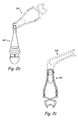
- the jaws will exert a pincher force on the item to retain the item therebetween. Additionally, the securing structures present at the tips of the jaw portions will further secure the item by presenting beveled contacting edges which contact and further retain the item ( Figure 2a).
- a second embodiment of the clip of this invention is depicted generally at 190.
- the clip 190 primarily differs from the clip 100 in that jaw portions 192 and 194 are present in place of the first and second jaw portions described above.
- the jaw portions 192 and 194 are generally arcuate as viewed from the side and, when in a contacting relation, present a generally concave geometry.
- the tips of the jaw portions 192 and 194 are indicated generally at 196 and 198 and, when mated, have a gripping structure to present an optional generally staggered, or stepped, appearance. While not shown, the tips of the jaw portions 192 and 194 may include a retaining structure such as described above with respect to the slot 170 and projection 172.
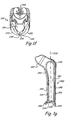
- FIG. 1f and 1g One embodiment of a second clip of this invention is shown in Figures 1f and 1g generally at 200.
- the second clip 200 is unitary, or otherwise integral, but may be considered to include a base 202 and arms 204 and 206.
- the base 202 includes generally lateral, or horizontal, extensions 220 and 222 from a central portion 224.
- the extensions 220 and 222 and the central portion 224 are arrayed around an aperture 226.
- a gap 228 is defined between tips 230 and 232 of respective extensions 220 and 222. However, the tips 230 and 232 may contact each other in some embodiments.
- the base 202 is advantageously angled outwardly with respect to the arms 204 and 206.
- One advantage of angling the base 202 in this manner is that the base is more easily grasped by a user when the clip 200 is being attached or detached from the user's belt.
- Another advantage is that the base 202 extends slightly away from a user as compared to an embodiment in which the base would be linearly aligned with the remainder of the clip 200. Hence the base 202 is more accessible when the clip 100 or 190 is being interlinked or detached from the clip 200 during use.
- the base 202 is further configured so that the gap 228 extends generally parallel to a longitudinal axis 233 of the clip 200. The parallel orientation of the gap 228 facilitates attaching and detaching the clip of this invention, e.g., clip 100 or 190.
- the arm 204 extends from the central portion 224 of the base 202 at a curve 240, and has a generally planar portion 242, terminating at a tip 244.
- the tip 244 may be slightly angled with respect to the planar portion 242 and may be bounded by generally rounded edges.
- the arm 206 extends from the base 202 by means of an angled portion 250, which adjoins a generally planar portion 252.
- the planar portion 252 is generally parallel to the planar portion 242 of the arm 204 in the embodiment depicted.
- the planar portion 252 terminates in a retaining structure such as a generally transverse extension 254.
- the extension 254 is generally curved when viewed from the side and terminates at respective inner and outer edges 256 and 258.
- the inner edge 256 is proximate, but not contacting, an inner surface 260 of the arm 204.
- the arms 204 and 206 are biased such that the inner edge 256 normally contacts the inner surface 260.
- the arm 206 has a shorter length than the arm 204.
- the clip 290 mainly differs from the clip 200 by having generally vertical extensions 292 and 294 from a base 296. As can be seen, the extensions 292 and 294 and the base 296 define the aperture 226. Moreover, the gap 228 is defined generally between the tips 298 and 299 of the respective extensions 292 and 294.
- the clip 200 or 290 is secured to a user by forcing the arms 204 and 206 apart, then sliding, e.g., a belt, to a position between the arms 204 and 206. Finally the clip is secured to the belt allowing the arms to return to a closed position. In the closed position, the extension 254 is either proximate to, or contacting, the inner surface of the opposite arm to prevent the instant clip from being accidentally removed from the belt. In use, a user grasps the extension 254 to force the arms 204 and 206 apart, thereby more easily removing the clip 200 or 290 from a garment, e.g., belt, of the user.
- the instant clips may be detachably linked together.
- the materials used in making the clips of this invention may impart sufficient flexibility to allow the instant clips to be linked together, or detached, as desired.
- the materials utilized in manufacturing may possess sufficient resilience to retain clips of this invention in a linked configuration when being used. As shown in Figures 6a and 6b, when being linked, the gaps of the clips 100, 190, 200, 290 are aligned. Then sufficient force is applied so that the materials defining (surrounding) the apertures is flexed while the instant clips are either interlinked or detached from each other.
- the gaps are dimensioned so that the interlocked clips are retained together unless the gaps are aligned and a force is applied to detach the clips by slightly flexing surfaces 118 slightly apart.
- the clips 100, 190, 200, and 290 may be configured so that the gaps 116 and 228 are not aligned when an interlinked clip is hanging from another of the instant clips, which, in turn, is attached to a garment of a user. This non-alignment of the gaps of interlinked clips prevents the clips from becoming accidentally detached during use.
- the instant assembly may be employed in two configurations in the embodiments described thus far.
- a pair of clips 100 or 190 are employed.
- the clip 100 or 190 is used in combination with the clip 200 (or 290).
- two of the clips 100 or 190 are detachably interlinked.
- One of the clips 100 or 190 may be used to attach the interlinked clips to, e.g., a garment being worn by a user.
- the other of the clips may be used to retain articles, e.g., gloves 400, not being used.
- one of the clips 100 or 190 is attached to the belt loop of the pants of a user and the other of the clips 100 or 190 is used to attach a pair of gloves 400 not being worn.
- the clips are attached by being grasped such that the user's fingers and thumb exert inward forces on the arms 104 and 106 of the clips, thereby forcing the first jaw portions 132 and 134 apart and out of a closed position.
- the gloves (or other items) are then inserted between the jaw portions 132 and 134 and the arms 104 and 106 are allowed to return to the closed position, thereby securing the item between the jaw portions 132 and 134.
- the item is removed by opening the clip to force the jaw portions 132 and 134 apart, thereby allowing the item to be removed from therebetween. Then the arms and jaw portions are allowed to return to the closed position.
- the clip 200 or 290 is attached to a user's garment, e.g., belt as described above. Then one of clips 100 or 190 is detachably linked to the clip 200 or 290 by aligning the gaps and sliding the clips together so that the rim 110 of the clip 100 or 190 is interlinked with the base of the clip 200 or 290 by being disposed in the aperture 226. Detaching interlinked clips is accomplished by again aligning the gaps and sliding the clips apart. The resiliency of the materials and the dimensions of the gaps require sufficient force to be exerted for detaching, thus otherwise retaining the clips in a detachably linked relation.
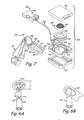
- FIG. 7 Yet another embodiment of this invention is represented in Figure 7 at 300 and includes a reel subassembly 302 and an optional buckle subassembly 304.
- the reel subassembly 302 has respective first (upper) and second (lower) housings 310 and 312, a base 314, a reel 316, a spring 318, and a tether 320.
- the base 314 is dimensioned to be retained between the upper and lower housings 310 and 312.
- the base 314 retains the reel 316 between a generally circular rim 324 and a tract 326, which is generally concentric to the circular rim 324.
- the spring 318 is operably wrapped around a post 328 during assembly.
- outer end 330 of the reel 316 is attached to an inner surface 332 of the reel 316.
- the tether 320 is attached to an outer surface 334 of the reel 316 and wound therearound. The tether 320 is wound or unwound from the reel 316 through a path 336 defined by a path member 338 and the housing 310.
- the reel subassembly 302 is attached, e.g., to a user's belt, by means of a belt clip 340.
- a belt clip 340 One suitable exemplary reel assembly is disclosed in U.S. Patent 5,697,572 , hereby incorporated by reference.
- the optional buckle assembly 304 in the embodiment depicted, includes respective male and female buckle members 344 and 346 and, further optionally, structure for detachably interlinking the clips of this invention such as a ring 348.
- structure for detachably interlinking the instant clips could be square, polygonal or have any suitable geometry.
- the male buckle member 344 has prongs 350 and 352 extending from a base 354.
- the base 354 defines a gap 356.
- the female buckle member 346 includes a housing 360 with opposed lateral openings 362 and 364.
- the male and female members 344 and 346 are locked together by sliding the male member 344 inside the female member 346 until tips 366 and 368 of the respective prongs 350 and 352 are visible in the openings 362 and 364 of the female member 346.
- the prongs 350 and 352 return to an unbiased position with tips 366 and 368 abutting the housing 360 adjacent the openings 362 and 364.
- the male and female members 344 and 346 are separated by forcing the tips 366 and 368 toward each other, thus forcing the tips 366 and 368 from a contacting disposition with respect to the housing 360, then sliding the male member 344 out of the female member 346.
- Exemplary buckle members are disclosed in U.S. Patents 5,590,444 , 3,430,306 , and 4,150,464 , the entire disclosures of each hereby incorporated by reference.
- the buckle assembly may not be present in some embodiments of this invention. If the buckle assembly is not present, the tether 320 may be directly attached to the ring 348. If the ring 348 is also not present, the clip 100 or 190 may be attached directly to the tether 320, e.g., via a loop formed in an end of the tether.
- the reel assembly is attached to a user's garment, e.g., belt, by means of the belt clip 340.
- the clip 100 or 190 may be linked or detached to the ring 348 and to an item to be secured in the same manner as described above.
- the clip 100 or 190 may be used to secure an item, such as a pair of gloves 400.
- the clip may be conveniently extended by exerting a force to unwind the tether 320 from the reel 316. When released, the clip is retracted when the tether is rewound on the reel 316 by the spring 318.
- the presence of the reel assembly allows a user to place the instant clip at almost any desired distance and position when interlinking the instant clip or when attaching detaching an article from the instant clip. Releasing the clip then allows the reel to retract (rewind) the tether so that the clip is disposed adjacent to the reel in a desired position, in which the attached article does not interfere with the activities of the user, but is readily available for use if needed
- Materials suitable for making the instant clips by injection molding include acetyl copolymers, such as polyoxymethylene, available from Hoechst Celanese Corporation. However, a person of ordinary skill in the art will readily understand that other materials may also be suitable. Other suitable materials may be found in the Handbook of Plastics, Elastomers, and Composites, Third Edition, Charles A. Harper, Editor in Chief, McGraw-Hill, New York (1996 ), its contents hereby incorporated by reference.
Landscapes
- Clamps And Clips (AREA)
- Supports Or Holders For Household Use (AREA)
Applications Claiming Priority (1)
| Application Number | Priority Date | Filing Date | Title |
|---|---|---|---|
| US11/132,505 US7213307B2 (en) | 2005-05-19 | 2005-05-19 | Clip |
Publications (2)
| Publication Number | Publication Date |
|---|---|
| EP1723871A2 true EP1723871A2 (fr) | 2006-11-22 |
| EP1723871A3 EP1723871A3 (fr) | 2007-11-14 |
Family
ID=36782544
Family Applications (1)
| Application Number | Title | Priority Date | Filing Date |
|---|---|---|---|
| EP06252395A Withdrawn EP1723871A3 (fr) | 2005-05-19 | 2006-05-05 | Pince |
Country Status (3)
| Country | Link |
|---|---|
| US (2) | US7213307B2 (fr) |
| EP (1) | EP1723871A3 (fr) |
| CA (1) | CA2542561C (fr) |
Cited By (2)
| Publication number | Priority date | Publication date | Assignee | Title |
|---|---|---|---|---|
| WO2011036314A1 (fr) * | 2009-09-22 | 2011-03-31 | Joan Pujal Laborda | Moufle aseptique/protectrice |
| EP2645900A4 (fr) * | 2010-12-01 | 2014-06-11 | Darrell A Moreau | Pince pour attacher des articles ensemble |
Families Citing this family (19)
| Publication number | Priority date | Publication date | Assignee | Title |
|---|---|---|---|---|
| US7213307B2 (en) * | 2005-05-19 | 2007-05-08 | Ergodyne Corporation | Clip |
| WO2009075809A1 (fr) * | 2007-12-10 | 2009-06-18 | Vermillion Kenneth B | Attache |
| USD622584S1 (en) * | 2009-12-03 | 2010-08-31 | Patricia Byron | Decorating clip |
| US9259214B2 (en) * | 2010-05-13 | 2016-02-16 | The Board Of Trustees Of The University Of Illinois | Surgical retractor apparatus and method |
| WO2013073970A2 (fr) * | 2011-09-22 | 2013-05-23 | Fisher & Paykel Healthcare Limited | Bague de tube de verrouillage |
| US9259562B2 (en) * | 2012-07-10 | 2016-02-16 | Lifeline Scientific, Inc. | Cannula |
| JP5827633B2 (ja) * | 2013-01-11 | 2015-12-02 | 株式会社カナエフーズ | 目玉焼き様卵加工食品 |
| US9392864B2 (en) | 2013-12-18 | 2016-07-19 | Chums, Inc. | Accessory fastening device |
| US20150217154A1 (en) | 2014-02-06 | 2015-08-06 | Performance Advantage Company, Inc. | Universal nozzle connector with an adjustable mount |
| US9949558B2 (en) | 2014-08-29 | 2018-04-24 | Chums, Inc. | Accessory fastening devices and methods |
| USD761097S1 (en) * | 2015-04-01 | 2016-07-12 | Tenacious Holdings, Inc. | Magnet grabber |
| USD761098S1 (en) * | 2015-04-01 | 2016-07-12 | Tenacious Holdings, Inc. | Suction cup grabber |
| AU2018208304B2 (en) | 2017-01-13 | 2021-01-21 | 3M Innovative Properties Company | Tether clip |
| US10779599B2 (en) * | 2017-09-26 | 2020-09-22 | Tenacious Holdings, Inc. | Bump cap |
| JP7093265B2 (ja) * | 2018-08-10 | 2022-06-29 | Ykk株式会社 | クリップ |
| USD964146S1 (en) * | 2019-10-12 | 2022-09-20 | Tenacious Holdings, Inc. | Dual swivel clip |
| US11346391B2 (en) * | 2019-10-12 | 2022-05-31 | Tenacious Holdings, Inc. | Dual swivel clip |
| US11406210B2 (en) * | 2020-09-30 | 2022-08-09 | Polyplot Llc | Storage clip |
| US12098499B2 (en) * | 2022-06-13 | 2024-09-24 | Andiamo Home, Llc | Laundry detangling and pairing clips |
Citations (1)
| Publication number | Priority date | Publication date | Assignee | Title |
|---|---|---|---|---|
| DE390558C (de) | 1921-12-13 | 1924-02-26 | Niels Christian Joergensen | Gardinenklammer |
Family Cites Families (59)
| Publication number | Priority date | Publication date | Assignee | Title |
|---|---|---|---|---|
| CA481602A (fr) | 1952-03-11 | Helie Achille | Attache a tirage pour jupes de cyclistes feminines | |
| US926301A (en) | 1909-02-05 | 1909-06-29 | Josef Sveich | Rotary machine. |
| US1878497A (en) * | 1931-09-01 | 1932-09-20 | Lehr Erich | Clip construction |
| US2218932A (en) * | 1938-12-12 | 1940-10-22 | James M Collins | Key holder and chain-attaching means |
| US2513759A (en) * | 1947-01-31 | 1950-07-04 | Tarallo Sebastian | Wire clothespin |
| DE806473C (de) | 1948-10-02 | 1951-06-14 | Marianne Werthmann | Klammer fuer Gardinen, Vorhaenge o. dgl. |
| US2487339A (en) | 1949-08-26 | 1949-11-08 | Victor M Kindlund | Device for embracingly holding gloves |
| US2585089A (en) * | 1949-11-16 | 1952-02-12 | Caldwell Ford Weddington | Resilient clamp |
| US2810176A (en) * | 1956-02-14 | 1957-10-22 | Abdel-Rahman K Gaafar | Tag fastener |
| US2885758A (en) * | 1958-05-15 | 1959-05-12 | Jack P Russo | Clothespin |
| US3140419A (en) | 1960-06-29 | 1964-07-07 | North American Phillips Compan | Electron discharge tube having an anode with cavities |
| US3100324A (en) * | 1961-12-13 | 1963-08-13 | Dominick J Tutino | Clothespin with improved self-storing means |
| US3462809A (en) | 1968-02-09 | 1969-08-26 | Dhj Ind Inc | Garment clip |
| US3521332A (en) * | 1968-03-04 | 1970-07-21 | Roy G Kramer | Double ended clip |
| GB1319612A (en) | 1970-05-19 | 1973-06-06 | Moto Plastics Ltd | Attachment means particularly for securing rooflight to base structures |
| US3691596A (en) * | 1971-01-13 | 1972-09-19 | Judson T Ulansey | Fabric clip |
| US3766613A (en) | 1972-10-02 | 1973-10-23 | Kunreuther And Merfeld | Fabric and garment clip |
| USD249927S (en) | 1976-08-20 | 1978-10-17 | Polachek, Saulsbury & Hough | Biased cup clamp |
| US4226105A (en) | 1978-05-11 | 1980-10-07 | Wehrman Floyd L | Key ring holder |
| US4416266A (en) * | 1981-05-15 | 1983-11-22 | The United States Of America As Represented By The Administrator Of The National Aeronautics And Space Administration | Medical clip |
| US4671281A (en) * | 1982-09-13 | 1987-06-09 | Ethicon, Inc. | Non-metallic, bio-compatible hemostatic clips (one piece wedge clip) |
| AU94419S (en) | 1984-04-04 | 1986-12-04 | Happy Baby Australia Pty Ltd | Nappy clip |
| JPH0134962Y2 (fr) * | 1985-03-15 | 1989-10-25 | ||
| USD307108S (en) | 1987-06-19 | 1990-04-10 | Kitagawa Industries Co., Ltd. | Clamp for clamping wires |
| US4773132A (en) * | 1987-09-25 | 1988-09-27 | Eckels Robert E | Tactile signalling absorption indicator |
| US4966344A (en) * | 1989-08-21 | 1990-10-30 | Gary Products Group, Inc. | Plastic ornament hanger |
| US4990157A (en) * | 1989-11-13 | 1991-02-05 | Robhill Industries Inc. | Soother retainer |
| USD329744S (en) | 1990-03-30 | 1992-09-29 | Hang 5, Inc. | Golf bag tag and glove holder attachment |
| DE4111067A1 (de) * | 1991-01-07 | 1992-07-09 | Svensson A & Co Ab | Vorrichtung und verfahren zum drapieren von vorhaengen |
| US5142807A (en) | 1991-04-15 | 1992-09-01 | Sweet Theodore E | Double-ended gripper device |
| US5109576A (en) | 1991-04-24 | 1992-05-05 | Teekell Gordon E | Closure device |
| US5159731A (en) * | 1991-10-07 | 1992-11-03 | Dereadt Tod H | Clothespin |
| DE4338900A1 (de) * | 1993-04-23 | 1994-10-27 | Turck P C Gmbh & Co Kg | Haltevorrichtung für Schlauch- und andere Leitungen an medizinischen Einrichtungen sowie im Bereich der Kranken- und Altenpflege |
| USD368169S (en) | 1994-11-22 | 1996-03-26 | Coker Jo E | Garment clip |
| US5655270A (en) | 1995-06-05 | 1997-08-12 | Boisvert; Rene G. | Flexible, double ended clip used for attaching identification to clothing |
| US5697572A (en) | 1995-08-09 | 1997-12-16 | Hammerhead Industries, Inc. | Retractable holder |
| US5683405A (en) * | 1995-08-25 | 1997-11-04 | Research Medical Inc. | Vascular occluder |
| US5687458A (en) * | 1996-03-25 | 1997-11-18 | Coker; Jo Ellen | Clip for releasably attaching articles together |
| DE69612488T2 (de) * | 1996-06-25 | 2001-11-29 | Toyota Yuki Co., Ltd. | Schlauchhaltesystem |
| US5722125A (en) | 1996-12-17 | 1998-03-03 | Vasilopoulos; Peter | Securing device for golf club head covers |
| US5884371A (en) | 1997-08-25 | 1999-03-23 | Huggins; Cynthia L. | Lower garment suspension apparatus for assisting disabled persons in dressing |
| US5864925A (en) * | 1997-10-31 | 1999-02-02 | Mcgee; Robert Wayne | Golf glove attachment device |
| JPH11169596A (ja) * | 1997-12-12 | 1999-06-29 | Yamasa Nousan Kk | 物干しクリップ |
| US5944729A (en) * | 1997-12-12 | 1999-08-31 | Scanlan International, Inc. | Vascular occlusion clamp with radiopaque retrieval, identification and marking string |
| US6056173A (en) | 1998-03-02 | 2000-05-02 | Jodon Engineering Associates, Inc. | Holding device |
| US6212688B1 (en) | 1999-01-27 | 2001-04-10 | Henry E. Leslie | Firefighter's glove holder |
| US6161266A (en) * | 1999-02-18 | 2000-12-19 | National Molding Corporation | Modular attachment system |
| US6256840B1 (en) | 1999-08-07 | 2001-07-10 | Paul Elliott | Swing towel |
| US6216319B1 (en) | 1999-08-16 | 2001-04-17 | Oscar K. Elkins | Tool tether |
| US6631538B1 (en) | 1999-11-10 | 2003-10-14 | Kathleen Cosgriff Carr | Self-closing clasp assembly |
| US6682249B2 (en) | 2000-12-14 | 2004-01-27 | Peter W. Rietz | Reconnectable breakaway rope safety connector |
| US6598273B2 (en) * | 2001-09-10 | 2003-07-29 | J.A.M. Plastics, Inc. | Lanyard buckle connector |
| USD487723S1 (en) * | 2001-11-29 | 2004-03-23 | Kabushiki Kaisha Toshiba | Photoelectric conversion device |
| US6691374B2 (en) | 2002-06-18 | 2004-02-17 | Mark Coyne | Eyeglasses holder |
| USD478723S1 (en) | 2002-08-27 | 2003-08-26 | Fred T. Blanton | Clip for gloves or the like |
| US6929209B2 (en) * | 2003-07-14 | 2005-08-16 | David Baumgarten | Self-orienting retractable ID card holder |
| AU2004268491B2 (en) * | 2003-09-02 | 2010-03-04 | Kenneth B. Vermillion | Belt clip with breakaway safety feature |
| USD515412S1 (en) | 2005-03-11 | 2006-02-21 | Sherwood Services Ag | Drape clip |
| US7213307B2 (en) * | 2005-05-19 | 2007-05-08 | Ergodyne Corporation | Clip |
-
2005
- 2005-05-19 US US11/132,505 patent/US7213307B2/en not_active Expired - Lifetime
-
2006
- 2006-04-10 CA CA2542561A patent/CA2542561C/fr not_active Expired - Lifetime
- 2006-05-05 EP EP06252395A patent/EP1723871A3/fr not_active Withdrawn
-
2007
- 2007-02-21 US US11/709,321 patent/US7581292B2/en not_active Expired - Lifetime
Patent Citations (1)
| Publication number | Priority date | Publication date | Assignee | Title |
|---|---|---|---|---|
| DE390558C (de) | 1921-12-13 | 1924-02-26 | Niels Christian Joergensen | Gardinenklammer |
Cited By (3)
| Publication number | Priority date | Publication date | Assignee | Title |
|---|---|---|---|---|
| WO2011036314A1 (fr) * | 2009-09-22 | 2011-03-31 | Joan Pujal Laborda | Moufle aseptique/protectrice |
| EP2645900A4 (fr) * | 2010-12-01 | 2014-06-11 | Darrell A Moreau | Pince pour attacher des articles ensemble |
| US9375074B2 (en) | 2010-12-01 | 2016-06-28 | Darrell A. Moreau | Clip for attaching articles together |
Also Published As
| Publication number | Publication date |
|---|---|
| CA2542561C (fr) | 2011-11-22 |
| US20070204440A1 (en) | 2007-09-06 |
| US20060260105A1 (en) | 2006-11-23 |
| US7581292B2 (en) | 2009-09-01 |
| US7213307B2 (en) | 2007-05-08 |
| CA2542561A1 (fr) | 2006-11-19 |
| EP1723871A3 (fr) | 2007-11-14 |
Similar Documents
| Publication | Publication Date | Title |
|---|---|---|
| US7581292B2 (en) | Clip | |
| CN112089157B (zh) | 搭扣 | |
| US5669119A (en) | Cord lanyard | |
| EP1018609B1 (fr) | Dispositif de verrouillage de ruban | |
| US6161266A (en) | Modular attachment system | |
| EP3165117B1 (fr) | Boucle | |
| US4049357A (en) | Sliding coupling device for a lanyard or the like | |
| EP3165118B1 (fr) | Boucle | |
| EP0909538B1 (fr) | Système d'attache modulaire pour chapeaux, badges et similaires | |
| US6510592B1 (en) | Clip for attaching pouches and similar devices | |
| US6615460B1 (en) | Optionally manual or automatic breakaway lanyard buckle | |
| US20030010057A1 (en) | Necklace mount | |
| KR100263026B1 (ko) | 연결구를 갖춘 코드 | |
| WO1990009120A1 (fr) | Attache reglable deliable portee au cou | |
| CN101296632A (zh) | 可互换的珠宝嵌入物和用于容纳该嵌入物的物品 | |
| US5971458A (en) | Clothing carrier | |
| US20100257898A1 (en) | Magnetic Jewelry Clasp and Interchangeable Pendant System | |
| US5784760A (en) | Retaining mechanism for securing connecting members | |
| US20140076945A1 (en) | Lanyard with tool coupled thereto and related system and method | |
| US20050035164A1 (en) | Belt clip and locking fastener for selectively securing an electronic device | |
| US20030121125A1 (en) | Breakaway gripper-style lanyard connector | |
| KR890004095Y1 (ko) | 스냅후크 | |
| GB2264142A (en) | Clip | |
| WO2001024656A1 (fr) | Ensemble de fixation pour dispositifs de telecommunications personnels | |
| KR101507279B1 (ko) | 장신구 고정용 기구 |
Legal Events
| Date | Code | Title | Description |
|---|---|---|---|
| PUAI | Public reference made under article 153(3) epc to a published international application that has entered the european phase |
Free format text: ORIGINAL CODE: 0009012 |
|
| AK | Designated contracting states |
Kind code of ref document: A2 Designated state(s): AT BE BG CH CY CZ DE DK EE ES FI FR GB GR HU IE IS IT LI LT LU LV MC NL PL PT RO SE SI SK TR |
|
| AX | Request for extension of the european patent |
Extension state: AL BA HR MK YU |
|
| 17P | Request for examination filed |
Effective date: 20070502 |
|
| PUAL | Search report despatched |
Free format text: ORIGINAL CODE: 0009013 |
|
| AK | Designated contracting states |
Kind code of ref document: A3 Designated state(s): AT BE BG CH CY CZ DE DK EE ES FI FR GB GR HU IE IS IT LI LT LU LV MC NL PL PT RO SE SI SK TR |
|
| AX | Request for extension of the european patent |
Extension state: AL BA HR MK YU |
|
| AKX | Designation fees paid |
Designated state(s): DE ES FR GB IT |
|
| 17Q | First examination report despatched |
Effective date: 20080630 |
|
| GRAP | Despatch of communication of intention to grant a patent |
Free format text: ORIGINAL CODE: EPIDOSNIGR1 |
|
| RAP1 | Party data changed (applicant data changed or rights of an application transferred) |
Owner name: TENACIOUS HOLDINGS, INC |
|
| GRAC | Information related to communication of intention to grant a patent modified |
Free format text: ORIGINAL CODE: EPIDOSCIGR1 |
|
| GRAC | Information related to communication of intention to grant a patent modified |
Free format text: ORIGINAL CODE: EPIDOSCIGR1 |
|
| STAA | Information on the status of an ep patent application or granted ep patent |
Free format text: STATUS: THE APPLICATION IS DEEMED TO BE WITHDRAWN |
|
| 18D | Application deemed to be withdrawn |
Effective date: 20111119 |