EP1724018A2 - Substrats et dispositif d'essai bio ainsi que procédé de fabrication des substrats - Google Patents
Substrats et dispositif d'essai bio ainsi que procédé de fabrication des substrats Download PDFInfo
- Publication number
- EP1724018A2 EP1724018A2 EP06252486A EP06252486A EP1724018A2 EP 1724018 A2 EP1724018 A2 EP 1724018A2 EP 06252486 A EP06252486 A EP 06252486A EP 06252486 A EP06252486 A EP 06252486A EP 1724018 A2 EP1724018 A2 EP 1724018A2
- Authority
- EP
- European Patent Office
- Prior art keywords
- substrate
- group
- reaction regions
- information
- substance
- Prior art date
- Legal status (The legal status is an assumption and is not a legal conclusion. Google has not performed a legal analysis and makes no representation as to the accuracy of the status listed.)
- Granted
Links
Images




Classifications
-
- G—PHYSICS
- G01—MEASURING; TESTING
- G01N—INVESTIGATING OR ANALYSING MATERIALS BY DETERMINING THEIR CHEMICAL OR PHYSICAL PROPERTIES
- G01N35/00—Automatic analysis not limited to methods or materials provided for in any single one of groups G01N1/00 - G01N33/00; Handling materials therefor
- G01N35/00029—Automatic analysis not limited to methods or materials provided for in any single one of groups G01N1/00 - G01N33/00; Handling materials therefor provided with flat sample substrates, e.g. slides
- G01N35/00069—Automatic analysis not limited to methods or materials provided for in any single one of groups G01N1/00 - G01N33/00; Handling materials therefor provided with flat sample substrates, e.g. slides whereby the sample substrate is of the bio-disk type, i.e. having the format of an optical disk
-
- G—PHYSICS
- G01—MEASURING; TESTING
- G01N—INVESTIGATING OR ANALYSING MATERIALS BY DETERMINING THEIR CHEMICAL OR PHYSICAL PROPERTIES
- G01N33/00—Investigating or analysing materials by specific methods not covered by groups G01N1/00 - G01N31/00
- G01N33/48—Biological material, e.g. blood, urine; Haemocytometers
- G01N33/50—Chemical analysis of biological material, e.g. blood, urine; Testing involving biospecific ligand binding methods; Immunological testing
- G01N33/53—Immunoassay; Biospecific binding assay; Materials therefor
-
- B—PERFORMING OPERATIONS; TRANSPORTING
- B01—PHYSICAL OR CHEMICAL PROCESSES OR APPARATUS IN GENERAL
- B01L—CHEMICAL OR PHYSICAL LABORATORY APPARATUS FOR GENERAL USE
- B01L3/00—Containers or dishes for laboratory use, e.g. laboratory glassware; Droppers
- B01L3/50—Containers for the purpose of retaining a material to be analysed, e.g. test tubes
- B01L3/508—Rigid containers without fluid transport within
- B01L3/5085—Rigid containers without fluid transport within for multiple samples, e.g. microtitration plates
-
- B—PERFORMING OPERATIONS; TRANSPORTING
- B29—WORKING OF PLASTICS; WORKING OF SUBSTANCES IN A PLASTIC STATE IN GENERAL
- B29C—SHAPING OR JOINING OF PLASTICS; SHAPING OF MATERIAL IN A PLASTIC STATE, NOT OTHERWISE PROVIDED FOR; AFTER-TREATMENT OF THE SHAPED PRODUCTS, e.g. REPAIRING
- B29C45/00—Injection moulding, i.e. forcing the required volume of moulding material through a nozzle into a closed mould; Apparatus therefor
- B29C45/17—Component parts, details or accessories; Auxiliary operations
- B29C45/26—Moulds
- B29C45/37—Mould cavity walls, i.e. the inner surface forming the mould cavity, e.g. linings
- B29C45/372—Mould cavity walls, i.e. the inner surface forming the mould cavity, e.g. linings provided with means for marking or patterning, e.g. numbering articles
-
- G—PHYSICS
- G01—MEASURING; TESTING
- G01N—INVESTIGATING OR ANALYSING MATERIALS BY DETERMINING THEIR CHEMICAL OR PHYSICAL PROPERTIES
- G01N33/00—Investigating or analysing materials by specific methods not covered by groups G01N1/00 - G01N31/00
- G01N33/48—Biological material, e.g. blood, urine; Haemocytometers
- G01N33/50—Chemical analysis of biological material, e.g. blood, urine; Testing involving biospecific ligand binding methods; Immunological testing
- G01N33/53—Immunoassay; Biospecific binding assay; Materials therefor
- G01N33/543—Immunoassay; Biospecific binding assay; Materials therefor with an insoluble carrier for immobilising immunochemicals
- G01N33/551—Immunoassay; Biospecific binding assay; Materials therefor with an insoluble carrier for immobilising immunochemicals the carrier being inorganic
- G01N33/553—Metal or metal coated
-
- B—PERFORMING OPERATIONS; TRANSPORTING
- B01—PHYSICAL OR CHEMICAL PROCESSES OR APPARATUS IN GENERAL
- B01L—CHEMICAL OR PHYSICAL LABORATORY APPARATUS FOR GENERAL USE
- B01L2300/00—Additional constructional details
- B01L2300/02—Identification, exchange or storage of information
-
- B—PERFORMING OPERATIONS; TRANSPORTING
- B01—PHYSICAL OR CHEMICAL PROCESSES OR APPARATUS IN GENERAL
- B01L—CHEMICAL OR PHYSICAL LABORATORY APPARATUS FOR GENERAL USE
- B01L2300/00—Additional constructional details
- B01L2300/06—Auxiliary integrated devices, integrated components
- B01L2300/0627—Sensor or part of a sensor is integrated
- B01L2300/0645—Electrodes
-
- B—PERFORMING OPERATIONS; TRANSPORTING
- B01—PHYSICAL OR CHEMICAL PROCESSES OR APPARATUS IN GENERAL
- B01L—CHEMICAL OR PHYSICAL LABORATORY APPARATUS FOR GENERAL USE
- B01L2300/00—Additional constructional details
- B01L2300/08—Geometry, shape and general structure
- B01L2300/0803—Disc shape
- B01L2300/0806—Standardised forms, e.g. compact disc [CD] format
-
- B—PERFORMING OPERATIONS; TRANSPORTING
- B01—PHYSICAL OR CHEMICAL PROCESSES OR APPARATUS IN GENERAL
- B01L—CHEMICAL OR PHYSICAL LABORATORY APPARATUS FOR GENERAL USE
- B01L2300/00—Additional constructional details
- B01L2300/08—Geometry, shape and general structure
- B01L2300/0887—Laminated structure
-
- B—PERFORMING OPERATIONS; TRANSPORTING
- B01—PHYSICAL OR CHEMICAL PROCESSES OR APPARATUS IN GENERAL
- B01L—CHEMICAL OR PHYSICAL LABORATORY APPARATUS FOR GENERAL USE
- B01L2300/00—Additional constructional details
- B01L2300/16—Surface properties and coatings
- B01L2300/168—Specific optical properties, e.g. reflective coatings
-
- B—PERFORMING OPERATIONS; TRANSPORTING
- B01—PHYSICAL OR CHEMICAL PROCESSES OR APPARATUS IN GENERAL
- B01L—CHEMICAL OR PHYSICAL LABORATORY APPARATUS FOR GENERAL USE
- B01L2400/00—Moving or stopping fluids
- B01L2400/04—Moving fluids with specific forces or mechanical means
- B01L2400/0403—Moving fluids with specific forces or mechanical means specific forces
- B01L2400/0415—Moving fluids with specific forces or mechanical means specific forces electrical forces, e.g. electrokinetic
-
- B—PERFORMING OPERATIONS; TRANSPORTING
- B29—WORKING OF PLASTICS; WORKING OF SUBSTANCES IN A PLASTIC STATE IN GENERAL
- B29C—SHAPING OR JOINING OF PLASTICS; SHAPING OF MATERIAL IN A PLASTIC STATE, NOT OTHERWISE PROVIDED FOR; AFTER-TREATMENT OF THE SHAPED PRODUCTS, e.g. REPAIRING
- B29C45/00—Injection moulding, i.e. forcing the required volume of moulding material through a nozzle into a closed mould; Apparatus therefor
- B29C45/17—Component parts, details or accessories; Auxiliary operations
- B29C45/26—Moulds
- B29C45/263—Moulds with mould wall parts provided with fine grooves or impressions, e.g. for record discs
-
- G—PHYSICS
- G01—MEASURING; TESTING
- G01N—INVESTIGATING OR ANALYSING MATERIALS BY DETERMINING THEIR CHEMICAL OR PHYSICAL PROPERTIES
- G01N35/00—Automatic analysis not limited to methods or materials provided for in any single one of groups G01N1/00 - G01N33/00; Handling materials therefor
- G01N35/00584—Control arrangements for automatic analysers
- G01N35/00722—Communications; Identification
- G01N35/00732—Identification of carriers, materials or components in automatic analysers
- G01N2035/00742—Type of codes
- G01N2035/00772—Type of codes mechanical or optical code other than bar code
Definitions
- This invention relates to a technique related to a substrate for bioassay. More particularly, the invention relates to a substrate and device suited for bioassay for measuring and detecting interaction between substances and also to a method for making the substrate.
- substrates that are called a DNA chip or DNA microarray (hereinafter referred generically to DNA chip) wherein a given DNA is (in full length or partly) microsequenced have been utilized for mutation evolution, SNP's (single nucleotide polymorphisms) analysis, a frequency analysis of genomic expression and the like and are now being used widely in other fields of drug discovery, clinical diagnosis, pharmacogenomics, forensic medicine and the like.
- DNA chip DNA microarray
- the DNA chip it is general to fix a nucleic acid strand called probe against a surface site of a reaction field provided on a substrate and detect hybridization between the probe nucleic acid strand waiting for at the reaction field and a fluorescence-labeled target nucleic acid strand by measuring an intensity of target nucleic acid-derived fluorescence.
- Patent Document 2 Japanese Laid-open Patent Application No. 2005-3450 discloses a DNA chip wherein a reaction region (corresponding to a data region) serving as a field of hybridization and address pits for obtaining positional information of the reaction region and rotational synchronism information on the same plane of a disk-shaped substrate (see Fig. 1 of Patent Document 2).
- Patent Document 3 Japanese Laid-open Patent Application No. 2004-93548 proposes a disk-shaped medium wherein microcapillaries capable of isolating a sample component by electrophoresis are formed.
- reaction regions corresponding to data regions of an optical disk and a group of information pits providing positional information of the reaction regions and substance information are formed on the same plane or surface of a substrate, there arises a technical problem in that since a solvent is stored in the reaction regions of the substrate for bioassay, a tracking servo following the information pit group is susceptible to receive a disturbance owing to the presence of the reaction regions.
- reaction regions makes it unstable to read the positional information and substance information of the information pit group.
- a technical problem is involved in that with a substrate arrangement wherein an electrode layer (conductive layer) is formed on the surface where the information pit group has been formed, reading of information from the information pit group becomes more instabilized.
- embodiments of the invention seek to provide a substrate for bioassay that enables an optical pickup means of the type similar to that of an optical disk reproducing apparatus to obtain information related to the interaction between substances from reaction regions on a substrate and also to more stably obtain information from an information pit group formed on the substrate.
- Embodiments of the invention contemplates to provide a substrate for bioassay, which comprises a group of reaction regions serving as a field where interaction between substances proceeds and a group of information pits used to obtain positional information of the respective region regions and/or substance information used in the reaction regions wherein the substrate is so arranged that the group of reaction regions and the group of information pits are not formed on the same substrate surface.
- the arrangement where the group of reaction regions and the group of information pits are not formed on the same substrate surface should not be construed as limited narrowly.
- the group of reaction regions are formed on one substrate surface and the group of information pits are formed on or in the other surface, with which it is designed not to form the group of reaction regions and the group of information pits on or in the same substrate surface.
- a substrate in which a group of reaction regions are formed at an upper surface side and a group of information pits are formed at a lower surface side, under which an optically transparent substrate capable of transmitting light of a given wavelength (e.g. fluorescence exciting light, tracking servo light, focusing servo light or the like) may be disposed on the lower surface side.
- an optical pickup operation can be performed from the lower surface side of the substrate.
- a conductive layer acting as an electrode may be formed on the substrate surface where the group of reaction regions have been formed. Since no group of information pits are formed on this substrate surface, reading of the group of information pits suffers no influence of the conductive layer, thus being stabilized.
- the use of the conductive layer as an electrode for application of an electric field is optional.
- opposed electrodes are formed using the conductive layer and a conductive cover substrate covering the group of reaction regions, under which an electric field may be applied to individual reaction regions via the opposed electrodes.
- the cover substrate may be formed with holes, through which a sample solution is introduced into individual reaction regions.
- the shape of the substrate for bioassay according to embodiments of the invention is not critical and preferably includes a form of disk.
- an optical pickup means as used in optical disks such as CD, CVD and the like may be adopted.
- Individual reaction regions of the reaction region group disposed at the substrate surface allow a probe substance waiting for a target substance, which serves as a counterpart of an interaction such as hybridization, to exist in a free or fixed state.
- the interaction can be detected.
- fluorescence information obtained from a fluorescent substance specifically bound to a product obtained through the interaction between the probe substance and the target substance the interaction can be detected.
- the embodiments of invention provide a bioassay device which comprises a fluorescence detection unit for detecting a fluorescence intensity by irradiating fluorescence exciting light against a group of reaction regions provided at a substrate for bioassay so as to obtain a fluorescence serving as occurrence information of interaction, under which the fluorescence is focused, and a servo unit for obtaining positional information of the respective reaction regions of the reaction region group and/or substance information employed in the respective reaction regions by irradiating a laser beam of a given wavelength against the group of information pits to perform focusing servo and tracking servo.
- a fluorescence detection unit for detecting a fluorescence intensity by irradiating fluorescence exciting light against a group of reaction regions provided at a substrate for bioassay so as to obtain a fluorescence serving as occurrence information of interaction, under which the fluorescence is focused
- a servo unit for obtaining positional information of the respective reaction regions of the reaction region group and/or substance information
- the measurement of fluorescence after the interaction in the reaction regions can be effected by use of an optical pickup as used in existing optical disk reproducing apparatuses to obtain data of a detected fluorescence intensity related with the positional information of the respective reaction regions and substance-related information such as of a probe substance.
- embodiments of the invention provide a method for making a substrate for bioassay, which is characterized by comprising subjecting a synthetic resin material to injection molding to provide a substrate that is provided with a group of reaction regions serving as a field where the interaction between substances proceeds and a group of information pits used to obtain positional information of the reaction regions and/or substance information used within the reaction regions in such a way that the group of reaction region are formed on one surface and the group of the information pits are formed on the other surface and both surfaces are simultaneously, integrally molded.
- the simultaneous integral molding of both sides ensures positional registration between the group of reaction regions and the group of information pits in high accuracy.
- reaction is intended to widely mean noncovalent bond, covalent bond, chemical bond including hydrogen bond or dissociation between substances and, for example, mean hybridization between nucleic acid molecules, interaction between proteins, chemical bond between substances in antigen-antibody reaction or dissociation.
- hybridization means a reaction for forming a complementary strand (a double strand) between complementary base sequence structures.
- probe substance means a substance that is present in a solvent stored or kept in a reaction region and functions as a probe (detector) for detecting a substance (target substance) to specifically interact with the probe substance and is allowed to exist in the reaction regions in a free state or exist as fixed at one end thereof to a solid phase surface.
- target substance is a substance provided for a sample for the purpose of checking whether a specific interaction with the above-defined probe substance is carried out.
- nucleic acid strand means a polymer (a nucleotide strand) of nucleoside phosphate wherein purine or a pyrimidine base and sugar are subjected to glucoside bond and widely covers DNA's (in full length or fragments thereof) that are polymers of oligonucleotides including probe DNA, polynucleotide or purine nucleotide and pyrimidine nucleotide, cDNA obtained by reverse transcript, RNA, polyamide nucleotide derivatives (PNA) and the like.
- PNA polyamide nucleotide derivatives
- reaction region is a region capable providing a field of interaction such as hybridization and one instance includes a reaction field having a well form capable of storing a liquid phase or gel therein.
- information pit is a site formed in a substrate surface and capable of being utilized for obtaining positional information of reaction regions, information related to a substance existing in a reaction region, and information of tacking or focusing.
- Pit arrays for information can be in conformity with the format, for example, of CD (compact disk) or DVD (digital versatile disk).
- substrate for bioassay means a substrate that allows interaction between substances in given reaction regions of the substrate to proceed so as to detect the interaction and encompasses a wide variety of substrates irrespective of the types of substances without objection to the detection principle of the interaction.
- the substrate for bioassay includes, at least, a DNA chip (a DNA microarray) wherein a nucleic acid strand such as a DNA probe is fixed in a microsequence and a protein chip suited to detect an interaction between proteins or an antigen-antibody reaction.
- the substrate is so arranged that the group of reaction regions and the group of information pits are not formed on the same substrate surface, so that data information, related to the interaction between substances, from the reaction regions on the substrate can be obtained by an optical pickup means of the type as used in optical disk reproducing apparatuses and simultaneously, information from the group of information pits formed on the substrate can be more stably obtained.
- Fig. 1 is a plan view, as viewed from above, of a substrate for bioassay according to one embodiment of the invention.
- a substrate for bioassay indicated at 1 is one which is used to detect interaction between substances.
- the substrate is made of a disk-shaped plate similar to optical disks such as CD (compact disk), DVD (digital versatile disk) and the like.
- CD compact disk
- DVD digital versatile disk
- the substrate for bioassay of embodiments of the invention is not limited to a disk-shaped form in a narrow sense, it is as a matter of fact that if it has a disk shape, apparatuses and techniques used for existing optical,disks can be conveniently employed.
- a central hole 2 is formed at the center of the substrate 1 for bioassay.
- a chucking mechanism for holding and rotating the substrate 1 is inserted into the central hole 2.
- the substrate 1 for bioassay is broadly constituted of a lower side multi-layered substrate 11 and a cover substrate 12 having an outer diameter smaller than the lower substrate 11.
- the cover substrate 12 has a multitude of holes 121, which correspond, in number, to reaction regions 3 (not shown in Fig. 1), radially arrayed as viewed from above (see Fig. 1). It will be noted that the cover substrate 12 is utilized as an electrode in this embodiment and is formed of a conductive material.
- Fig. 2 is a sectional view of the substrate as viewed along the direction of arrows A-A
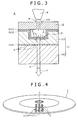
- Fig. 3 is an enlarged sectional view of a portion B in Fig. 2.
- the lower side multi-layered substrate 11 is formed with a multitude of wells serving as reaction regions 3,3... at the upper surface side thereof and is provided, at the lower surface side thereof, with an optically transparent, first substrate 111 having a multitude of information pits 4,4... formed in arrays.
- the first substrate 111 is provided with an optically transparent, second substrate 112 at the lower side thereof.
- a reflection film 1111 (see Fig. 3) having a specified reflectance is formed on the surface of the first substrate 111 where the information pits 4 are formed. This reflection film 1111 is bonded to the upper surface of the second substrate 112. The reflection film 1111 serves to selectively reflect tracking servo light or the like irradiated toward the information pits 4.
- a necessary number of microwells are formed at the upper surface side of the first substrate 111, and the well functions as a reaction region 3 that is a field of interaction between substances.
- This well is so designed as to have a depth and a size (e.g. a diameter of 500 ⁇ m and a dept of 5 ⁇ m) sufficient to permit a liquid, such as a sample solution, to be kept therein when such a liquid is dropped.
- the reaction regions 3 on the first substrate 111 may be in a mutually independent well form as shown in Fig. 2.
- the regions may be formed as channels C extended radially from the center and disposed at given intervals along a peripheral direction (se Fig. 4).
- the first substrate 111 is formed, on the upper surface thereof, with a transparent electrode layer 1112 made of ITO (indium tin oxide) or the like in a thickness, for example, of about 150 nm.
- a solid phase layer 1113 suited to fix a probe substance X is further stacked on the transparent electrode layer 1112.
- the solid phase layer 1113 is formed of a material suited to fix the probe substance X at one terminal of the molecule thereof.
- SiO 2 capable of surface modification with a silane compound is formed as a film in a thickness of about 50 nm.
- the solid phase layer 1113 formed such as of SiO 2 functions as an insulating layer and thus, can prevent occurrence of an electrochemical reaction with an ionic solution that may be stored in the reaction region 3, in some case.
- the solid phase layer 1113 is exposed to a bottom 21 (see Fig. 3) of the reaction region 3, and the exposed surface portion is surface-treated, for example, with a silane coupling agent.
- the probe substance X can be chemically joined at a modified terminal functional group thereof with a free amino group of the silane coupling agent. That is, the probe substance can be fixed. Alternatively, the probe X may be fixed by use of a diazo coupling reaction.
- the first substrate 111 and second substrate 112 are, respectively, formed of a material or materials permitting transmission of fluorescence exciting light P exciting a fluorescent material in the reaction region 3 and fluorescence F that is generated by excitation with the fluorescence exciting light P (see Fig. 3).
- the first substrate 111 and the second substrate 112 are favorably constituted of a material or materials such as an optically transparent synthetic resin, glass or the like, respectively. If the information pits 4 are in a CD format, the second substrate is set at a thickness of 1.2 mm. Likewise, if the information pits 4 are in a DVD format, the second substrate is set at a thickness of 0.6 mm.
- the first substrate 111 is so arranged as to separately form a group of reaction regions 3 and a group of information pits 4 at the front surface (upper surface) and back surface (lower surface) thereof, respectively.
- the substrate 111 of this arrangement is conveniently manufactured by injection molding of a thermoplastic resin according to a simultaneous, doublesides molding process using stampers (molds) Z, Z separately engraved with individual patterns of the reaction regions 3 and the information pits 4. The reason for this is that the molding is completed in one step and is thus simple and positional registration of the reaction regions 3 and the information pits 4 can be performed in high accuracy.
- the cover substrate 12 can be made up entirely of a metallic substrate or sheet (see Fig. 3). Instead, a synthetic resin substrate or sheet which is formed at part thereof with an electrode layer such as an ITO film or the like may be used for this purpose (not shown).
- This cover substrate 12 may be bonded to the first substrate 111 after having been positionally registered, or may be mounted to the first substrate 111 in the course of application of an electric field to the reaction regions 3 or when interaction is allowed to proceed, whichever may be selected depending on the purpose.
- the cover substrate 12 is formed, at the center thereof, with the hole 121, through which a sample solution M is introduced into the reaction region 3.
- the hole 121 is so formed as having a size (or a diameter) that is smaller than an opening of the reaction region 3 and is sufficient to have the sample solution M introduced into the well in high accuracy.
- symbol N shown in Fig. 3 indicates a nozzle for dropping the sample solution M toward the hole 121.
- a sample solution containing several types of probe substances X is introduced into an intended reaction region 3 or a group of reaction regions from the nozzle N through the hole 121 of the cover substrate 12, and the respective probe substances X are fixed to the bottoms 31 of individual reaction regions 3. Subsequently, according to an introduction procedure as with the probe substance X, a sample solution containing a target substance Y labeled with a fluorescent substance f is introduced into the respective reaction regions 3 to permit interaction between the substances X and Y to proceed.
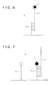
- Fig. 6 there is schematically shown how a probe nucleic acid strand X 1 and a fluorescence-labeled target nucleic acid strand Y 1 are hybridated (an instance of interaction) in the reaction region 3 to form a complementary strand (double strand).
- the fluorescence information from the target nucleic acid strand Y 1 becomes information showing occurrence of hybridization. More particularly, an intense fluorescence can be measured in the reaction region wherein there exist the target nucleic acid strand Y 1 and the probe nucleic acid strand X 1 having a complementary base sequence.
- the hybridization may be detected by labeling the probe nucleic acid strand X 1 with the fluorescent substance f and measuring the resulting fluorescence.
- the probe nucleic acid strand X 1 may be labeled with the fluorescent substance f in such a way that fluorescence is emitted only when hybridization proceeds, under which fluorescence from an intercalator I is measured to detect hybridization.
- hybridization may be detected by introducing a fluorescent intercalator I, which is specifically bound to a complementary strand portion, into the reaction region 3 and measuring fluorescence from the intercalator.
- the introduction timing of the intercalator I is not critical.
- the intercalator may be introduced simultaneously with the target nucleic acid strand Y 1 or may be introduced after progress of hybridization.
- the substrate 1 for bioassay is so arranged as to have the transparent electrode layer stacked on the first substrate 111 and the cover substrate 12 serving as a counter electrode, so that an electric filed can be applied to the reaction region 3 via the counter electrode.
- hybridization may be allowed to proceed under conditions where a high frequency AC voltage of 5V and 1 MHz is applied, thereby applying an electric field of about 1 V/ ⁇ m to the reaction regions 3.
- electrophoresis For the electrodynamic action of application of an electric field on the interaction between substances, mention is made of electrophoresis, dielectrophoresis and the like. These electrodyanamic action may be appropriately selected depending on the type of interaction and the purpose, thereby achieving an improved probability of association between substances and dissolution of a steric trouble upon the interaction. Hence, the efficiency of interaction can be enhanced and high-speed assay operations can be attained, thereby enabling one to increase a detection accuracy of interaction.
- an uneven electric field can be more effectively established in the vicinity of the transparent electrode layer 1112 when the transparent electrode layer 111 is partly formed at the bottom of the reaction region 3 or at part of the bottom than when the transparent layer 1112 is provided wholly over the first substrate 111.
- the electrophoretic action can be effectively utilized.
- Such a partial transparent electrode layer 1112 can be made using a metal mask having openings at portions corresponding to the reaction regions 3, for example, when ITO is sputtered on the first substrate 111 in the form of a film.
- the substrate 1 for bioassay has the information pits 4 capable of reading by irradiating a laser beam for CD or DVD from the lower side thereof.
- the positional information (address information) of individual reaction regions 3 of the substrate 1 can be optically read, thereby making it possible to identify which reaction region of the group of reaction regions 3 is subjected to fluorescence detection operations.
- a reproduction system as used in an optical disk system there can be detected a focusing servo control for controlling a focusing position of a laser beam, a positioning servo control for controlling an irradiation position of a laser beam along a radial direction and a dropping position of a dropping device such as the nozzle N, and the information pits 4.
- a laser beam can be irradiated only against a specified reaction region 3 to effect a fluorescence detection operation.
- FIG. 9 is a view showing an embodiment of a bioassay apparatus suitable for carrying out the procedure.
- a chucking mechanism 5 like an optical disk drive, as shown in Fig. 1.
- This chucking mechanism 5 is connected to a rotary drive shaft and has a central shaft 51, a turn plate 52 that is formed vertically to the center shaft and supports the substrate 1 for bioassay from the lower surface side, and a chucking claw 53 holding the substrate 1 from the upper surface side (see Fig. 9).
- the turn plate 52 and the chucking claw 53 are, respectively, attached to the central shaft 51 and rotated along with the central shaft 51.
- a sample solution containing a probe DNA modified with a specific type of functional group e.g. an amino group or a carboxyl group
- a specific type of functional group e.g. an amino group or a carboxyl group
- the substrate 1 for bioassay Upon the feed, the substrate 1 for bioassay is so rotated that the probe DNA is dropped into individual reaction regions while controlling the relative position between the specified reaction region 3 and the dropping nozzle N. According to such a dropping operation as mentioned above, several types of probe DNA's are, respectively, dropped in predetermined reaction regions 3 of the substrate 1 provided that one type of probe DNA has to be fed into one reaction region 3.
- Whether which types of probe DNA's are dropped in the respective region regions is determined by preparing beforehand an arrangement map showing the relationship between the reaction regions 3 and the probe DNA's and controlling the dropping based on the arrangement map. Under conditions where give types of DNA solutions are, respectively, filled in all the reaction regions 3, the substrate 1 for bioassay is held in position to cause the probe DNA to the bottom of individual reaction regions 3.
- a sample solution containing a target DNA and a fluorescent intercalator I (see Fig. 7) is dropped in the respective reaction regions, under which an electric field (e.g. a high frequency AC electric field of about 1 MV/m and 1 MHz) is applied between the upper and lower electrodes, i.e. between the transparent electrode layer 1112 and the cover electrode 12, through an outer power source G (see Fig. 9).
- an electric field e.g. a high frequency AC electric field of about 1 MV/m and 1 MHz
- an electric field e.g. a high frequency AC electric field of about 1 MV/m and 1 MHz
- the target DNA floating in the solution in the reaction region is moved (migrated), by the electrodynamic action such as dielectrophoresis, toward the bottom 31 of the reaction region 3 where the probe DNA has been fixed, thereby permitting concentration of the target DNA to increase around the probe DNA. Consequently, when the target DNA and the probe DNA are such that mutual base sequences are in a complementary relation, hybridization is caused to occur in an efficient manner.
- the intercalator I is bound to a complementary strand or strands of the probe DNA and the target DNA where hybridization has occurred.
- the substrate 1 for bioassay is controlled in drive to detect fluorescence from the reaction region 3. More particularly, as shown in Fig. 9, the substrate 1 is rotated while holding and, at the same time, a laser beam L 1 of a given wavelength is outputted from a laser beam source Q 1 and passed through a forward lens 8a. After change of a direction of the beam passage or progress with a mirror 7a, the beam is irradiated and focused to the information pit 4 via a les 8b (capable of driving with an actuator, not shown) located at a lower side of the substrate 1 for bioassay. Scattered reflection light L 2 from the information pit 4 is passed through the mirror 7a and the lens 8c and detected with a photodetector (PDIC) D 1 to specify a position of the reaction region 3.
- PDIC photodetector
- fluorescence exciting light P is outputted from a laser beam source Q 2 such as, for example, a blue semiconductor laser (Blue-LD) and passed through a forward mirror 8d for conversion to parallel beams, after which the beam-progressing direction is changed with the mirror 7b (dychroic mirror), followed by focusing with the lens 8b disposed at the lower side of the substrate 1 and irradiating toward the reaction region 3.
- a laser beam source Q 2 such as, for example, a blue semiconductor laser (Blue-LD) and passed through a forward mirror 8d for conversion to parallel beams, after which the beam-progressing direction is changed with the mirror 7b (dychroic mirror), followed by focusing with the lens 8b disposed at the lower side of the substrate 1 and irradiating toward the reaction region 3.
- Fluorescence F generated by excitation in the reaction region 3 is fed out from the lower surface side of the substrate 1 and separated with the mirror 7b, followed by changing a beam-progressing direction with a subsequent mirror 7c, passing through a filter 9 and a lens 8e and detecting with a photodetector (PMT) D 2 .
- the resulting fluorescence is compared with optical information from the information pit 4 to determine which reaction region 3 takes part in the generation of fluorescence.
- the substrate 1 for bioassay is so arranged that the reaction regions 3 and the information pits 4 are separately formed on different surfaces of the substrate according to a method such as a simultaneous, double-sided method.
- a fluorescence intensity is detected after hybridization by focusing and irradiating a laser bema Q 1 for CD or DVD at the surface side of the substrate where the information pits are formed, the positional information and the like of the reaction regions 3 can be accurately read out without suffering a disturbance with the reaction regions storing the sample solution M therein and the electrode layer (transparent electrode layer 1112).
- a laser beam Q 2 for fluorescence excitation is irradiated and focused at the reaction region 3, a fluorescence intensity can be detected in high accuracy.
- Embodiments of the present invention can be utilized in the field of bioassay techniques for detecting interaction substances.
- the invention can be used as a technique related to sensor chips, typical of which is a DNA chip.
- Embodiments provide a substrate for bioassay comprising a substrate and a group of reaction regions serving as a field where interaction between substances proceeds and formed in the substrate, and a group of information pits used to obtain positional information of individual reaction regions and/or substance information used in the reaction regions.
- the group of reaction regions and the group of information pits are not formed in the same substrate surface.
- a bioassay apparatus using the substrate and a method for making the substrate are also provided.
Landscapes
- Health & Medical Sciences (AREA)
- Chemical & Material Sciences (AREA)
- Life Sciences & Earth Sciences (AREA)
- Immunology (AREA)
- Engineering & Computer Science (AREA)
- Hematology (AREA)
- General Health & Medical Sciences (AREA)
- Analytical Chemistry (AREA)
- Urology & Nephrology (AREA)
- Biomedical Technology (AREA)
- Molecular Biology (AREA)
- General Physics & Mathematics (AREA)
- Physics & Mathematics (AREA)
- Pathology (AREA)
- Biochemistry (AREA)
- Cell Biology (AREA)
- Microbiology (AREA)
- Biotechnology (AREA)
- Food Science & Technology (AREA)
- Medicinal Chemistry (AREA)
- Inorganic Chemistry (AREA)
- Manufacturing & Machinery (AREA)
- Mechanical Engineering (AREA)
- Clinical Laboratory Science (AREA)
- Chemical Kinetics & Catalysis (AREA)
- Investigating, Analyzing Materials By Fluorescence Or Luminescence (AREA)
- Investigating Or Analysing Materials By The Use Of Chemical Reactions (AREA)
- Apparatus Associated With Microorganisms And Enzymes (AREA)
- Measuring Or Testing Involving Enzymes Or Micro-Organisms (AREA)
Applications Claiming Priority (1)
| Application Number | Priority Date | Filing Date | Title |
|---|---|---|---|
| JP2005146607A JP4591195B2 (ja) | 2005-05-19 | 2005-05-19 | バイオアッセイ用の基板と装置、並びに基板の製造方法 |
Publications (3)
| Publication Number | Publication Date |
|---|---|
| EP1724018A2 true EP1724018A2 (fr) | 2006-11-22 |
| EP1724018A3 EP1724018A3 (fr) | 2008-07-09 |
| EP1724018B1 EP1724018B1 (fr) | 2013-05-08 |
Family
ID=36917284
Family Applications (1)
| Application Number | Title | Priority Date | Filing Date |
|---|---|---|---|
| EP06252486.3A Not-in-force EP1724018B1 (fr) | 2005-05-19 | 2006-05-11 | Substrats et dispositif d'essai bio ainsi que procédé de fabrication des substrats |
Country Status (5)
| Country | Link |
|---|---|
| US (1) | US8491853B2 (fr) |
| EP (1) | EP1724018B1 (fr) |
| JP (1) | JP4591195B2 (fr) |
| KR (1) | KR20060120439A (fr) |
| CN (1) | CN1869693B (fr) |
Cited By (2)
| Publication number | Priority date | Publication date | Assignee | Title |
|---|---|---|---|---|
| WO2014083766A1 (fr) * | 2012-11-30 | 2014-06-05 | パナソニック株式会社 | Porte-échantillons et dispositif de détection de fluorescence l'utilisant |
| EP2916124A4 (fr) * | 2012-10-30 | 2016-02-17 | Panasonic Ip Man Co Ltd | Support d'échantillon et détecteur de fluorescence l'utilisant |
Families Citing this family (12)
| Publication number | Priority date | Publication date | Assignee | Title |
|---|---|---|---|---|
| US8389297B2 (en) * | 2006-04-18 | 2013-03-05 | Duke University | Droplet-based affinity assay device and system |
| JP2010014560A (ja) * | 2008-07-04 | 2010-01-21 | Hitachi High-Technologies Corp | 核酸分析デバイス、及び核酸分析装置 |
| US20100173798A1 (en) * | 2009-01-06 | 2010-07-08 | Samsung Electronics Co., Ltd. | Biochip in which hybridization can be monitored, apparatus for monitoring hybridization on biochip and method of monitoring hybridization on biochip |
| JP2013224934A (ja) * | 2012-03-21 | 2013-10-31 | National Institute For Materials Science | 微量サンプル測定用センサー素子 |
| EP2821779A4 (fr) | 2012-03-29 | 2015-08-19 | Panasonic Ip Man Co Ltd | Support de maintien d'échantillon, et système de détection de fluorescence et dispositif de détection de fluorescence l'utilisant |
| JP6244556B2 (ja) | 2012-04-25 | 2017-12-13 | パナソニックIpマネジメント株式会社 | 試料保持担体およびそれを用いた蛍光検出装置 |
| JPWO2015029375A1 (ja) | 2013-08-29 | 2017-03-02 | パナソニックIpマネジメント株式会社 | 検出プレート |
| JP6586997B2 (ja) | 2015-09-30 | 2019-10-09 | 株式会社Jvcケンウッド | 分析装置及び分析方法 |
| JP6747350B2 (ja) * | 2017-03-24 | 2020-08-26 | 株式会社Jvcケンウッド | 検出対象物質捕捉ユニット及び抽出装置 |
| JP7127512B2 (ja) | 2018-11-28 | 2022-08-30 | 株式会社Jvcケンウッド | 光ディスク装置及び光ディスク回転位置検出方法 |
| WO2022094803A1 (fr) * | 2020-11-04 | 2022-05-12 | 深圳华大智造科技股份有限公司 | Système de test |
| CN114981009A (zh) * | 2020-12-25 | 2022-08-30 | 京东方科技集团股份有限公司 | 微流控基板、微流控装置及其驱动方法 |
Citations (2)
| Publication number | Priority date | Publication date | Assignee | Title |
|---|---|---|---|---|
| WO2004089546A2 (fr) | 2003-04-04 | 2004-10-21 | Tecan Trading Ag | Outils en elastomere destines a fabriquer des dispositifs polymeres et utilisations de ceux-ci |
| EP1520623A2 (fr) | 2003-10-02 | 2005-04-06 | Sony Corporation | Détection des interactions entre substances |
Family Cites Families (23)
| Publication number | Priority date | Publication date | Assignee | Title |
|---|---|---|---|---|
| CA2028829A1 (fr) * | 1989-03-07 | 1990-09-08 | Minoru Takase | Analyseur d'echantillons liquides et methode d'analyse connexe |
| JPH1176765A (ja) | 1997-09-03 | 1999-03-23 | Dainippon Printing Co Ltd | 多孔質膜 |
| JP2001238674A (ja) * | 2000-02-29 | 2001-09-04 | Nikon Corp | Dnaアレイ、dnaアレイ読み取り装置、及びdnaアレイ製造装置 |
| CN1330152A (zh) * | 2000-06-17 | 2002-01-09 | 肖乐义 | 一种生物光盘 |
| JP2002014106A (ja) * | 2000-06-29 | 2002-01-18 | Nippon Laser & Electronics Lab | 試料ディスク及び試料解析装置 |
| US6773566B2 (en) * | 2000-08-31 | 2004-08-10 | Nanolytics, Inc. | Electrostatic actuators for microfluidics and methods for using same |
| JP2002250726A (ja) * | 2000-12-08 | 2002-09-06 | Toray Ind Inc | ポリマー配列固定化ディスクおよび固定化ポリマー配列による検出方法 |
| JP4117249B2 (ja) | 2001-10-15 | 2008-07-16 | バイオセプト インコーポレイテッド | マイクロウェルバイオチップ |
| AU2002352735A1 (en) * | 2001-11-20 | 2003-06-10 | Burstein Technologies, Inc. | Optical bio-discs and microfluidic devices for analysis of cells |
| JP4194787B2 (ja) * | 2002-03-14 | 2008-12-10 | パナソニック株式会社 | 分析装置とそれに使用する分析用ディスク |
| KR100994306B1 (ko) * | 2002-03-15 | 2010-11-12 | 소니 주식회사 | 바이오 어세이용 기판, 바이오 어세이 방법, 바이오 어세이 장치 및 기판 기록 정보의 판독 장치 |
| CN1202266C (zh) | 2002-04-30 | 2005-05-18 | 欧姆龙株式会社 | 设置有光扫描装置的生物芯片和该生物芯片的读取方法 |
| JP3641619B2 (ja) * | 2002-05-14 | 2005-04-27 | 株式会社日立製作所 | 生体試料検査装置 |
| JP4218257B2 (ja) * | 2002-05-22 | 2009-02-04 | ソニー株式会社 | バイオアッセイ方法及びバイオアッセイ装置 |
| JP4200801B2 (ja) * | 2002-05-21 | 2008-12-24 | ソニー株式会社 | バイオアッセイ用基板 |
| JP4193421B2 (ja) * | 2002-06-06 | 2008-12-10 | ソニー株式会社 | バイオアッセイ装置及びその製造方法、並びにバイオアッセイ方法 |
| JP3672910B2 (ja) | 2002-07-12 | 2005-07-20 | 太陽誘電株式会社 | マイクロキャピラリーを有するディスク状光記録媒体、及び該ディスク状光記録媒体を用いた試料分析装置 |
| JP4039201B2 (ja) | 2002-08-20 | 2008-01-30 | ソニー株式会社 | ハイブリダイゼーション検出部とセンサーチップ及びハイブリダイゼーション方法 |
| DE10253077A1 (de) * | 2002-11-13 | 2004-05-27 | Universität Siegen | Herstellung von Mikroarrays |
| JP2004257962A (ja) | 2003-02-27 | 2004-09-16 | Olympus Corp | 生体関連物質の検査用の反応チップと反応容器 |
| JP4151483B2 (ja) * | 2003-06-10 | 2008-09-17 | ソニー株式会社 | バイオアッセイ用基板並びにバイオアッセイ装置及び方法 |
| JP4285119B2 (ja) * | 2003-07-07 | 2009-06-24 | ソニー株式会社 | 生化学反応装置、生化学反応用基板、ハイブリダイゼーション用基板の製造方法及びハイブリダイゼーション方法 |
| CN1595115A (zh) * | 2003-09-10 | 2005-03-16 | 开物科技股份有限公司 | 显像式生物芯片仪 |
-
2005
- 2005-05-19 JP JP2005146607A patent/JP4591195B2/ja not_active Expired - Fee Related
-
2006
- 2006-05-11 EP EP06252486.3A patent/EP1724018B1/fr not_active Not-in-force
- 2006-05-18 US US11/435,822 patent/US8491853B2/en not_active Expired - Fee Related
- 2006-05-18 KR KR1020060044473A patent/KR20060120439A/ko not_active Withdrawn
- 2006-05-19 CN CN2006100806047A patent/CN1869693B/zh not_active Expired - Fee Related
Patent Citations (2)
| Publication number | Priority date | Publication date | Assignee | Title |
|---|---|---|---|---|
| WO2004089546A2 (fr) | 2003-04-04 | 2004-10-21 | Tecan Trading Ag | Outils en elastomere destines a fabriquer des dispositifs polymeres et utilisations de ceux-ci |
| EP1520623A2 (fr) | 2003-10-02 | 2005-04-06 | Sony Corporation | Détection des interactions entre substances |
Cited By (4)
| Publication number | Priority date | Publication date | Assignee | Title |
|---|---|---|---|---|
| EP2916124A4 (fr) * | 2012-10-30 | 2016-02-17 | Panasonic Ip Man Co Ltd | Support d'échantillon et détecteur de fluorescence l'utilisant |
| WO2014083766A1 (fr) * | 2012-11-30 | 2014-06-05 | パナソニック株式会社 | Porte-échantillons et dispositif de détection de fluorescence l'utilisant |
| EP2927671A4 (fr) * | 2012-11-30 | 2015-11-11 | Panasonic Ip Man Co Ltd | Porte-échantillons et dispositif de détection de fluorescence l'utilisant |
| US9377408B2 (en) | 2012-11-30 | 2016-06-28 | Panasonic Intellectual Property Management Co., Ltd. | Sample-holding carrier and fluorescence detection device using same |
Also Published As
| Publication number | Publication date |
|---|---|
| EP1724018A3 (fr) | 2008-07-09 |
| JP2006322819A (ja) | 2006-11-30 |
| KR20060120439A (ko) | 2006-11-27 |
| CN1869693A (zh) | 2006-11-29 |
| US20060275181A1 (en) | 2006-12-07 |
| US8491853B2 (en) | 2013-07-23 |
| EP1724018B1 (fr) | 2013-05-08 |
| JP4591195B2 (ja) | 2010-12-01 |
| CN1869693B (zh) | 2010-09-01 |
Similar Documents
| Publication | Publication Date | Title |
|---|---|---|
| US8491853B2 (en) | Substrate and device for bioassay and method for making the substrate | |
| EP1250954B1 (fr) | Dispositif à microcanal, procédé de production et utilisation de celui-ci | |
| EP1775589A1 (fr) | Procédé de fabrication d'une puce à adn, système de fabrication, procédé de détection d'hybridation, système de détection , dispositif de traitement de substrat et procédé de traitement de substrat | |
| TWI237115B (en) | Bioassay unit and substrate for bioassay | |
| KR100994306B1 (ko) | 바이오 어세이용 기판, 바이오 어세이 방법, 바이오 어세이 장치 및 기판 기록 정보의 판독 장치 | |
| US8623597B2 (en) | Bioassay method, bioassay device, and bioassay substrate | |
| US20070141576A1 (en) | Biological chip and use thereof | |
| JP4151483B2 (ja) | バイオアッセイ用基板並びにバイオアッセイ装置及び方法 | |
| JP4200801B2 (ja) | バイオアッセイ用基板 | |
| CN1678910A (zh) | 生物测定基底、基底信息读取器及基底信息读取方法 | |
| CN1816744B (zh) | 生化反应装置及基板,杂交用基板的制造方法及杂交方法 | |
| JP4604662B2 (ja) | クロスコンタミネーションを防止できるバイオアッセイ用基板 | |
| JP4337432B2 (ja) | 生化学反応用基板、生化学反応装置及びハイブリダイゼーション方法 | |
| JP2005241453A (ja) | 円盤型バイオチップ、ビーズ読み取り装置、及びビーズ読み取りシステム | |
| JP4374973B2 (ja) | バイオアッセイ用基板並びにバイオアッセイ装置 | |
| KR101162365B1 (ko) | 바이오 어세이 방법, 바이오 어세이 장치 및 바이오어세이 기판 | |
| JP2005121489A (ja) | バイオアッセイ装置及び方法 | |
| JP2005156327A (ja) | バイオアッセイ用基板及びその製造方法 | |
| JP2005091251A (ja) | バイオアッセイ方法及びバイオアッセイ装置 | |
| JP2006003148A (ja) | リザーバ部に連通するチャネル部を備える検出部及びバイオアッセイ用基板 | |
| JP2006337065A (ja) | 物質間の相互作用するバイオアッセイ用基板と相互作用検出装置 |
Legal Events
| Date | Code | Title | Description |
|---|---|---|---|
| PUAI | Public reference made under article 153(3) epc to a published international application that has entered the european phase |
Free format text: ORIGINAL CODE: 0009012 |
|
| AK | Designated contracting states |
Kind code of ref document: A2 Designated state(s): AT BE BG CH CY CZ DE DK EE ES FI FR GB GR HU IE IS IT LI LT LU LV MC NL PL PT RO SE SI SK TR |
|
| AX | Request for extension of the european patent |
Extension state: AL BA HR MK YU |
|
| PUAL | Search report despatched |
Free format text: ORIGINAL CODE: 0009013 |
|
| AK | Designated contracting states |
Kind code of ref document: A3 Designated state(s): AT BE BG CH CY CZ DE DK EE ES FI FR GB GR HU IE IS IT LI LT LU LV MC NL PL PT RO SE SI SK TR |
|
| AX | Request for extension of the european patent |
Extension state: AL BA HR MK YU |
|
| 17P | Request for examination filed |
Effective date: 20080710 |
|
| 17Q | First examination report despatched |
Effective date: 20080812 |
|
| AKX | Designation fees paid |
Designated state(s): DE FR GB |
|
| RIC1 | Information provided on ipc code assigned before grant |
Ipc: B29C 45/37 20060101ALI20120926BHEP Ipc: B01L 3/00 20060101AFI20120926BHEP Ipc: G01N 33/553 20060101ALI20120926BHEP Ipc: G01N 35/00 20060101ALI20120926BHEP |
|
| GRAP | Despatch of communication of intention to grant a patent |
Free format text: ORIGINAL CODE: EPIDOSNIGR1 |
|
| GRAS | Grant fee paid |
Free format text: ORIGINAL CODE: EPIDOSNIGR3 |
|
| GRAA | (expected) grant |
Free format text: ORIGINAL CODE: 0009210 |
|
| AK | Designated contracting states |
Kind code of ref document: B1 Designated state(s): DE FR GB |
|
| REG | Reference to a national code |
Ref country code: GB Ref legal event code: FG4D |
|
| REG | Reference to a national code |
Ref country code: DE Ref legal event code: R096 Ref document number: 602006036142 Country of ref document: DE Effective date: 20130704 |
|
| PLBE | No opposition filed within time limit |
Free format text: ORIGINAL CODE: 0009261 |
|
| STAA | Information on the status of an ep patent application or granted ep patent |
Free format text: STATUS: NO OPPOSITION FILED WITHIN TIME LIMIT |
|
| 26N | No opposition filed |
Effective date: 20140211 |
|
| REG | Reference to a national code |
Ref country code: DE Ref legal event code: R097 Ref document number: 602006036142 Country of ref document: DE Effective date: 20140211 |
|
| PGFP | Annual fee paid to national office [announced via postgrant information from national office to epo] |
Ref country code: GB Payment date: 20140521 Year of fee payment: 9 |
|
| PGFP | Annual fee paid to national office [announced via postgrant information from national office to epo] |
Ref country code: FR Payment date: 20140527 Year of fee payment: 9 |
|
| REG | Reference to a national code |
Ref country code: DE Ref legal event code: R084 Ref document number: 602006036142 Country of ref document: DE |
|
| REG | Reference to a national code |
Ref country code: DE Ref legal event code: R084 Ref document number: 602006036142 Country of ref document: DE Effective date: 20150410 |
|
| GBPC | Gb: european patent ceased through non-payment of renewal fee |
Effective date: 20150511 |
|
| REG | Reference to a national code |
Ref country code: FR Ref legal event code: ST Effective date: 20160129 |
|
| PG25 | Lapsed in a contracting state [announced via postgrant information from national office to epo] |
Ref country code: GB Free format text: LAPSE BECAUSE OF NON-PAYMENT OF DUE FEES Effective date: 20150511 |
|
| PG25 | Lapsed in a contracting state [announced via postgrant information from national office to epo] |
Ref country code: FR Free format text: LAPSE BECAUSE OF NON-PAYMENT OF DUE FEES Effective date: 20150601 |
|
| PGFP | Annual fee paid to national office [announced via postgrant information from national office to epo] |
Ref country code: DE Payment date: 20190521 Year of fee payment: 14 |
|
| REG | Reference to a national code |
Ref country code: DE Ref legal event code: R119 Ref document number: 602006036142 Country of ref document: DE |
|
| PG25 | Lapsed in a contracting state [announced via postgrant information from national office to epo] |
Ref country code: DE Free format text: LAPSE BECAUSE OF NON-PAYMENT OF DUE FEES Effective date: 20201201 |