EP1724128A1 - Werkzeug für die Montage eines Reifens auf eine Felge - Google Patents
Werkzeug für die Montage eines Reifens auf eine Felge Download PDFInfo
- Publication number
- EP1724128A1 EP1724128A1 EP06075619A EP06075619A EP1724128A1 EP 1724128 A1 EP1724128 A1 EP 1724128A1 EP 06075619 A EP06075619 A EP 06075619A EP 06075619 A EP06075619 A EP 06075619A EP 1724128 A1 EP1724128 A1 EP 1724128A1
- Authority
- EP
- European Patent Office
- Prior art keywords
- rim
- tyre
- base
- bead
- tool
- Prior art date
- Legal status (The legal status is an assumption and is not a legal conclusion. Google has not performed a legal analysis and makes no representation as to the accuracy of the status listed.)
- Granted
Links
- 239000011324 bead Substances 0.000 claims abstract description 14
- 230000037431 insertion Effects 0.000 claims description 3
- 238000003780 insertion Methods 0.000 claims description 3
- DOSMHBDKKKMIEF-UHFFFAOYSA-N 2-[3-(diethylamino)-6-diethylazaniumylidenexanthen-9-yl]-5-[3-[3-[4-(1-methylindol-3-yl)-2,5-dioxopyrrol-3-yl]indol-1-yl]propylsulfamoyl]benzenesulfonate Chemical compound C1=CC(=[N+](CC)CC)C=C2OC3=CC(N(CC)CC)=CC=C3C(C=3C(=CC(=CC=3)S(=O)(=O)NCCCN3C4=CC=CC=C4C(C=4C(NC(=O)C=4C=4C5=CC=CC=C5N(C)C=4)=O)=C3)S([O-])(=O)=O)=C21 DOSMHBDKKKMIEF-UHFFFAOYSA-N 0.000 description 8
- 230000000903 blocking effect Effects 0.000 description 1
- 230000002452 interceptive effect Effects 0.000 description 1
- 230000010355 oscillation Effects 0.000 description 1
- 230000003313 weakening effect Effects 0.000 description 1
Images


Classifications
-
- B—PERFORMING OPERATIONS; TRANSPORTING
- B60—VEHICLES IN GENERAL
- B60C—VEHICLE TYRES; TYRE INFLATION; TYRE CHANGING; CONNECTING VALVES TO INFLATABLE ELASTIC BODIES IN GENERAL; DEVICES OR ARRANGEMENTS RELATED TO TYRES
- B60C25/00—Apparatus or tools adapted for mounting, removing or inspecting tyres
- B60C25/01—Apparatus or tools adapted for mounting, removing or inspecting tyres for removing tyres from or mounting tyres on wheels
- B60C25/02—Tyre levers or the like, e.g. hand-held
Definitions
- the present model concerns a tool used in the mounting operation of a tyre onto a rim.
- said tool comprising a body equipped with a base (or fixed jaw) and with a mobile jaw to which means are operatively connected suitable for bringing said mobile jaw closer to said fixed jaw to jam the edge of the rim between them so as to lock said body to the edge of the rim.
- the lower surface of the base when the tool is fixed to the edge of the rim, presses against the sidewall of the tyre so as to keep the bead of the tyre distanced from the edge of the rim and allow it to slide in the radial direction, during the rotation of the wheel, inside the central channel of the rim.
- the surface of the tool is shaped in such a way as to promote the sliding thereof.
- these tyres have, on the sidewall, a raised band intended to rest on the edge of the rim, said band interfering with the surface of the tool blocking the sliding in the radial direction of the sidewall of the tyre.
- the purpose of the present finding is to overcome the drawbacks of the prior art in a simple and rational way.
- a tool for mounting a tyre on a rim suitable for making it easier to insert the bead of the tyre inside the bead-stopping edge of the rim, comprising a body equipped with a fixed jaw and a mobile jaw to which means are operatively connected suitable for bringing said mobile jaw closer to said fixed jaw to lock said body to the edge of the rim, a base intended to be rested against the sidewall of the tyre is associated with said body, said base being fixedly connected to said body so as to be able to oscillate in the direction of the axis of the rim following the movement of the bead to promote the insertion thereof inside the bead-stopping edge to take it near to the channel of the rim.
- the base can oscillate with respect to the jaws that lock the tool on the rim, during the mounting of the tyre, it is avoided that the carcass thereof be subjected to excessive and undesired tensions.
- the base of the tool oscillates in the direction of the axis of the rim making it easier for the bead to slide towards the channel of the rim and avoiding the occurrence of undesired tensions in the carcass of the tyre.
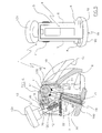
- Fig. 1 shows a schematised perspective view of the device according to the finding during the mounting of the tyre onto the rim.
- Fig. 2 illustrates a side view of the finding.
- Fig. 3 illustrates the section III-III of Fig. 2.
- Fig. 4 illustrates the section IV-IV of Fig. 3.
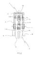
- Fig. 5 illustrates a front view of the finding.
- Fig. 6 illustrates a partially sectioned plan view of the finding.
- the rim 1 is supported and locked by a normal device 3, of a tyre-dismounting machine that is not illustrated.
- the suitable tool 4 Fixed onto the bead-stopping edge 100 of the rim 1 is the suitable tool 4 that has the function of making the insertion of the bead 200 of the tyre 2 inside the bead-stopping edge 100 of the rim 1 easier by directing it towards the channel of the rim itself.
- the tool 4 (Figs. 2, 3 and 4) comprises an outer body 5 consisting of two identical plates 6 joined together by a shaped element 7. Below each plate 6 a tooth 8 is provided, fixed canti-levered and projecting in front of the plates 6 themselves. The two teeth 8 make a fixed jaw with which the tool 4 is provided.
- a second body 9 is received the front portion of which sticks out from the two plates 6 and defines a mobile jaw 10 suitable for being brought towards and/or away from the two teeth 8 that constitute the fixed jaw.
- Said second body 9 is fixedly connected to the plates 6 thanks to a pin 11 so as to be able to rotate with respect to the plates.
- the body 9 has a fork 90 that receives a second pin 12, which has a threaded central hole 120 with which the actuation means 13 are associated that allow the rotation of the body 9 with respect to the outer body 5.
- Said actuation means 13 comprise a screw 130 that is slotted into a hole 70, of the element 7 that joins the two plates 6, and the upper free end of which carries a manoeuvring handle 131.
- the lower end of the screw 130 is threaded and screwed into the matching threaded hole 120 of the pin 12.
- the body 9 also has a recess 91 that is open on top and that receives a spring 15 that is compressed between the bottom of the recess 91 and the lower surface of the element 7.
- the function of the spring 15 is to keep the threads of the hole 120 of the pin 12 always in contact against the threads of the screw 130. Said spring 15 is always kept in the correct position by a grain 16 screwed into a threaded hole of the element 7 and the lower end of which is slotted between the spirals of the spring 15 itself.
- the body 9 has, at the pin 11, a through opening 92 in which a shaft 17 is received.
- the shaft 17 has a cylindrical upper portion 170 that is slotted onto the pin 11 with the interposition of a cage of rollers 18.
- the shaft 17 has, on the other hand, a threaded portion 171 onto which a base 19 is screwed.
- the base 19 comprises a discoidal lower portion 190 arranged below the plates 6 and a threaded upper band 191 that is screwed onto the shaft 17.
- the base 19 is screwed onto the shaft 17 it is possible to adjust its position and therefore the intensity of the force with which the discoidal portion 190 of the base 19 acts on the sidewall of the tyre 2. For this purpose indeed it is sufficient to unscrew or screw the base 19 onto the shaft 17.
- the shaft 17 can oscillate between two extreme positions delimited by two limit switch pins 20 and 21.
- the shaft 17 is kept rested against the pin 20 thanks to the action of a traction spring 22 one end of which is fixedly connected to the element 7 and the other end of which is restrained by the shaft 17 through a split pin 23 (Fig. 4).
- the rim 1 is made to rotate by actuating the tyre-dismounting machine and simultaneously the tool that takes care of pressing on the sidewall of the tyre 2.
- the base 19 oscillates towards the axis of the rim from the initial rest position, in which the shaft 17 rest on the pin 20, to the advanced position in which the shaft 17 rests on the pin 21.
- This oscillation which is gradual during the rotation of the rim, makes the bead of the tyre 2 easier to direct in the direction of the bead-stopping edge 100 of the rim 1 allowing it to be inserted below the edge 100 itself and inside the channel of the rim.
Landscapes
- Engineering & Computer Science (AREA)
- Mechanical Engineering (AREA)
- Tires In General (AREA)
Applications Claiming Priority (1)
| Application Number | Priority Date | Filing Date | Title |
|---|---|---|---|
| IT000016U ITRE20050016U1 (it) | 2005-05-17 | 2005-05-17 | Attrezzo perfezionato per agevolare il montaggio del pneumatico sul cerchione |
Publications (2)
| Publication Number | Publication Date |
|---|---|
| EP1724128A1 true EP1724128A1 (de) | 2006-11-22 |
| EP1724128B1 EP1724128B1 (de) | 2008-04-30 |
Family
ID=36699221
Family Applications (1)
| Application Number | Title | Priority Date | Filing Date |
|---|---|---|---|
| EP06075619A Expired - Lifetime EP1724128B1 (de) | 2005-05-17 | 2006-03-17 | Werkzeug für die Montage eines Reifens auf eine Felge |
Country Status (6)
| Country | Link |
|---|---|
| US (1) | US7513288B2 (de) |
| EP (1) | EP1724128B1 (de) |
| JP (1) | JP2006321476A (de) |
| DE (1) | DE602006001030T2 (de) |
| ES (1) | ES2306358T3 (de) |
| IT (1) | ITRE20050016U1 (de) |
Cited By (2)
| Publication number | Priority date | Publication date | Assignee | Title |
|---|---|---|---|---|
| EP1967392A1 (de) | 2007-03-09 | 2008-09-10 | Robert Bosch GmbH | Vorrichtung zum Montieren eines Reifens auf eine Radfelge |
| ITBO20090727A1 (it) * | 2009-11-05 | 2011-05-06 | Corghi Spa | Utensile, apparecchiatura e metodo per il montaggio di pneumatici su rispettivi cerchioni. |
Families Citing this family (7)
| Publication number | Priority date | Publication date | Assignee | Title |
|---|---|---|---|---|
| US8636048B2 (en) | 2008-05-29 | 2014-01-28 | James R. Carawan | Tire run-flat removal and installation machine |
| US8136567B2 (en) * | 2009-11-24 | 2012-03-20 | Aymar Brandon P | Car tire attachment mechanism |
| USD636003S1 (en) * | 2010-08-16 | 2011-04-12 | Hunter Engineering Company | Vehicle wheel target mount assembly |
| US9550278B2 (en) | 2011-08-10 | 2017-01-24 | Bosch Automotive Service Solutions Inc. | Tire beading locking tool and method for making same |
| US9873297B2 (en) * | 2014-02-27 | 2018-01-23 | Timothy Voegeli | Tubeless tire rim clamp assembly |
| US9333819B1 (en) * | 2015-12-21 | 2016-05-10 | BeadBuster LLC | Tire-wheel separation tool |
| IT202300011469A1 (it) | 2023-06-06 | 2024-12-06 | Nexion Spa | Pinza di ausilio a operazioni di assistenza ad una ruota di un veicolo e metodo per utilizzarla |
Citations (5)
| Publication number | Priority date | Publication date | Assignee | Title |
|---|---|---|---|---|
| GB185405A (en) * | 1921-08-30 | 1922-11-30 | Bergougnan Soc Gen Ets | Improvements in or relating to tyre levers |
| US4589462A (en) * | 1983-01-03 | 1986-05-20 | John Giles | Tire bead breaker tool |
| US4913770A (en) * | 1987-04-15 | 1990-04-03 | Freezone Pty Ltd | Tire bead breaker |
| US4993467A (en) * | 1989-11-06 | 1991-02-19 | Raymond Stavinoha | Tire bead tool |
| US6269861B1 (en) * | 2000-02-29 | 2001-08-07 | Loi V. Tran | Tire removal and installation tool |
Family Cites Families (17)
| Publication number | Priority date | Publication date | Assignee | Title |
|---|---|---|---|---|
| US1507208A (en) * | 1923-01-19 | 1924-09-02 | Schlenker Oscar Charles | Tire remover |
| US2314127A (en) * | 1942-03-21 | 1943-03-16 | George F Colley | Tire tool |
| US2520330A (en) * | 1947-04-01 | 1950-08-29 | Keith L Northrup | Tire loosening tool |
| US2581086A (en) * | 1948-09-07 | 1952-01-01 | Eli E Edenfield | Pivotally supported tire bead forcing device |
| US2606602A (en) * | 1950-05-25 | 1952-08-12 | Anthony B Manupello | Pneumatic tire bead loosening tool |
| US2900016A (en) * | 1955-11-09 | 1959-08-18 | Goodyear Tire & Rubber | Rim flange supported tire removing tool |
| US2901029A (en) * | 1957-01-14 | 1959-08-25 | John B Mraz | Rim clamping, tire-bead-breaking tool |
| US3240252A (en) * | 1964-04-09 | 1966-03-15 | Bishman Mfg Company | Tire removal tool |
| US3253640A (en) * | 1964-05-11 | 1966-05-31 | William D Paulauskas | Tire tool |
| US3771580A (en) * | 1972-08-21 | 1973-11-13 | C Branick | Earth mover tire bead breaker |
| US4787433A (en) * | 1986-10-31 | 1988-11-29 | Thomas Charles M | Bead breaking device for tractor tires |
| USRE33892E (en) * | 1987-04-15 | 1992-04-21 | Freezone Pty Ltd | Tire bead breaker |
| US4785865A (en) * | 1987-06-24 | 1988-11-22 | Folstad Lowell C | Mechanical device for releasing tire beads from wheel rims |
| DE3726409A1 (de) * | 1987-08-07 | 1989-02-16 | Hofmann Werkstatt Technik | Demontiervorrichtung fuer einen an einer radfelge befestigten reifen |
| IT1319467B1 (it) | 2000-05-22 | 2003-10-10 | Corghi Spa | Dispositivo di bloccaggio del cerchione per macchine smontagomme |
| IT1319468B1 (it) * | 2000-05-22 | 2003-10-10 | Corghi Spa | Dispositivo stallonatore automatico per macchine smontagomme, emacchine smontagomme cosi' attrezzate |
| ITRE20020004U1 (it) | 2002-02-22 | 2003-08-22 | Corghi Spa | Attrezzo per agevolare il montaggio del pneumatico sul cerchione |
-
2005
- 2005-05-17 IT IT000016U patent/ITRE20050016U1/it unknown
-
2006
- 2006-03-17 DE DE602006001030T patent/DE602006001030T2/de not_active Expired - Lifetime
- 2006-03-17 EP EP06075619A patent/EP1724128B1/de not_active Expired - Lifetime
- 2006-03-17 ES ES06075619T patent/ES2306358T3/es not_active Expired - Lifetime
- 2006-03-28 US US11/390,353 patent/US7513288B2/en not_active Expired - Fee Related
- 2006-05-10 JP JP2006131872A patent/JP2006321476A/ja active Pending
Patent Citations (5)
| Publication number | Priority date | Publication date | Assignee | Title |
|---|---|---|---|---|
| GB185405A (en) * | 1921-08-30 | 1922-11-30 | Bergougnan Soc Gen Ets | Improvements in or relating to tyre levers |
| US4589462A (en) * | 1983-01-03 | 1986-05-20 | John Giles | Tire bead breaker tool |
| US4913770A (en) * | 1987-04-15 | 1990-04-03 | Freezone Pty Ltd | Tire bead breaker |
| US4993467A (en) * | 1989-11-06 | 1991-02-19 | Raymond Stavinoha | Tire bead tool |
| US6269861B1 (en) * | 2000-02-29 | 2001-08-07 | Loi V. Tran | Tire removal and installation tool |
Cited By (2)
| Publication number | Priority date | Publication date | Assignee | Title |
|---|---|---|---|---|
| EP1967392A1 (de) | 2007-03-09 | 2008-09-10 | Robert Bosch GmbH | Vorrichtung zum Montieren eines Reifens auf eine Radfelge |
| ITBO20090727A1 (it) * | 2009-11-05 | 2011-05-06 | Corghi Spa | Utensile, apparecchiatura e metodo per il montaggio di pneumatici su rispettivi cerchioni. |
Also Published As
| Publication number | Publication date |
|---|---|
| JP2006321476A (ja) | 2006-11-30 |
| EP1724128B1 (de) | 2008-04-30 |
| ITRE20050016U1 (it) | 2006-11-18 |
| US20060260763A1 (en) | 2006-11-23 |
| ES2306358T3 (es) | 2008-11-01 |
| DE602006001030D1 (de) | 2008-06-12 |
| US7513288B2 (en) | 2009-04-07 |
| DE602006001030T2 (de) | 2008-07-31 |
Similar Documents
| Publication | Publication Date | Title |
|---|---|---|
| EP1724128B1 (de) | Werkzeug für die Montage eines Reifens auf eine Felge | |
| US9114675B2 (en) | Bead breaking unit for tyre changing machines | |
| US8657306B2 (en) | Lifting machine base assembly for a machine tool | |
| US4157594A (en) | Roller chain plier | |
| US20070144681A1 (en) | Tire changing machine | |
| EP1157860A2 (de) | Reifenabdrückvorrichtung für ein Raddemontiergerät, und Raddemontiergerät mit einer solchen Vorrichtung | |
| EP1674305A3 (de) | Reifenabnahmewerkzeug | |
| US2569242A (en) | Tire lifter | |
| EP2796302B1 (de) | Reifenwulstabdrückvorrichtung für Reifenwechselmaschinen | |
| US7946016B2 (en) | Method and machine for removing a tyre fitted with a rigid inner run-flat ring | |
| US7156141B1 (en) | Tire demounting tool | |
| EP1625954A3 (de) | Reifendemontiervorrichtung mit einem einzigen Multifunktionswerkzeug | |
| JP2000225819A (ja) | 特殊タイヤ取付け・取外し用機械 | |
| JP4551497B2 (ja) | タイヤ脱着補助具 | |
| EP1329342A1 (de) | Verbesserte Reifenwechselvorrichtung | |
| US7237465B2 (en) | Operation mechanism for pressing board of electric paper cutters | |
| CN219425493U (zh) | 一种加强板冲压辅助落料机构 | |
| US1124316A (en) | Jack. | |
| BE1016805A3 (de) | ||
| CN211031216U (zh) | 一种轮胎胎面字模压印机构 | |
| EP1717064B1 (de) | Werkzeug für die Montage / Demontage von Fahrzeugreifen | |
| JP5026476B2 (ja) | タイヤ着脱機に装着されるビード落し装置 | |
| CA2712926A1 (en) | Sanding machine with clamping mechanism | |
| CN216966053U (zh) | 一种圆形薄壁零件铆压装置 | |
| KR20150144374A (ko) | 타이어 탈부착장치 |
Legal Events
| Date | Code | Title | Description |
|---|---|---|---|
| PUAI | Public reference made under article 153(3) epc to a published international application that has entered the european phase |
Free format text: ORIGINAL CODE: 0009012 |
|
| AK | Designated contracting states |
Kind code of ref document: A1 Designated state(s): AT BE BG CH CY CZ DE DK EE ES FI FR GB GR HU IE IS IT LI LT LU LV MC NL PL PT RO SE SI SK TR |
|
| AX | Request for extension of the european patent |
Extension state: AL BA HR MK YU |
|
| 17P | Request for examination filed |
Effective date: 20070427 |
|
| GRAP | Despatch of communication of intention to grant a patent |
Free format text: ORIGINAL CODE: EPIDOSNIGR1 |
|
| AKX | Designation fees paid |
Designated state(s): DE ES FR IT |
|
| RIN1 | Information on inventor provided before grant (corrected) |
Inventor name: CORGHI, REMO |
|
| GRAS | Grant fee paid |
Free format text: ORIGINAL CODE: EPIDOSNIGR3 |
|
| GRAA | (expected) grant |
Free format text: ORIGINAL CODE: 0009210 |
|
| AK | Designated contracting states |
Kind code of ref document: B1 Designated state(s): DE ES FR IT |
|
| REF | Corresponds to: |
Ref document number: 602006001030 Country of ref document: DE Date of ref document: 20080612 Kind code of ref document: P |
|
| REG | Reference to a national code |
Ref country code: ES Ref legal event code: FG2A Ref document number: 2306358 Country of ref document: ES Kind code of ref document: T3 |
|
| ET | Fr: translation filed | ||
| PLBE | No opposition filed within time limit |
Free format text: ORIGINAL CODE: 0009261 |
|
| STAA | Information on the status of an ep patent application or granted ep patent |
Free format text: STATUS: NO OPPOSITION FILED WITHIN TIME LIMIT |
|
| 26N | No opposition filed |
Effective date: 20090202 |
|
| PGFP | Annual fee paid to national office [announced via postgrant information from national office to epo] |
Ref country code: IT Payment date: 20110326 Year of fee payment: 6 |
|
| PGFP | Annual fee paid to national office [announced via postgrant information from national office to epo] |
Ref country code: FR Payment date: 20110414 Year of fee payment: 6 Ref country code: ES Payment date: 20110428 Year of fee payment: 6 |
|
| PGFP | Annual fee paid to national office [announced via postgrant information from national office to epo] |
Ref country code: DE Payment date: 20110526 Year of fee payment: 6 |
|
| REG | Reference to a national code |
Ref country code: FR Ref legal event code: ST Effective date: 20121130 |
|
| REG | Reference to a national code |
Ref country code: DE Ref legal event code: R119 Ref document number: 602006001030 Country of ref document: DE Effective date: 20121002 |
|
| PG25 | Lapsed in a contracting state [announced via postgrant information from national office to epo] |
Ref country code: FR Free format text: LAPSE BECAUSE OF NON-PAYMENT OF DUE FEES Effective date: 20120402 |
|
| PG25 | Lapsed in a contracting state [announced via postgrant information from national office to epo] |
Ref country code: IT Free format text: LAPSE BECAUSE OF NON-PAYMENT OF DUE FEES Effective date: 20120317 |
|
| REG | Reference to a national code |
Ref country code: ES Ref legal event code: FD2A Effective date: 20130710 |
|
| PG25 | Lapsed in a contracting state [announced via postgrant information from national office to epo] |
Ref country code: ES Free format text: LAPSE BECAUSE OF NON-PAYMENT OF DUE FEES Effective date: 20120318 |
|
| PG25 | Lapsed in a contracting state [announced via postgrant information from national office to epo] |
Ref country code: DE Free format text: LAPSE BECAUSE OF NON-PAYMENT OF DUE FEES Effective date: 20121002 |