EP2796302B1 - Reifenwulstabdrückvorrichtung für Reifenwechselmaschinen - Google Patents
Reifenwulstabdrückvorrichtung für Reifenwechselmaschinen Download PDFInfo
- Publication number
- EP2796302B1 EP2796302B1 EP14162897.4A EP14162897A EP2796302B1 EP 2796302 B1 EP2796302 B1 EP 2796302B1 EP 14162897 A EP14162897 A EP 14162897A EP 2796302 B1 EP2796302 B1 EP 2796302B1
- Authority
- EP
- European Patent Office
- Prior art keywords
- bead breaking
- tyre
- arm
- bead
- breaking unit
- Prior art date
- Legal status (The legal status is an assumption and is not a legal conclusion. Google has not performed a legal analysis and makes no representation as to the accuracy of the status listed.)
- Active
Links
Images




Classifications
-
- B—PERFORMING OPERATIONS; TRANSPORTING
- B60—VEHICLES IN GENERAL
- B60C—VEHICLE TYRES; TYRE INFLATION; TYRE CHANGING; CONNECTING VALVES TO INFLATABLE ELASTIC BODIES IN GENERAL; DEVICES OR ARRANGEMENTS RELATED TO TYRES
- B60C25/00—Apparatus or tools adapted for mounting, removing or inspecting tyres
- B60C25/01—Apparatus or tools adapted for mounting, removing or inspecting tyres for removing tyres from or mounting tyres on wheels
- B60C25/05—Machines
- B60C25/125—Machines for only breaking the beads
- B60C25/13—Machines for only breaking the beads acting axially on a part of the bead or side wall only at localised regions of the bead or side wall
-
- B—PERFORMING OPERATIONS; TRANSPORTING
- B60—VEHICLES IN GENERAL
- B60C—VEHICLE TYRES; TYRE INFLATION; TYRE CHANGING; CONNECTING VALVES TO INFLATABLE ELASTIC BODIES IN GENERAL; DEVICES OR ARRANGEMENTS RELATED TO TYRES
- B60C25/00—Apparatus or tools adapted for mounting, removing or inspecting tyres
- B60C25/01—Apparatus or tools adapted for mounting, removing or inspecting tyres for removing tyres from or mounting tyres on wheels
- B60C25/05—Machines
- B60C25/132—Machines for removing and mounting tyres
- B60C25/135—Machines for removing and mounting tyres having a tyre support or a tool, movable along wheel axis
- B60C25/138—Machines for removing and mounting tyres having a tyre support or a tool, movable along wheel axis with rotary motion of tool or tyre support
Definitions
- the present invention relates to a bead breaking unit for tyre changing machines.
- Tyre changing machines are commonly used for fitting/removing vehicle wheel tyres to/from respective rims.
- This operation is performed by means of a suitable bead breaking unit, normally present on the tyre changing machine itself.
- Bead breaking units of known type comprise an arm with a first extremity hinged to the bed of the tyre changing machine according to a substantially vertical axis and a second extremity having a bead breaking tool, otherwise known as blade.
- This resting element has a resting surface, otherwise known as pad, which is made of suitable material, and usually knurled in such a way as to increase the friction coefficient with the wheel.
- the bead breaking units of known type generally comprise a linear actuator of the type, e.g., of a fluid actuator cylinder for moving the arm.
- an operator suitably positions the portion of the wheel to undergo bead breaking in correspondence to the pad and positions the blade in contact with a section of the tyre bead.
- Bead breaking units are also known having a suitable device for positioning the bead breaking blade on two or more predefined angular positions with respect to the bead resting surface.
- the inclination of the blade can be set according to the particular type of tyre to undergo bead breaking.
- Bead breaking units are in fact known with an operating head having two different blades, arranged with different angular positions, wherein the operating head can be rotated to position each of the two blades alternately in the work position.
- bead breaking units having a tilting blade, suitable for varying its inclination, in contrast to the action of one or more springs, during the pressure applied on a tyre.
- tilting can be locked by means of a suitable pin lock.
- bead breaking units of known type are susceptible to upgrading, aimed in particular at achieving an optimum bead breaking according to the particular type of tyre to undergo bead breaking.
- the main aim of the present invention is to provide a bead breaking unit for tyre changing machines or the like which allows an optimum bead breaking depending on the particular type of tyre to undergo bead breaking.
- WO 2008/132567 A1 discloses a pressing apparatus, suitable for pressing the sides of tyres, comprising a supporting element, a pressing disc freely mounted rotating on an arm which can be fitted to the supporting element, wherein the arm is fitted to the supporting element in a way that can be chosen between a fixed configuration and an oscillating configuration.
- Document EP 1 607 247 A1 discloses a bead breaker device comprising an arm able to slide horizontally along a sliding axis, an orientable bead breaker tool associated with an end of the arm and suitable for breaking the bead of a tire of a wheel removably fixed onto rotary support and locking means of the rim, actuation means suitable for orienting the tool between a first thrusting configuration and a second penetration configuration, where the actuation means comprise a thrusting body and elastic means cooperating with the tool, wherein the thrusting body is able to be actuated between a first extension position in contrast to the action of the elastic means and a second release position in which the force exerted by said elastic means prevails.
- Another object of the present invention is to provide a bead breaking unit for tyre changing machines which permits a simpler and faster adjustment of blade inclination and/or tilting.
- Another object of the present invention is to provide a bead breaking unit for tyre changing machines which allows overcoming the mentioned drawbacks of the state of the art within the ambit of a simple, rational, easy and effective to use as well as low cost solution.
- a bead breaking unit which can be fitted on tyre changing machines of known type and usable for the first detachment of the bead of the tyre from the respective rim of a wheel, before the fitting/removing operation of the tyre itself.
- the bead breaking unit 1 can be fitted e.g. on a conventional tyre changing machine M of the type shown in figure 1 .
- the bead breaking unit 1 comprises an arm 2 with a first extremity hinged to a supporting structure 3 and revolving around a substantially vertical hinging axis, and a second extremity having a bead breaking tool 4.
- the bead breaking tool 4 can be composed, e.g., of a conventional bead breaking blade.
- the supporting structure 3 can be fixed, e.g., to the bed B of the tyre changing machine M.
- the arm 2 is suitable for oscillating between a disengaging position, wherein the blade 4 is substantially spaced apart from the resting surface 5, and an operating position, wherein the blade 4 is placed substantially close to the resting surface 5 and is suitable for engaging on one side of the tyre of a wheel to undergo bead breaking.
- the bead breaking unit 1 also comprises movement means 6, composed e.g. of a linear actuator, operatively associated with the arm 2 and suitable for moving it from the disengaging position to the operating position.
- movement means 6, composed e.g. of a linear actuator, operatively associated with the arm 2 and suitable for moving it from the disengaging position to the operating position.
- the bead breaking unit 1 also has tilting means for tilting the blade 4, altogether indicated in the illustrations by the reference 7, suitable for allowing the partial rotation of the blade 4 when this is engaged on the tyre.
- the tilting means 7 comprise a sustaining element 8 which supports the blade 4 and which is associated with the free extremity of the arm 2 revolving around a tilting axis X.
- the sustaining element 8 is composed of a pair of integral plates, parallel and distanced from each other, hinged at the free extremity of the arm 2 by means of a pin 9, in correspondence to the tilting axis X.
- the tilting means 7 also comprise at least a flexible element 10, preferably composed of a spring, placed between a portion of the sustaining element 8 and a portion of the arm 2 and suitable for operating in contrast to the rotation of the sustaining element itself when the blade 4 is engaged and applies a pressure on the side of a tyre to undergo bead breaking.
- a flexible element 10 preferably composed of a spring
- the partial rotation of the sustaining element 8 in contrast to the spring 10 is shown by way of example in the figure 6 .
- the bead breaking unit 1 comprises adjustment means 11 suitable for adjusting the angular position of the blade 4 and activation/deactivation means 12 suitable for activating/deactivating the tilting means 7.
- the adjustment of the angular position of the blade 4 and the activation/deactivation of tilting can be carried out according to the dimensions and/or the hardness and/or the particular type of tyre to undergo bead breaking.
- a reduced angle of incidence generally close to 21°
- a pressure along a narrower and more defined portion of the tyre in the proximity of the edge of the rim ( figures 4 and 5 ).
- the adjustment means 11 are suitable for varying the angle of incidence of the blade 4 with respect to the resting surface 5.
- the adjustment means 11 comprise a first operating element 13, having a grip, operatively associated with the blade 4 and which can be operated to vary the angular position of the blade itself.
- the first operating element 13 can consist, e.g., of a first grip knob.
- the first knob 13 is associated revolving around the sustaining element 8 and the adjustment means 11 comprise transformation means for transforming the rotary motion of the first knob 13 into a rotary motion of the blade 4.
- such means of transformation comprise a first eccentric element 14 having the first knob 13 and revolving around a first rotation axis R1.
- the transformation means of the rotary motion of the first knob 13 into the rotary motion of the blade 4 are composed of a crank mechanism, where the first eccentric element 14 is composed of a first pin which extends between the plates of the sustaining element 8.
- the first pin 14 besides being eccentric and revolving around the first rotation axis R1, is associated translatable with the sustaining element 8 along at least one direction of translation.
- the sustaining element 8 has guide means 15 suitable for guiding the first pin 14 along a direction of translation.
- the guide means 15 are composed of a pair of first elongated slots made in correspondence to respective portions of each of the plates of the sustaining element 8.
- the first knob 13 is fastened to the first support 16 associated with the upper plate of the sustaining element 8.
- a supporting element 17 of the blade 4 with a substantially elongated shape, has a first extremity associated revolving with the arm 2, in correspondence to a second rotation axis R2, and a second extremity having a housing suitable for housing the first pin 14 to measure and rotatable.
- the rotation of the first knob 13 involves the rotation of the first pin 14 around the first rotation axis R1 and, at the same time, the translation of the first supports 16 inside the respective first slots 15, thereby allowing the adjustment of the angular position of the supporting element 17 and, consequently, the adjustment of the angular position of the blade 4.
- the activation/deactivation means 12 comprise a second operating element 18 operatively associated with the tilting means 7 and which can be operated to activate/deactivate the tilting means themselves.
- the second operating element 18 is composed of a second grip knob.
- the activation/deactivation means 12 comprise at least a second eccentric element 19 having a second knob 18, revolving around a third rotation axis R3 between a release position, wherein the tilting means 7 are activated, and a locking position, wherein the tilting means 7 are deactivated.
- the second eccentric element 19 when it is in the locking position, is suitable for engaging in correspondence to a respective reference portion of the sustaining element 8 to prevent the sustaining element itself from rotating free around the tilting axis X.
- the activation/deactivation means 12 are composed of a crank mechanism, where the second eccentric element 19 is composed of a pair of second supports suitable for supporting, in correspondence to the opposite extremities, a second pin 20 which extends between the plates of the sustaining element 8.
- the second pin 20 is axially revolving around the third rotation axis R3 and the second supports 19 are housed inside the respective second slots 21 made in correspondence to respective portions on each of the plates of the sustaining element 8.
- the second knob 18 is fastened to the second support 19 associated with the upper plate of the sustaining element 8.
- each of them is suitable for engaging in correspondence to a respective section of the inner edge of each of the slots 21, to prevent the sustaining element 8 from rotating free around the tilting axis X.
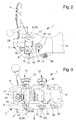
- FIG 7 shows the bead breaking unit 1 in an idle position, with the activation/deactivation means 12 in the release position.
- the figure 8 instead shows the bead breaking unit 1 in a tilted position due to the action of the tilting means, with the activation/deactivation means 12 in the release position.
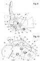
- FIGS 9 and 10 show the bead breaking unit 1 with the activationldeactivation means 12 in the locking position.
- the figure 11 shows, in detail, possible and preferred conformations of the first, the second and the third slots 15, 21 and 23 made on the plates of the sustaining element 8.
- the stroke of the sustaining element 8 during the rotation around the tilting axis X is restricted by the action of a third pin 22, fastened in correspondence to a lower portion of the arm 2, fitted sliding inside a third slot 23, elongated and curvilinear, made along a portion of the lower plate of the sustaining element 8, and suitable for engaging in correspondence to the edges of the opposite extremities of the third slot 23.
- the bead breaking unit 1 has at least a joint 24, placed between the supporting element 17 and the blade 4, suitable for permitting further variations of the orientation of the blade itself.
Landscapes
- Engineering & Computer Science (AREA)
- Mechanical Engineering (AREA)
- Separation, Recovery Or Treatment Of Waste Materials Containing Plastics (AREA)
- Preliminary Treatment Of Fibers (AREA)
- Breakers (AREA)
- Emergency Protection Circuit Devices (AREA)
- Milling, Broaching, Filing, Reaming, And Others (AREA)
- Tires In General (AREA)
- Crushing And Pulverization Processes (AREA)
- Tyre Moulding (AREA)
- Moulds For Moulding Plastics Or The Like (AREA)
Claims (12)
- Abdrückeinheit (1) für Reifenwechselmaschinen, umfassend mindestens einen Arm (2), der drehbar mit einer Haltestruktur (3) verbunden ist, mindestens ein Abdrückwerkzeug (4), das mit dem Arm (2) verbunden ist, mindestens eine Aufliegefläche (5) eines einem Abdrücken zu unterziehenden Reifens eines Rades, Bewegungsmittel (6), das operativ mit dem Arm (2) verbunden ist und sich zum Bewegen des Arms (2) aus einer ausgerückten Position eignet, wobei das Abdrückwerkzeug (4) im Wesentlichen vom Reifen in eine Betriebsposition wegbewegt wird, wobei das Abdrückwerkzeug (4) sich zum Eingreifen in den Reifen eignet, der Arm (2) Neigungsmittel (7) des Abdrückwerkzeugs (4) hat, das sich dafür eignet, die Teilrotation des Abdrückwerkzeugs (4) zu ermöglichen, wenn es in den Reifen und Aktivierungs-/Deaktivierungsmittel (12) der Neigungsmittel (7) eingreift,
dadurch gekennzeichnet, dass sie
Einstellmittel (11) zum Variieren des Einfallswinkels des Abdrückwerkzeugs (4) in Bezug auf die Aufliegefläche (5) entsprechend den Abmessungen und/oder der Härte und/oder des speziellen Typs von Reifen umfasst, die sich einem Abdrücken unterziehen. - Abdrückeinheit (1) nach Anspruch 1, dadurch gekennzeichnet, dass die Einstellmittel (11) mindestens ein erstes Betriebselement (13) umfassen, das operativ mit dem Abdrückwerkzeug (4) verbunden ist und das betrieben werden kann, um die Winkelposition des Abdrückwerkzeugs (4) zu variieren.
- Abdrückeinheit (1) nach Anspruch 2, dadurch gekennzeichnet, dass das erste Betriebselement (13) drehbar mit dem Arm (2) verbunden ist, und die Einstellmittel (11) Transformationsmittel (14, 15, 16, 17) zum Transformieren der Drehbewegung des Betriebselementes in eine Drehbewegung des Abdrückwerkzeugs (4) umfassen.
- Abdrückeinheit (1) nach Anspruch 3, dadurch gekennzeichnet, dass die Transformationsmittel (14, 15, 16, 17) mindestens ein exzentrisches Element (14) umfassen, das das erste Betriebselement (13) umfasst und um eine erste Rotationsachse (R1) drehbar ist.
- Abdrückeinheit (1) nach Anspruch 4, dadurch gekennzeichnet, dass die Transformationsmittel (14, 15, 16, 17) mindestens ein Halteelement (17) des Abdrückwerkzeugs (4) umfassen, mit einer im Wesentlichen gestreckten Gestalt, mit einer ersten Extremität, die drehbar mit dem Arm (2) verbunden ist in Übereinstimmung mit einer zweiten Rotationsachse, und mit einer zweiten Extremität, die ein Gehäuse hat, das sich dafür eignet, das erste exzentrische Element (14) drehbar aufzunehmen.
- Abdrückeinheit (1) nach einem der Ansprüche 4 und 5, dadurch gekennzeichnet, dass das erste exzentrische Element (14) entlang mindestens einer Verschiebungsrichtung verschiebbar mit dem Arm (2) verbunden ist.
- Abdrückeinheit (1) nach Anspruch 6, dadurch gekennzeichnet, dass sie Führungsmittel (15) zum Führen der Verschiebung des ersten exzentrischen Elementes (14) entlang der Verschiebungsrichtung umfasst.
- Abdrückeinheit (1) nach einem der vorherigen Ansprüche, dadurch gekennzeichnet, dass die Neigungsmittel (7) mindestens ein flexibles Element (10) umfassen, das zwischen dem Abdrückwerkzeug (4) und dem Arm (2) platziert ist und sich zum Betreiben im Gegensatz zur Rotation des Abdrückwerkzeugs (4) eignet, wenn es im Eingriff mit dem Reifen ist.
- Abdrückeinheit (1) nach einem der vorherigen Ansprüche, dadurch gekennzeichnet, dass die Aktivierungs-/Deaktivierungsmittel (12) mindestens ein zweites Betriebselement (18) umfassen, das operativ mit den Neigungsmitteln (7) verbunden ist und das betrieben werden kann, um die Neigungsmittel (7) zu aktivieren/deaktivieren.
- Abdrückeinheit (1) nach Anspruch 9, dadurch gekennzeichnet, dass die Aktivierungs-/Deaktivierungsmittel (12) mindestens ein zweites exzentrisches Element (19) umfassen, das ein zweites Betriebselement (18) hat, das um eine dritte Rotationsachse (R3) zwischen einer Freigabeposition, in der die Neigungsmittel (7) aktiviert sind, und einer Sperrposition, in der die Neigungsmittel (7) deaktiviert sind, drehbar ist.
- Abdrückeinheit (1) nach Anspruch 10, dadurch gekennzeichnet, dass die Neigungsmittel (7) mindestens ein stützendes Element (8) umfassen, das um eine Neigungsachse (X) drehbar ist und sich dazu eignet, das Abdrückwerkzeug (4) zu stützen, und dadurch, dass beim Positionieren in der Sperrposition das zweite exzentrische Element (19) sich für den Eingriff in Übereinstimmung mit einem entsprechenden Referenzteil des tragenden Elementes (8) eignet, um zu verhindern, dass das tragende Element (8) frei um die Neigungsachse (X) rotiert.
- Abdrückeinheit (1) nach Anspruch 11, dadurch gekennzeichnet, dass das tragende Element (8) mindestens einen länglichen Schlitz (21) zum Aufnehmen des zweiten exzentrischen Elementes (19) umfasst, wobei der Referenzteil aus mindestens einem Abschnitt der Innenkante des länglichen Schlitzes besteht.
Applications Claiming Priority (1)
| Application Number | Priority Date | Filing Date | Title |
|---|---|---|---|
| IT000110A ITMO20130110A1 (it) | 2013-04-23 | 2013-04-23 | Gruppo stallonatore per macchine smontagomme o simili |
Publications (2)
| Publication Number | Publication Date |
|---|---|
| EP2796302A1 EP2796302A1 (de) | 2014-10-29 |
| EP2796302B1 true EP2796302B1 (de) | 2017-06-14 |
Family
ID=48703703
Family Applications (1)
| Application Number | Title | Priority Date | Filing Date |
|---|---|---|---|
| EP14162897.4A Active EP2796302B1 (de) | 2013-04-23 | 2014-03-31 | Reifenwulstabdrückvorrichtung für Reifenwechselmaschinen |
Country Status (5)
| Country | Link |
|---|---|
| US (1) | US20140311682A1 (de) |
| EP (1) | EP2796302B1 (de) |
| JP (1) | JP2014213850A (de) |
| CN (1) | CN104118286B (de) |
| IT (1) | ITMO20130110A1 (de) |
Families Citing this family (6)
| Publication number | Priority date | Publication date | Assignee | Title |
|---|---|---|---|---|
| USD764556S1 (en) * | 2014-03-14 | 2016-08-23 | Sicam S.R.L. | Tire fitting machine |
| US9873298B2 (en) * | 2014-05-07 | 2018-01-23 | Gino Ferrari | De-beading device for tire-changing machines |
| CN108430808B (zh) | 2015-11-10 | 2020-10-16 | 斯耐普昂仪器有限公司 | 轮胎拆装机 |
| IT201900010590A1 (it) * | 2019-07-01 | 2021-01-01 | Beissbarth Gmbh | Gruppo stallonatore per macchine smontagomme |
| CN111942087A (zh) * | 2020-08-06 | 2020-11-17 | 曾鹏 | 一种省力快速撬胎设备 |
| IT202200018168A1 (it) * | 2022-09-06 | 2024-03-06 | Nexion Spa | Macchina smontagomme e metodo per utilizzare una macchina smontagomme |
Family Cites Families (14)
| Publication number | Priority date | Publication date | Assignee | Title |
|---|---|---|---|---|
| US4760871A (en) * | 1985-07-11 | 1988-08-02 | Fmc Corporation | Lower bead breaker removal and adjustment apparatus |
| US5226465A (en) * | 1991-02-19 | 1993-07-13 | Stahlgruber Otto Gruber Gmbh & Co. | Mounting device for motor vehicle tires |
| IT1258032B (it) * | 1992-02-28 | 1996-02-20 | Corghi Spa | Dispositivo stallonatore per macchine smontagomme |
| IT239331Y1 (it) * | 1995-05-23 | 2001-02-26 | Butler Eng & Marketing | Macchina smontagomme dotata di dispositivo stallonatore |
| IT1319437B1 (it) * | 2000-10-24 | 2003-10-10 | Elettromeccaniche S I C E Soc | Macchina smontagomme |
| ITRE20030095A1 (it) * | 2003-10-14 | 2005-04-15 | Corghi Spa | Dispositivo stallonatore per macchine smontagomme. |
| ITRE20040072A1 (it) * | 2004-06-15 | 2004-09-15 | Corghi Spa | Dispositivo stallonatore |
| ITMO20060274A1 (it) * | 2006-09-08 | 2008-03-09 | Giuliano Spa | Gruppo stallonatore per macchine smontagomme |
| ITMO20070144A1 (it) * | 2007-04-27 | 2008-10-28 | Gino Ferrari | "apparato pressore" |
| IT1396966B1 (it) * | 2009-12-16 | 2012-12-20 | Giuliano S P A Ora Giuliano Group S P A | Gruppo stallonatore per macchine smontagomme |
| IT1402895B1 (it) * | 2010-11-23 | 2013-09-27 | Pogliani & Rivolta S P A | Dispositivo di stallonamento di pneumatici |
| ITMO20110118A1 (it) * | 2011-05-20 | 2012-11-21 | Giuliano Group Spa | Gruppo stallonatore per macchine smontagomme |
| ITMO20110132A1 (it) * | 2011-05-24 | 2012-11-25 | Giuliano Group Spa | Gruppo stallonatore perfezionato per macchine smontagomme o simili |
| WO2015013463A1 (en) * | 2013-07-23 | 2015-01-29 | Hennessy Industries, Inc. | Tire changing machine with bead loosener arm |
-
2013
- 2013-04-23 IT IT000110A patent/ITMO20130110A1/it unknown
-
2014
- 2014-03-24 US US14/223,193 patent/US20140311682A1/en not_active Abandoned
- 2014-03-31 EP EP14162897.4A patent/EP2796302B1/de active Active
- 2014-04-02 JP JP2014076115A patent/JP2014213850A/ja active Pending
- 2014-04-23 CN CN201410165874.2A patent/CN104118286B/zh active Active
Also Published As
| Publication number | Publication date |
|---|---|
| EP2796302A1 (de) | 2014-10-29 |
| CN104118286B (zh) | 2017-01-04 |
| CN104118286A (zh) | 2014-10-29 |
| ITMO20130110A1 (it) | 2014-10-24 |
| JP2014213850A (ja) | 2014-11-17 |
| US20140311682A1 (en) | 2014-10-23 |
Similar Documents
| Publication | Publication Date | Title |
|---|---|---|
| EP2796302B1 (de) | Reifenwulstabdrückvorrichtung für Reifenwechselmaschinen | |
| EP1880876B1 (de) | Reifenwulstablösevorrichtung für Reifenwechselgeräte | |
| CN101391565B (zh) | 一种用于轮胎拆装机的胎圈分离辊头 | |
| EP2338705B1 (de) | Reifenwulstabdrückvorrichtung für Reifenwechselgeräte | |
| EP2524819B1 (de) | Wulstlösevorrichtung für Reifenwechselgeräte | |
| US9833871B2 (en) | Sander, especially for sanding curved surfaces | |
| EP2527166B1 (de) | Reifenwulstabdrückvorrichtung für Reifenwechselmaschinen | |
| US20150367224A1 (en) | Skate sharpening fixture | |
| CN107953733A (zh) | 轮胎更换机 | |
| PL1623850T3 (pl) | Maszyna do zakładania i zdejmowania opon pojazdów | |
| EP1329342A1 (de) | Verbesserte Reifenwechselvorrichtung | |
| EP1724128B1 (de) | Werkzeug für die Montage eines Reifens auf eine Felge | |
| CN113825592B (zh) | 具有制动装置的轨道式研磨机 | |
| JPH079821A (ja) | ホイールリムにタイヤを装着するための機械 | |
| CA2583085A1 (en) | Aging apparatus for aging an artificial stone | |
| WO2007086242A1 (ja) | 自動車用タイヤの表面研磨装置 | |
| KR20150105887A (ko) | 곡면형 터치 스크린 패널의 라미네이션장치 | |
| JP5026476B2 (ja) | タイヤ着脱機に装着されるビード落し装置 | |
| WO2008132567A1 (en) | Debeading apparatus | |
| EP3760457A1 (de) | Wulstabdrückvorrichtung für reifenwechselmaschinen | |
| EP3437901B1 (de) | Reifenabdrückvorrichtung | |
| JP4374412B2 (ja) | 円盤刃研削装置、位置決め手段及び円盤刃研削方法 | |
| JPH0631609A (ja) | 湾曲面を有する硝子物品の研磨装置 | |
| JP2004224289A (ja) | タイヤ着脱装置 | |
| CA2894620A1 (en) | Skate sharpening fixture |
Legal Events
| Date | Code | Title | Description |
|---|---|---|---|
| PUAI | Public reference made under article 153(3) epc to a published international application that has entered the european phase |
Free format text: ORIGINAL CODE: 0009012 |
|
| 17P | Request for examination filed |
Effective date: 20140331 |
|
| AK | Designated contracting states |
Kind code of ref document: A1 Designated state(s): AL AT BE BG CH CY CZ DE DK EE ES FI FR GB GR HR HU IE IS IT LI LT LU LV MC MK MT NL NO PL PT RO RS SE SI SK SM TR |
|
| AX | Request for extension of the european patent |
Extension state: BA ME |
|
| R17P | Request for examination filed (corrected) |
Effective date: 20150727 |
|
| RBV | Designated contracting states (corrected) |
Designated state(s): AL AT BE BG CH CY CZ DE DK EE ES FI FR GB GR HR HU IE IS IT LI LT LU LV MC MK MT NL NO PL PT RO RS SE SI SK SM TR |
|
| GRAP | Despatch of communication of intention to grant a patent |
Free format text: ORIGINAL CODE: EPIDOSNIGR1 |
|
| STAA | Information on the status of an ep patent application or granted ep patent |
Free format text: STATUS: GRANT OF PATENT IS INTENDED |
|
| INTG | Intention to grant announced |
Effective date: 20170109 |
|
| GRAS | Grant fee paid |
Free format text: ORIGINAL CODE: EPIDOSNIGR3 |
|
| GRAA | (expected) grant |
Free format text: ORIGINAL CODE: 0009210 |
|
| STAA | Information on the status of an ep patent application or granted ep patent |
Free format text: STATUS: THE PATENT HAS BEEN GRANTED |
|
| AK | Designated contracting states |
Kind code of ref document: B1 Designated state(s): AL AT BE BG CH CY CZ DE DK EE ES FI FR GB GR HR HU IE IS IT LI LT LU LV MC MK MT NL NO PL PT RO RS SE SI SK SM TR |
|
| REG | Reference to a national code |
Ref country code: GB Ref legal event code: FG4D |
|
| REG | Reference to a national code |
Ref country code: CH Ref legal event code: EP Ref country code: AT Ref legal event code: REF Ref document number: 900587 Country of ref document: AT Kind code of ref document: T Effective date: 20170615 |
|
| REG | Reference to a national code |
Ref country code: IE Ref legal event code: FG4D |
|
| REG | Reference to a national code |
Ref country code: DE Ref legal event code: R096 Ref document number: 602014010659 Country of ref document: DE |
|
| REG | Reference to a national code |
Ref country code: NL Ref legal event code: MP Effective date: 20170614 |
|
| REG | Reference to a national code |
Ref country code: LT Ref legal event code: MG4D |
|
| PG25 | Lapsed in a contracting state [announced via postgrant information from national office to epo] |
Ref country code: NO Free format text: LAPSE BECAUSE OF FAILURE TO SUBMIT A TRANSLATION OF THE DESCRIPTION OR TO PAY THE FEE WITHIN THE PRESCRIBED TIME-LIMIT Effective date: 20170914 Ref country code: HR Free format text: LAPSE BECAUSE OF FAILURE TO SUBMIT A TRANSLATION OF THE DESCRIPTION OR TO PAY THE FEE WITHIN THE PRESCRIBED TIME-LIMIT Effective date: 20170614 Ref country code: GR Free format text: LAPSE BECAUSE OF FAILURE TO SUBMIT A TRANSLATION OF THE DESCRIPTION OR TO PAY THE FEE WITHIN THE PRESCRIBED TIME-LIMIT Effective date: 20170915 Ref country code: LT Free format text: LAPSE BECAUSE OF FAILURE TO SUBMIT A TRANSLATION OF THE DESCRIPTION OR TO PAY THE FEE WITHIN THE PRESCRIBED TIME-LIMIT Effective date: 20170614 Ref country code: FI Free format text: LAPSE BECAUSE OF FAILURE TO SUBMIT A TRANSLATION OF THE DESCRIPTION OR TO PAY THE FEE WITHIN THE PRESCRIBED TIME-LIMIT Effective date: 20170614 |
|
| REG | Reference to a national code |
Ref country code: AT Ref legal event code: MK05 Ref document number: 900587 Country of ref document: AT Kind code of ref document: T Effective date: 20170614 |
|
| PG25 | Lapsed in a contracting state [announced via postgrant information from national office to epo] |
Ref country code: NL Free format text: LAPSE BECAUSE OF FAILURE TO SUBMIT A TRANSLATION OF THE DESCRIPTION OR TO PAY THE FEE WITHIN THE PRESCRIBED TIME-LIMIT Effective date: 20170614 Ref country code: BG Free format text: LAPSE BECAUSE OF FAILURE TO SUBMIT A TRANSLATION OF THE DESCRIPTION OR TO PAY THE FEE WITHIN THE PRESCRIBED TIME-LIMIT Effective date: 20170914 Ref country code: SE Free format text: LAPSE BECAUSE OF FAILURE TO SUBMIT A TRANSLATION OF THE DESCRIPTION OR TO PAY THE FEE WITHIN THE PRESCRIBED TIME-LIMIT Effective date: 20170614 Ref country code: RS Free format text: LAPSE BECAUSE OF FAILURE TO SUBMIT A TRANSLATION OF THE DESCRIPTION OR TO PAY THE FEE WITHIN THE PRESCRIBED TIME-LIMIT Effective date: 20170614 Ref country code: LV Free format text: LAPSE BECAUSE OF FAILURE TO SUBMIT A TRANSLATION OF THE DESCRIPTION OR TO PAY THE FEE WITHIN THE PRESCRIBED TIME-LIMIT Effective date: 20170614 |
|
| PG25 | Lapsed in a contracting state [announced via postgrant information from national office to epo] |
Ref country code: CZ Free format text: LAPSE BECAUSE OF FAILURE TO SUBMIT A TRANSLATION OF THE DESCRIPTION OR TO PAY THE FEE WITHIN THE PRESCRIBED TIME-LIMIT Effective date: 20170614 Ref country code: SK Free format text: LAPSE BECAUSE OF FAILURE TO SUBMIT A TRANSLATION OF THE DESCRIPTION OR TO PAY THE FEE WITHIN THE PRESCRIBED TIME-LIMIT Effective date: 20170614 Ref country code: RO Free format text: LAPSE BECAUSE OF FAILURE TO SUBMIT A TRANSLATION OF THE DESCRIPTION OR TO PAY THE FEE WITHIN THE PRESCRIBED TIME-LIMIT Effective date: 20170614 Ref country code: EE Free format text: LAPSE BECAUSE OF FAILURE TO SUBMIT A TRANSLATION OF THE DESCRIPTION OR TO PAY THE FEE WITHIN THE PRESCRIBED TIME-LIMIT Effective date: 20170614 Ref country code: AT Free format text: LAPSE BECAUSE OF FAILURE TO SUBMIT A TRANSLATION OF THE DESCRIPTION OR TO PAY THE FEE WITHIN THE PRESCRIBED TIME-LIMIT Effective date: 20170614 |
|
| PG25 | Lapsed in a contracting state [announced via postgrant information from national office to epo] |
Ref country code: SM Free format text: LAPSE BECAUSE OF FAILURE TO SUBMIT A TRANSLATION OF THE DESCRIPTION OR TO PAY THE FEE WITHIN THE PRESCRIBED TIME-LIMIT Effective date: 20170614 Ref country code: ES Free format text: LAPSE BECAUSE OF FAILURE TO SUBMIT A TRANSLATION OF THE DESCRIPTION OR TO PAY THE FEE WITHIN THE PRESCRIBED TIME-LIMIT Effective date: 20170614 Ref country code: IS Free format text: LAPSE BECAUSE OF FAILURE TO SUBMIT A TRANSLATION OF THE DESCRIPTION OR TO PAY THE FEE WITHIN THE PRESCRIBED TIME-LIMIT Effective date: 20171014 Ref country code: PL Free format text: LAPSE BECAUSE OF FAILURE TO SUBMIT A TRANSLATION OF THE DESCRIPTION OR TO PAY THE FEE WITHIN THE PRESCRIBED TIME-LIMIT Effective date: 20170614 |
|
| REG | Reference to a national code |
Ref country code: DE Ref legal event code: R097 Ref document number: 602014010659 Country of ref document: DE |
|
| PLBE | No opposition filed within time limit |
Free format text: ORIGINAL CODE: 0009261 |
|
| STAA | Information on the status of an ep patent application or granted ep patent |
Free format text: STATUS: NO OPPOSITION FILED WITHIN TIME LIMIT |
|
| PG25 | Lapsed in a contracting state [announced via postgrant information from national office to epo] |
Ref country code: DK Free format text: LAPSE BECAUSE OF FAILURE TO SUBMIT A TRANSLATION OF THE DESCRIPTION OR TO PAY THE FEE WITHIN THE PRESCRIBED TIME-LIMIT Effective date: 20170614 |
|
| 26N | No opposition filed |
Effective date: 20180315 |
|
| PG25 | Lapsed in a contracting state [announced via postgrant information from national office to epo] |
Ref country code: SI Free format text: LAPSE BECAUSE OF FAILURE TO SUBMIT A TRANSLATION OF THE DESCRIPTION OR TO PAY THE FEE WITHIN THE PRESCRIBED TIME-LIMIT Effective date: 20170614 |
|
| REG | Reference to a national code |
Ref country code: DE Ref legal event code: R119 Ref document number: 602014010659 Country of ref document: DE |
|
| REG | Reference to a national code |
Ref country code: CH Ref legal event code: PL |
|
| GBPC | Gb: european patent ceased through non-payment of renewal fee |
Effective date: 20180331 |
|
| PG25 | Lapsed in a contracting state [announced via postgrant information from national office to epo] |
Ref country code: MC Free format text: LAPSE BECAUSE OF FAILURE TO SUBMIT A TRANSLATION OF THE DESCRIPTION OR TO PAY THE FEE WITHIN THE PRESCRIBED TIME-LIMIT Effective date: 20170614 |
|
| REG | Reference to a national code |
Ref country code: BE Ref legal event code: MM Effective date: 20180331 |
|
| REG | Reference to a national code |
Ref country code: IE Ref legal event code: MM4A |
|
| PG25 | Lapsed in a contracting state [announced via postgrant information from national office to epo] |
Ref country code: LU Free format text: LAPSE BECAUSE OF NON-PAYMENT OF DUE FEES Effective date: 20180331 |
|
| PG25 | Lapsed in a contracting state [announced via postgrant information from national office to epo] |
Ref country code: IE Free format text: LAPSE BECAUSE OF NON-PAYMENT OF DUE FEES Effective date: 20180331 Ref country code: DE Free format text: LAPSE BECAUSE OF NON-PAYMENT OF DUE FEES Effective date: 20181002 |
|
| PG25 | Lapsed in a contracting state [announced via postgrant information from national office to epo] |
Ref country code: BE Free format text: LAPSE BECAUSE OF NON-PAYMENT OF DUE FEES Effective date: 20180331 Ref country code: GB Free format text: LAPSE BECAUSE OF NON-PAYMENT OF DUE FEES Effective date: 20180331 Ref country code: CH Free format text: LAPSE BECAUSE OF NON-PAYMENT OF DUE FEES Effective date: 20180331 Ref country code: LI Free format text: LAPSE BECAUSE OF NON-PAYMENT OF DUE FEES Effective date: 20180331 |
|
| PG25 | Lapsed in a contracting state [announced via postgrant information from national office to epo] |
Ref country code: FR Free format text: LAPSE BECAUSE OF NON-PAYMENT OF DUE FEES Effective date: 20180331 |
|
| PG25 | Lapsed in a contracting state [announced via postgrant information from national office to epo] |
Ref country code: MT Free format text: LAPSE BECAUSE OF NON-PAYMENT OF DUE FEES Effective date: 20180331 |
|
| PG25 | Lapsed in a contracting state [announced via postgrant information from national office to epo] |
Ref country code: TR Free format text: LAPSE BECAUSE OF FAILURE TO SUBMIT A TRANSLATION OF THE DESCRIPTION OR TO PAY THE FEE WITHIN THE PRESCRIBED TIME-LIMIT Effective date: 20170614 |
|
| PG25 | Lapsed in a contracting state [announced via postgrant information from national office to epo] |
Ref country code: PT Free format text: LAPSE BECAUSE OF FAILURE TO SUBMIT A TRANSLATION OF THE DESCRIPTION OR TO PAY THE FEE WITHIN THE PRESCRIBED TIME-LIMIT Effective date: 20170614 Ref country code: HU Free format text: LAPSE BECAUSE OF FAILURE TO SUBMIT A TRANSLATION OF THE DESCRIPTION OR TO PAY THE FEE WITHIN THE PRESCRIBED TIME-LIMIT; INVALID AB INITIO Effective date: 20140331 |
|
| PG25 | Lapsed in a contracting state [announced via postgrant information from national office to epo] |
Ref country code: CY Free format text: LAPSE BECAUSE OF FAILURE TO SUBMIT A TRANSLATION OF THE DESCRIPTION OR TO PAY THE FEE WITHIN THE PRESCRIBED TIME-LIMIT Effective date: 20170614 Ref country code: MK Free format text: LAPSE BECAUSE OF NON-PAYMENT OF DUE FEES Effective date: 20170614 |
|
| PG25 | Lapsed in a contracting state [announced via postgrant information from national office to epo] |
Ref country code: AL Free format text: LAPSE BECAUSE OF FAILURE TO SUBMIT A TRANSLATION OF THE DESCRIPTION OR TO PAY THE FEE WITHIN THE PRESCRIBED TIME-LIMIT Effective date: 20170614 |
|
| P01 | Opt-out of the competence of the unified patent court (upc) registered |
Effective date: 20230527 |
|
| PGFP | Annual fee paid to national office [announced via postgrant information from national office to epo] |
Ref country code: IT Payment date: 20260323 Year of fee payment: 13 |