EP1724165A1 - Fahrzeugsteuerungsvorrichtung für Spreitzsitz-Fahrzeuge - Google Patents
Fahrzeugsteuerungsvorrichtung für Spreitzsitz-Fahrzeuge Download PDFInfo
- Publication number
- EP1724165A1 EP1724165A1 EP20060010418 EP06010418A EP1724165A1 EP 1724165 A1 EP1724165 A1 EP 1724165A1 EP 20060010418 EP20060010418 EP 20060010418 EP 06010418 A EP06010418 A EP 06010418A EP 1724165 A1 EP1724165 A1 EP 1724165A1
- Authority
- EP
- European Patent Office
- Prior art keywords
- vehicle
- steering lock
- lock
- locking
- control unit
- Prior art date
- Legal status (The legal status is an assumption and is not a legal conclusion. Google has not performed a legal analysis and makes no representation as to the accuracy of the status listed.)
- Granted
Links
- 230000003213 activating effect Effects 0.000 claims description 25
- 230000004044 response Effects 0.000 claims description 19
- 238000012423 maintenance Methods 0.000 description 7
- 230000007246 mechanism Effects 0.000 description 7
- 238000000034 method Methods 0.000 description 4
- 230000005540 biological transmission Effects 0.000 description 2
- 238000010586 diagram Methods 0.000 description 2
- 230000004913 activation Effects 0.000 description 1
- 230000008901 benefit Effects 0.000 description 1
- 230000000694 effects Effects 0.000 description 1
- 238000007689 inspection Methods 0.000 description 1
- 230000014759 maintenance of location Effects 0.000 description 1
- 238000012986 modification Methods 0.000 description 1
- 230000004048 modification Effects 0.000 description 1
- 239000007858 starting material Substances 0.000 description 1
Images




Classifications
-
- B—PERFORMING OPERATIONS; TRANSPORTING
- B60—VEHICLES IN GENERAL
- B60R—VEHICLES, VEHICLE FITTINGS, OR VEHICLE PARTS, NOT OTHERWISE PROVIDED FOR
- B60R25/00—Fittings or systems for preventing or indicating unauthorised use or theft of vehicles
- B60R25/20—Means to switch the anti-theft system on or off
- B60R25/24—Means to switch the anti-theft system on or off using electronic identifiers containing a code not memorised by the user
-
- B—PERFORMING OPERATIONS; TRANSPORTING
- B60—VEHICLES IN GENERAL
- B60R—VEHICLES, VEHICLE FITTINGS, OR VEHICLE PARTS, NOT OTHERWISE PROVIDED FOR
- B60R25/00—Fittings or systems for preventing or indicating unauthorised use or theft of vehicles
- B60R25/01—Fittings or systems for preventing or indicating unauthorised use or theft of vehicles operating on vehicle systems or fittings, e.g. on doors, seats or windscreens
- B60R25/02—Fittings or systems for preventing or indicating unauthorised use or theft of vehicles operating on vehicle systems or fittings, e.g. on doors, seats or windscreens operating on the steering mechanism
- B60R25/021—Fittings or systems for preventing or indicating unauthorised use or theft of vehicles operating on vehicle systems or fittings, e.g. on doors, seats or windscreens operating on the steering mechanism restraining movement of the steering column or steering wheel hub, e.g. restraining means controlled by ignition switch
- B60R25/0211—Fittings or systems for preventing or indicating unauthorised use or theft of vehicles operating on vehicle systems or fittings, e.g. on doors, seats or windscreens operating on the steering mechanism restraining movement of the steering column or steering wheel hub, e.g. restraining means controlled by ignition switch comprising a locking member radially and linearly moved towards the steering column
- B60R25/02113—Fittings or systems for preventing or indicating unauthorised use or theft of vehicles operating on vehicle systems or fittings, e.g. on doors, seats or windscreens operating on the steering mechanism restraining movement of the steering column or steering wheel hub, e.g. restraining means controlled by ignition switch comprising a locking member radially and linearly moved towards the steering column manually actuated, e.g. using removable locking means
-
- B—PERFORMING OPERATIONS; TRANSPORTING
- B60—VEHICLES IN GENERAL
- B60R—VEHICLES, VEHICLE FITTINGS, OR VEHICLE PARTS, NOT OTHERWISE PROVIDED FOR
- B60R25/00—Fittings or systems for preventing or indicating unauthorised use or theft of vehicles
- B60R25/01—Fittings or systems for preventing or indicating unauthorised use or theft of vehicles operating on vehicle systems or fittings, e.g. on doors, seats or windscreens
- B60R25/02—Fittings or systems for preventing or indicating unauthorised use or theft of vehicles operating on vehicle systems or fittings, e.g. on doors, seats or windscreens operating on the steering mechanism
- B60R25/021—Fittings or systems for preventing or indicating unauthorised use or theft of vehicles operating on vehicle systems or fittings, e.g. on doors, seats or windscreens operating on the steering mechanism restraining movement of the steering column or steering wheel hub, e.g. restraining means controlled by ignition switch
- B60R25/0215—Fittings or systems for preventing or indicating unauthorised use or theft of vehicles operating on vehicle systems or fittings, e.g. on doors, seats or windscreens operating on the steering mechanism restraining movement of the steering column or steering wheel hub, e.g. restraining means controlled by ignition switch using electric means, e.g. electric motors or solenoids
- B60R25/02153—Fittings or systems for preventing or indicating unauthorised use or theft of vehicles operating on vehicle systems or fittings, e.g. on doors, seats or windscreens operating on the steering mechanism restraining movement of the steering column or steering wheel hub, e.g. restraining means controlled by ignition switch using electric means, e.g. electric motors or solenoids comprising a locking member radially and linearly moved towards the steering column
-
- B—PERFORMING OPERATIONS; TRANSPORTING
- B60—VEHICLES IN GENERAL
- B60R—VEHICLES, VEHICLE FITTINGS, OR VEHICLE PARTS, NOT OTHERWISE PROVIDED FOR
- B60R2325/00—Indexing scheme relating to vehicle anti-theft devices
- B60R2325/30—Vehicles applying the vehicle anti-theft devices
- B60R2325/306—Motorcycles
Definitions
- the present invention relates to a vehicle controller for a straddle-type vehicle having an authentication function.
- a remote control system For commonly used two-wheeled motor vehicles, engine start/stop and locking/release of the steering are performed by mechanical key operation that must involve inserting a key into a keyhole before key operation, which is burdensome.
- a remote control system has been proposed in which an owner of the vehicle carries a portable transmitter (portable device) for transmitting a signal to the vehicle to remotely control the engine for its startup and the steering lock for release. This system ensures security by coding the signal to be transmitted to the vehicle as well as by authenticating the received encrypted signal with an authentication function installed on the vehicle.
- JP-A-Hei 3-21575 discloses a conventional art of such authentication system.
- a power circuit for driving the vehicle is switched-ON, and under this condition, an engine start circuit and a lock/unlock actuator, such as steering lock, are enabled, so that a starting and a release switches are manually operated to start-up the engine and release the steering lock, respectively.
- the power circuit for driving the vehicle cannot be switched-ON, which disables the engine and the release function of the steering lock to provide antitheft protection for the vehicle.
- JP-A-Hei 6-247260 discloses another conventional art of the authentication system with a non-contact IC card. If authentication succeeds, the steering lock is released while the engine is set to be enabled in conjunction with the release of the steering lock.
- Engine enabled state setting means as well as steering lock release means are accommodated together in a rigid steering lock unit, thereby preventing from compulsory engine start-up by an unauthenticated driver.
- JP-A-Hei 3-21575 if authentication is determined to be successful, the engine start circuit and the release actuator, such as the steering lock, are enabled. But indeed, manual operation of the starter and release switches is necessary for engine start-up or release of the steering lock. Thus, in the case where moving a vehicle without starting-up the engine is desired solely for the purpose of maintenance or the like, releasing the steering lock must involve manual operation of the release switch after authentication is determined to be successful, which is burdensome. Also, locking of the steering lock is performed by activating the actuator. In a commonly used steering lock mechanism, however, higher torque is required to the actuator for locking than for releasing, resulting in a problem of an increase in the size of the actuator.
- a non-contact IC card is used to determine authentication, and if the authentication is successful, the steering lock is released, but not using remote control, which causes a usability problem. Further, locking of the steering lock is manually performed, requiring no large actuator. However, locking is performed by rotary movement of an operation lever, resulting in a problem of securing space for rotation for the operation lever, which imposes restraint on layout flexibility of the operation lever.
- the present invention is made in view of the foregoing problems, and an object of the invention is to provide a vehicle controller for a straddle-type vehicle, which offers improved maintenance convenience and has an authentication function with excellent operability.
- a vehicle controller for a straddle type vehicle comprising: a portable device for transmitting a code signal, and an authentication means for receiving and authenticating the code signal, wherein the controller is configured to issue a release signal to actuate an release means for a steering lock upon successful authentication, and wherein a manual locking by actuating a lock means for the steering lock is permitted, when a power source of the controller is turned off.
- the vehicle controller further comprises a control unit, wherein if the authentication is determined to be successful, the release signal is issued from the control unit of the vehicle to actuate the automatic release means for the steering lock.
- the manual lock means for the steering lock is actuated though user's operation of a push-type locking operation element to permit manual locking.
- the manual lock means for manually locking the steering lock is formed integrally with the automatic release means for automatically releasing the steering lock.
- the manual lock means is kept in the state where manual locking is not allowed until the power source of the control unit is turned off.
- the code signal transmitted from the portable device is transmitted in response to a request signal transmitted in response to user's operation of an activating switch provided in the vehicle, and wherein the activating switch is a push switch.
- the activating switch has the constitution of a two-stage push switch so that the request signal is transmitted from the vehicle in response to user's first pressing operation and the power source of the control unit is turned off in response to user's second pressing operation.
- straddle-type vehicle incorporating the vehicle controller for a straddle type vehicle according to one of the above embodiments.
- FIG. 1 is a block diagram illustrating a basic configuration of a vehicle controller 100 for a two-wheeled motor vehicle according to the embodiment.
- the vehicle controller 100 of the embodiment has an authentication system including: a portable device 11, which a rider carries, for transmitting a code signal; a receiver 12 installed in the vehicle for receiving the code signal; and authentication means 13 for identifying the received code signal to authenticate whether or not a rider is an owner of the vehicle.
- a non-contact IC card, a remote control switch or the like may be used as the portable device 11.
- the code signal need be stored in the non-contact IC card in advance.
- the IC card is brought close to the receiver 12 to make the card read out the code signal, which is transmitted to the authentication means 13 for code identification.
- a signal corresponding to the code signal e.g. infrared signal
- an activating switch 16 may be provided in the vehicle.
- the transmitter-receiver 12 (receiver 12 with a transmission function added) transmits a request signal, and in response to the request signal, the portable device 11 transmits a code signal.
- the rider is only required to operate the activating switch, attached to the vehicle, with the portable device 11 in his/her pocket or the like, for authentication, providing improved usability compared to the non-contact IC card or the remote control switch.
- the vehicle may constantly transmit a code signal instead of transmitting a request signal.
- a release signal is issued from an unlock control section 24 of a control unit 10 to cause a steering lock 20 to actuate automatic release means (e.g. actuator) 21 to automatically release the steering lock 20.
- automatic release means e.g. actuator
- the locking switch 23 is a push switch, requiring no space for rotation for a rotary operation lever, which imposes no restraint on layout flexibility of the locking switch 23.
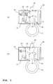
- FIG. 2(a) is a sectional view illustrating the state where the steering lock 20 is locked.
- the locking switch 23 itself serves as a lock pin (manual lock means) 30.
- Handlebars 31 are locked with a distal end of the lock pin 30 engaged with a recess of the handlebars 31, and with a distal end of a slidable slider (retention member) 32 engaged with a projection 36 of the lock pin 30 by an urging force of a spring 34.
- a release control section 15 issues a steering lock release signal, activating the actuator 21 to pivot in the direction of the arrow as shown in FIG. 2(b).
- the actuator 21 is coupled to a link mechanism 33.
- the link mechanism 33 moves along a groove of the slider 32 in the direction opposite to the lock pin 30, bringing the slider 32 out of engagement with the projection of the lock pin 30. This brings the lock pin 30 out of engagement with the recess of the handlebars 31 due to an urging force of a spring 35, thereby automatically releasing the steering lock 20.
- the steering lock 20 is automatically released when the power source 14 of the control unit 10 is turned on. Once the steering lock 20 is automatically released, the steering lock 20 is kept in the state where manual locking is not allowed. When the power source 14 of the control unit 10 is turned off, manual locking is allowed.
- the power source 14 of the control unit 10 of the vehicle is turned on and the steering lock 20 is released. This allows the rider to move the vehicle without starting an engine, facilitating maintenance and other work.
- the steering lock 20 can be manually locked. This can minimize actuating means (actuator) for actuating the steering lock 20 to the size proper to release the steering lock 20.
- the steering lock 20 is kept in the state where manual locking is not allowed. Any accidental operation of the locking switch during riding by the rider, therefore, does not result in locking of the steering lock 20.
- the integral constitution of the manual lock means (lock pin 30) for manually locking the steering lock 20 and the automatic release means (actuator 21) for automatically releasing the steering lock 20 can reduce the size of a release/lock device for the steering lock 20.
- a rider operates the activating switch 16 provided on the vehicle (the step S1) to issue a request signal from the transmitter-receiver 12 provided on the vehicle (the step S2).
- the portable device 11 Upon reception of the request signal, the portable device 11, which the rider carries, sends a code signal back automatically.
- the transmitter-receiver 12 provided on the vehicle receives the code signal (step S3) and identifies the signal with a specific reference code preset by the authentication means 13 (step S4).
- step S5 When the authentication succeeds, meaning the rider is authenticated as the owner of the vehicle, the unlock control section 24 of the control unit 10 issues a release signal (step S5) to automatically release the steering lock 20 (step S6).
- step S5 the unlock control section 24 of the control unit 10 issues a release signal (step S5) to automatically release the steering lock 20 (step S6).
- step S7 the steering lock 20 is kept in the state where manual locking is not allowed (step S8). Manual locking of the steering lock 20 during riding is thereby disabled.
- step S9 When the vehicle comes to a stop after running and the engine is stopped and an off state of the power source of the control unit 10 is determined (step S9), the steering lock 20 is released from the state where manual locking is not allowed during riding. When the rider operates the locking switch 23 (step S10), the steering lock 20 is manually locked.
- FIG. 5 illustrates an example in which the vehicle controller 100 is installed on a two-wheeled motor vehicle 200.
- control unit 10 and the steering lock 20 may be handled as separate configurations, which can improve layout flexibility in the vehicle.
- control unit 10 is located below a seat 50 where extra space is relatively created, while the steering lock 20 is located adjacent to handlebars 31.
- the steering lock 20 is coupled to the control unit 10 via wiring 60, and in response to a release signal from the release control section 15 of the control unit 10, the steering lock 20 is automatically released. Rider's operation of the locking switch 23 disposed adjacent to or integral with the steering lock 20 actuates the manual lock means 22 of the steering lock 20, so that the steering lock 20 is manually locked.
- the activating switch 16 is preferably disposed in the place offering good operability to the rider (e.g. near a speed meter).
- the activating switch 16 is a push switch similar to the locking switch 23 of the steering lock 20
- activation of the authentication system and manual locking of the steering lock 20 are achieved through common operation of "pressing,” providing improved operability.
- the activating switch 16 has the constitution of a two-stage push switch, turning-off operation of the power source of the control unit 10, as well as triggering of authentication can be achieved with the same switch, providing further improved operability.
- the activating switch 16 should be set such that for short pressing (first pressing operation), triggering of authentication is activated and for long pressing (second pressing operation), the power source of the control unit 10 is turned off.
- two-wheeled motor vehicle used herein means a motorcycle, including every motorbike and motor scooter, and, more particularly, is a vehicle which can be turned by tilting the vehicle body.
- a vehicle equipped with two or more front wheels and/or two or more rear wheels, thus having three or four (or more) wheels in total is also included in the "autobicycle.”
- teaching of the present invention may also be applied to other vehicles, as long as a vehicle can take advantage of effects of the invention.
- ATV all terrain vehicles
- the present embodiments can provide a vehicle controller for a straddle-type vehicle, which offers improved maintenance convenience and has an authentication function with excellent operability.
- a vehicle controller for a straddle-type vehicle including: a portable device for transmitting a code signal; and authentication means for receiving and authenticating the code signal, in which if the authentication is determined to be successful, a release signal is issued from a control unit of the vehicle to actuate release means for a steering lock, and in which when power source of the control unit is turned off, lock means for the steering lock is actuated through user's operation of a push-type locking operation element to permit manual locking.
- manual lock means for manually locking the steering lock is formed integrally with automatic release means for automatically releasing the steering lock.
- the manual lock means is kept in the state where manual locking is not allowed until the power source of the control unit is turned off.
- the code signal transmitted from the portable device is transmitted in response to a request signal transmitted in response to user's operation of an activating switch provided in the vehicle, and the activating switch is a push switch.
- the activating switch has the constitution of a two-stage push switch so that the request signal is transmitted from the vehicle in response to user's first pressing operation and the power source of the control unit is turned off in response to user's second pressing operation.
- the description further discloses an embodiment of a straddle-type vehicle incorporating the vehicle controller for a straddle-type vehicle.
- the embodiments provide the vehicle controller for a straddle-type vehicle in which if authentication of a signal transmitted from the portable device is successful, the control unit of the vehicle issues a release signal to release the steering lock. This allows a driver to move the vehicle without starting-up the engine, thereby facilitating maintenance and other work.
- the steering lock can be manually locked. This can minimize actuating means (actuator) for actuating the steering lock to the size proper to release the steering lock.
- the manual lock means for manually locking the steering lock is formed integrally with the automatic release means for automatically releasing the steering lock, thereby reducing the size of a release/unlock device for the steering lock.
- the activating switch operated by the user to control transmission of the request signal for triggering of authentication is a push switch similar to the locking switch operated by the user for manual locking of the steering lock. Different types of operations, therefore, can be achieved through common operation of "pressing,” providing improved operability.
- a vehicle controller for a straddle-type vehicle includes a portable device 11 for transmitting a code signal and authentication means 13 for receiving and authenticating the code signal. If the authentication is determined to be successful, a release signal is issued from a control unit 10 of the vehicle to actuate release means for a steering lock 20 to automatically release the steering lock 20. When a power source 14 of the control unit 10 is turned off, manual locking is allowed. Manual locking of the steering lock 20 is actuated through user's operation of a push-type locking switch 23. Manual lock means 22 for manually locking the steering lock 20 is formed integrally with automatic release means 21 for automatically releasing the steering lock 20.
- a vehicle controller for a straddle type vehicle comprising: a portable device for transmitting a code signal; and authentication means for receiving and authenticating the code signal, wherein if the authentication is determined to be successful, a release signal is issued from a control unit of the vehicle to actuate release means for a steering lock, and wherein when power source of the control unit is turned off, lock means for the steering lock is actuated through user's operation of a push-type locking operation element to permit manual locking.
- manual lock means for manually locking the steering lock may be formed integrally with automatic release means for automatically releasing the steering lock.
- the manual lock means may be kept in the state where manual locking is not allowed until the power source of the control unit is turned off.
- the code signal transmitted from the portable device may be transmitted in response to a request signal transmitted in response to user's operation of an activating switch provided in the vehicle, and wherein the activating switch may be a push switch.
- the description further discloses a fifth aspect, in the vehicle controller for a straddle type vehicle according to a fourth aspect, wherein the activating switch may have the constitution of a two-stage push switch so that the request signal is transmitted from the vehicle in response to user's first pressing operation and the power source of the control unit is turned off in response to user's second pressing operation.
- a straddle type vehicle incorporating the vehicle controller for a straddle type vehicle according to any one of the above first to fifth aspect.
Landscapes
- Engineering & Computer Science (AREA)
- Mechanical Engineering (AREA)
- Lock And Its Accessories (AREA)
- Filtering Of Dispersed Particles In Gases (AREA)
- Steering Devices For Bicycles And Motorcycles (AREA)
Applications Claiming Priority (1)
| Application Number | Priority Date | Filing Date | Title |
|---|---|---|---|
| JP2005148596A JP2006321454A (ja) | 2005-05-20 | 2005-05-20 | 鞍乗型車両の車両制御装置 |
Publications (2)
| Publication Number | Publication Date |
|---|---|
| EP1724165A1 true EP1724165A1 (de) | 2006-11-22 |
| EP1724165B1 EP1724165B1 (de) | 2008-12-24 |
Family
ID=36942294
Family Applications (1)
| Application Number | Title | Priority Date | Filing Date |
|---|---|---|---|
| EP20060010418 Expired - Lifetime EP1724165B1 (de) | 2005-05-20 | 2006-05-19 | Fahrzeugsteuerungsvorrichtung für Spreitzsitz-Fahrzeuge |
Country Status (8)
| Country | Link |
|---|---|
| US (1) | US8130088B2 (de) |
| EP (1) | EP1724165B1 (de) |
| JP (1) | JP2006321454A (de) |
| CN (1) | CN100546851C (de) |
| AT (1) | ATE418480T1 (de) |
| DE (1) | DE602006004391D1 (de) |
| ES (1) | ES2318614T3 (de) |
| TW (1) | TWI302508B (de) |
Cited By (6)
| Publication number | Priority date | Publication date | Assignee | Title |
|---|---|---|---|---|
| EP2065266A1 (de) * | 2007-11-30 | 2009-06-03 | Alpha Corporation | Elektrische Lenkradschlossvorrichtung |
| EP1975049A3 (de) * | 2007-03-27 | 2010-11-10 | Honda Motor Co., Ltd. | Lenkungsmittelsperrvorrichtung |
| JP2011084271A (ja) * | 2009-10-16 | 2011-04-28 | Ldl Technology Sas | ステアリングコラムの自動ロック装置およびその方法 |
| EP3461700A1 (de) * | 2017-09-29 | 2019-04-03 | Honda Motor Co., Ltd. | Sattelfahrzeug |
| EP3566934B1 (de) * | 2018-05-11 | 2022-09-07 | ABUS August Bremicker Söhne KG | Bremsscheibenschloss |
| US12071190B2 (en) | 2018-09-28 | 2024-08-27 | Razor Usa Llc | Scooter steering lock |
Families Citing this family (21)
| Publication number | Priority date | Publication date | Assignee | Title |
|---|---|---|---|---|
| JP2006321452A (ja) * | 2005-05-20 | 2006-11-30 | Yamaha Motor Co Ltd | 鞍乗型車両の車両制御装置 |
| JP2006321453A (ja) * | 2005-05-20 | 2006-11-30 | Yamaha Motor Co Ltd | 鞍乗型車両の車両制御装置 |
| JP5057795B2 (ja) * | 2007-02-13 | 2012-10-24 | ヤマハ発動機株式会社 | スクータ型車両 |
| JP5244379B2 (ja) * | 2007-03-16 | 2013-07-24 | ヤマハ発動機株式会社 | 自動二輪車 |
| DE102007041620A1 (de) * | 2007-09-03 | 2009-03-05 | Huf Hülsbeck & Fürst Gmbh & Co. Kg | Vorrichtung zur Ansteuerung eines Sperrgliedes |
| US7891221B2 (en) * | 2007-10-01 | 2011-02-22 | Alpha Corporation | Electric steering lock device |
| JP5252899B2 (ja) * | 2007-10-01 | 2013-07-31 | 株式会社アルファ | 電動ステアリングロック装置 |
| DE102008032586A1 (de) * | 2008-07-11 | 2010-01-14 | Huf Hülsbeck & Fürst Gmbh & Co. Kg | Verfahren zum Betrieb eines Steuerungssystems eines Motorrads |
| US8353185B2 (en) * | 2009-03-17 | 2013-01-15 | Kabushiki Kaisha Honda Lock | Vehicle handle locking apparatus |
| JP5395493B2 (ja) * | 2009-03-31 | 2014-01-22 | 本田技研工業株式会社 | 車両のハンドルロック装置 |
| US8841881B2 (en) | 2010-06-02 | 2014-09-23 | Bryan Marc Failing | Energy transfer with vehicles |
| TW201341235A (zh) * | 2012-04-06 | 2013-10-16 | New Kailung Gear Co Ltd | 旋轉機構斷電自動鎖定及不正常斷電防鎖裝置 |
| JP6367678B2 (ja) * | 2014-10-09 | 2018-08-01 | 株式会社ユーシン | 電動ステアリングロック装置 |
| JP6746948B2 (ja) * | 2016-02-25 | 2020-08-26 | オムロン株式会社 | ハンドルロックシステム |
| JP6851044B2 (ja) * | 2016-12-22 | 2021-03-31 | 朝日電装株式会社 | エンジン始動装置 |
| EP3339110B1 (de) * | 2016-12-22 | 2020-02-05 | Asahi Denso Co., Ltd. | Motorstartvorrichtung |
| US10449927B2 (en) * | 2017-04-13 | 2019-10-22 | Steering Solutions Ip Holding Corporation | Steering system having anti-theft capabilities |
| WO2019031247A1 (ja) * | 2017-08-07 | 2019-02-14 | 株式会社ホンダロック | 鞍乗型車両用作動許可装置 |
| DE102018111296A1 (de) * | 2018-05-11 | 2019-11-14 | ABUS August Bremicker Söhne KG | Mobiles Schloss |
| CN209642719U (zh) * | 2018-09-06 | 2019-11-15 | Oppo广东移动通信有限公司 | 移动终端 |
| WO2021157025A1 (ja) * | 2020-02-06 | 2021-08-12 | 本田技研工業株式会社 | 鞍乗型車両、通信ユニット、制御方法及び記憶媒体 |
Citations (4)
| Publication number | Priority date | Publication date | Assignee | Title |
|---|---|---|---|---|
| JPH0321575A (ja) | 1989-06-20 | 1991-01-30 | Honda Motor Co Ltd | 車輌盗難防止装置 |
| US5343077A (en) | 1989-06-20 | 1994-08-30 | Honda Giken Kogyo Kk | Electric power supply control device for vehicle |
| JPH06247260A (ja) | 1992-12-28 | 1994-09-06 | Honda Motor Co Ltd | 車両用制御装置 |
| US5965955A (en) * | 1996-10-24 | 1999-10-12 | Yazaki Corporation | Steering locking device |
Family Cites Families (37)
| Publication number | Priority date | Publication date | Assignee | Title |
|---|---|---|---|---|
| JPS6019397B2 (ja) * | 1981-04-30 | 1985-05-16 | 日産自動車株式会社 | 自動車におけるドアの自動施錠装置 |
| JPH07114094B2 (ja) | 1987-07-23 | 1995-12-06 | 株式会社不二工機製作所 | 三動作形圧力スイッチ |
| JPH023592A (ja) | 1987-11-27 | 1990-01-09 | Sanshin Ind Co Ltd | 水上バイク用乗船感知制御装置 |
| DE69029990T2 (de) * | 1989-11-02 | 1997-06-12 | Nissan Motor | Schlüsselloses Schlosssystem für ein Kraftfahrzeug |
| US5319698A (en) | 1992-02-11 | 1994-06-07 | Boat Buddy Sentry, Ltd. | Security system |
| DE4420798C2 (de) | 1994-06-16 | 1996-10-02 | Barbara Catrin Parr | Selbststeueranlage für Wasserfahrzeuge |
| US5854736A (en) | 1994-08-26 | 1998-12-29 | Packard Bell Nec | Peripheral card locking device |
| US5593330A (en) | 1994-12-01 | 1997-01-14 | Yamaha Hatsudoki Kabushiki Kaisha | Lock system for a watercraft |
| US5623245A (en) | 1995-07-31 | 1997-04-22 | Gilmore; Jack R. | Remotely activated vehicle anti-theft and anti-carjacking device |
| US5725228A (en) | 1996-05-28 | 1998-03-10 | Livingston; David T. | Trailerable recreational vehicles and watercraft with rear lights for safe towing on a trailer |
| US6077133A (en) | 1997-07-09 | 2000-06-20 | Sanshin Kogyo Kabushiki Kaisha | Locking device for outboard motor |
| JPH1143093A (ja) | 1997-07-30 | 1999-02-16 | Yamaha Motor Co Ltd | Gps付き小型船舶 |
| DE19908216C2 (de) * | 1999-02-25 | 2001-09-06 | Siemens Ag | Verfahren zum Starten eines Kraftfahrzeugs und Zündstartvorrichtung |
| JP4205261B2 (ja) | 1999-07-14 | 2009-01-07 | ヤマハモーターエレクトロニクス株式会社 | エンジン停止装置 |
| JP2001088789A (ja) | 1999-09-24 | 2001-04-03 | Yamaha Motor Co Ltd | 小型推進艇の盗難防止装置 |
| DE19960958B4 (de) | 1999-12-17 | 2004-10-07 | Robert Bosch Gmbh | Vorrichtung zum Diebstahlschutz |
| JP2001254549A (ja) | 2000-03-10 | 2001-09-21 | Omron Corp | 制御装置 |
| JP2002145182A (ja) | 2000-11-07 | 2002-05-22 | Yamaha Motor Co Ltd | 水上乗物の荷物収納部の蓋構造 |
| JP3851803B2 (ja) | 2001-02-09 | 2006-11-29 | 株式会社東海理化電機製作所 | 電子式車両盗難防止装置 |
| TWI236987B (en) | 2001-02-19 | 2005-08-01 | Honda Motor Co Ltd | Remote lock operation apparatus for light vehicle |
| JP2002256928A (ja) | 2001-02-26 | 2002-09-11 | Yamaha Motor Co Ltd | 水ジェット推進艇のエンジン出力制御装置 |
| DE10125064B4 (de) | 2001-05-23 | 2012-08-30 | Robert Bosch Gmbh | Vorrichtung zur Aktivierung eines Motorrads |
| JP3962236B2 (ja) | 2001-10-25 | 2007-08-22 | ヤマハマリン株式会社 | 船舶制御システム、船舶への制御入力システム、船舶制御装置 |
| DE10203462A1 (de) | 2002-01-28 | 2003-07-31 | Kostal Leopold Gmbh & Co Kg | Elektronische Steuereinrichtung |
| US6809636B2 (en) | 2002-09-16 | 2004-10-26 | Dynamco Pty Ltd | Vehicle immobiliser/alarm |
| JP3844231B2 (ja) | 2002-09-26 | 2006-11-08 | 本田技研工業株式会社 | 自動二輪車の盗難防止装置 |
| TWI232826B (en) | 2002-09-30 | 2005-05-21 | Honda Motor Co Ltd | Electronic key system for vehicle |
| JP4126224B2 (ja) | 2002-12-19 | 2008-07-30 | 株式会社東海理化電機製作所 | エンジン始動制御装置 |
| JP2004276634A (ja) | 2003-03-12 | 2004-10-07 | Kawasaki Heavy Ind Ltd | 小型滑走艇の盗難防止方法及び装置 |
| JP2004346818A (ja) | 2003-05-22 | 2004-12-09 | Yamaha Marine Co Ltd | 小型滑走艇におけるスロットルバルブ制御装置 |
| DE10323402B3 (de) | 2003-05-23 | 2005-01-05 | Siemens Ag | Zugangs- und Benutzungsberechtigungssystem, insbesondere eines Kraftfahrzeuges |
| FR2858592B1 (fr) | 2003-08-06 | 2006-03-17 | Delphi Tech Inc | Systeme pour demarrer un vehicule motorise |
| JP4494736B2 (ja) | 2003-08-08 | 2010-06-30 | 株式会社東海理化電機製作所 | エンジン始動制御装置 |
| JP4289492B2 (ja) | 2004-03-08 | 2009-07-01 | 朝日電装株式会社 | パッシブエントリーシステム |
| JP3872078B2 (ja) | 2004-10-25 | 2007-01-24 | 三菱電機株式会社 | 移動体始動システム |
| JP2006321453A (ja) | 2005-05-20 | 2006-11-30 | Yamaha Motor Co Ltd | 鞍乗型車両の車両制御装置 |
| JP2006321452A (ja) | 2005-05-20 | 2006-11-30 | Yamaha Motor Co Ltd | 鞍乗型車両の車両制御装置 |
-
2005
- 2005-05-20 JP JP2005148596A patent/JP2006321454A/ja not_active Withdrawn
-
2006
- 2006-05-03 TW TW95115740A patent/TWI302508B/zh not_active IP Right Cessation
- 2006-05-19 EP EP20060010418 patent/EP1724165B1/de not_active Expired - Lifetime
- 2006-05-19 DE DE200660004391 patent/DE602006004391D1/de not_active Expired - Lifetime
- 2006-05-19 US US11/419,390 patent/US8130088B2/en not_active Expired - Fee Related
- 2006-05-19 AT AT06010418T patent/ATE418480T1/de not_active IP Right Cessation
- 2006-05-19 ES ES06010418T patent/ES2318614T3/es not_active Expired - Lifetime
- 2006-05-19 CN CNB2006100826360A patent/CN100546851C/zh not_active Expired - Fee Related
Patent Citations (4)
| Publication number | Priority date | Publication date | Assignee | Title |
|---|---|---|---|---|
| JPH0321575A (ja) | 1989-06-20 | 1991-01-30 | Honda Motor Co Ltd | 車輌盗難防止装置 |
| US5343077A (en) | 1989-06-20 | 1994-08-30 | Honda Giken Kogyo Kk | Electric power supply control device for vehicle |
| JPH06247260A (ja) | 1992-12-28 | 1994-09-06 | Honda Motor Co Ltd | 車両用制御装置 |
| US5965955A (en) * | 1996-10-24 | 1999-10-12 | Yazaki Corporation | Steering locking device |
Cited By (9)
| Publication number | Priority date | Publication date | Assignee | Title |
|---|---|---|---|---|
| EP1975049A3 (de) * | 2007-03-27 | 2010-11-10 | Honda Motor Co., Ltd. | Lenkungsmittelsperrvorrichtung |
| US8099986B2 (en) | 2007-03-27 | 2012-01-24 | Honda Motor Co., Ltd. | Steering means locking apparatus |
| EP2065266A1 (de) * | 2007-11-30 | 2009-06-03 | Alpha Corporation | Elektrische Lenkradschlossvorrichtung |
| US7596976B2 (en) | 2007-11-30 | 2009-10-06 | Alpha Corporation | Electric steering lock device |
| CN101445093B (zh) * | 2007-11-30 | 2013-08-28 | 株式会社阿尔发 | 电动转向锁定装置 |
| JP2011084271A (ja) * | 2009-10-16 | 2011-04-28 | Ldl Technology Sas | ステアリングコラムの自動ロック装置およびその方法 |
| EP3461700A1 (de) * | 2017-09-29 | 2019-04-03 | Honda Motor Co., Ltd. | Sattelfahrzeug |
| EP3566934B1 (de) * | 2018-05-11 | 2022-09-07 | ABUS August Bremicker Söhne KG | Bremsscheibenschloss |
| US12071190B2 (en) | 2018-09-28 | 2024-08-27 | Razor Usa Llc | Scooter steering lock |
Also Published As
| Publication number | Publication date |
|---|---|
| ATE418480T1 (de) | 2009-01-15 |
| TWI302508B (en) | 2008-11-01 |
| CN1865069A (zh) | 2006-11-22 |
| DE602006004391D1 (de) | 2009-02-05 |
| EP1724165B1 (de) | 2008-12-24 |
| JP2006321454A (ja) | 2006-11-30 |
| US20060261673A1 (en) | 2006-11-23 |
| CN100546851C (zh) | 2009-10-07 |
| US8130088B2 (en) | 2012-03-06 |
| TW200711920A (en) | 2007-04-01 |
| ES2318614T3 (es) | 2009-05-01 |
Similar Documents
| Publication | Publication Date | Title |
|---|---|---|
| EP1724165B1 (de) | Fahrzeugsteuerungsvorrichtung für Spreitzsitz-Fahrzeuge | |
| EP1975049B1 (de) | Lenkungsmittelsperrvorrichtung | |
| JP4100570B2 (ja) | 車両用ロック装置 | |
| EP1724167B1 (de) | Fahrzeugsteuerungsvorrichtung für ein Spreitzsitz-Fahrzeug | |
| EP1724166B1 (de) | Fahrzeugsteuerungsvorrichtung für Spreitzsitz-Fahrzeug | |
| US20040164850A1 (en) | Motorcycle anti-theft device | |
| JP2004510625A (ja) | モータ駆動車両を始動させるシステム | |
| CN113573973A (zh) | 解锁系统 | |
| JP2006062527A (ja) | 車両の操舵装置 | |
| EP3239026B1 (de) | Fahrzeug | |
| JP4766978B2 (ja) | スマートキーシステムを備えた鞍乗型車両 | |
| JP4274879B2 (ja) | ステアリングロック装置 | |
| JP4733449B2 (ja) | イグニッションスイッチ装置 | |
| JP4305835B2 (ja) | エンジン始動装置 | |
| JP4629498B2 (ja) | ステアリングロック装置 | |
| JP4733455B2 (ja) | ステアリングロック装置 | |
| JP5191415B2 (ja) | イグニッションスイッチ装置 | |
| JP4733450B2 (ja) | イグニッションスイッチ装置 | |
| JP4605776B2 (ja) | ステアリングロック装置 | |
| JP4657837B2 (ja) | イグニッションスイッチ装置 | |
| JP2010125904A (ja) | エンジンの始動制御装置 |
Legal Events
| Date | Code | Title | Description |
|---|---|---|---|
| PUAI | Public reference made under article 153(3) epc to a published international application that has entered the european phase |
Free format text: ORIGINAL CODE: 0009012 |
|
| AK | Designated contracting states |
Kind code of ref document: A1 Designated state(s): AT BE BG CH CY CZ DE DK EE ES FI FR GB GR HU IE IS IT LI LT LU LV MC NL PL PT RO SE SI SK TR |
|
| AX | Request for extension of the european patent |
Extension state: AL BA HR MK YU |
|
| 17P | Request for examination filed |
Effective date: 20061023 |
|
| 17Q | First examination report despatched |
Effective date: 20070112 |
|
| AKX | Designation fees paid |
Designated state(s): AT BE BG CH CY CZ DE DK EE ES FI FR GB GR HU IE IS IT LI LT LU LV MC NL PL PT RO SE SI SK TR |
|
| GRAP | Despatch of communication of intention to grant a patent |
Free format text: ORIGINAL CODE: EPIDOSNIGR1 |
|
| GRAS | Grant fee paid |
Free format text: ORIGINAL CODE: EPIDOSNIGR3 |
|
| GRAA | (expected) grant |
Free format text: ORIGINAL CODE: 0009210 |
|
| AK | Designated contracting states |
Kind code of ref document: B1 Designated state(s): AT BE BG CH CY CZ DE DK EE ES FI FR GB GR HU IE IS IT LI LT LU LV MC NL PL PT RO SE SI SK TR |
|
| REG | Reference to a national code |
Ref country code: GB Ref legal event code: FG4D |
|
| REG | Reference to a national code |
Ref country code: CH Ref legal event code: EP |
|
| REG | Reference to a national code |
Ref country code: IE Ref legal event code: FG4D |
|
| REF | Corresponds to: |
Ref document number: 602006004391 Country of ref document: DE Date of ref document: 20090205 Kind code of ref document: P |
|
| PG25 | Lapsed in a contracting state [announced via postgrant information from national office to epo] |
Ref country code: LT Free format text: LAPSE BECAUSE OF FAILURE TO SUBMIT A TRANSLATION OF THE DESCRIPTION OR TO PAY THE FEE WITHIN THE PRESCRIBED TIME-LIMIT Effective date: 20081224 |
|
| REG | Reference to a national code |
Ref country code: ES Ref legal event code: FG2A Ref document number: 2318614 Country of ref document: ES Kind code of ref document: T3 |
|
| PG25 | Lapsed in a contracting state [announced via postgrant information from national office to epo] |
Ref country code: NL Free format text: LAPSE BECAUSE OF FAILURE TO SUBMIT A TRANSLATION OF THE DESCRIPTION OR TO PAY THE FEE WITHIN THE PRESCRIBED TIME-LIMIT Effective date: 20081224 Ref country code: LV Free format text: LAPSE BECAUSE OF FAILURE TO SUBMIT A TRANSLATION OF THE DESCRIPTION OR TO PAY THE FEE WITHIN THE PRESCRIBED TIME-LIMIT Effective date: 20081224 Ref country code: FI Free format text: LAPSE BECAUSE OF FAILURE TO SUBMIT A TRANSLATION OF THE DESCRIPTION OR TO PAY THE FEE WITHIN THE PRESCRIBED TIME-LIMIT Effective date: 20081224 Ref country code: SI Free format text: LAPSE BECAUSE OF FAILURE TO SUBMIT A TRANSLATION OF THE DESCRIPTION OR TO PAY THE FEE WITHIN THE PRESCRIBED TIME-LIMIT Effective date: 20081224 Ref country code: PL Free format text: LAPSE BECAUSE OF FAILURE TO SUBMIT A TRANSLATION OF THE DESCRIPTION OR TO PAY THE FEE WITHIN THE PRESCRIBED TIME-LIMIT Effective date: 20081224 |
|
| NLV1 | Nl: lapsed or annulled due to failure to fulfill the requirements of art. 29p and 29m of the patents act | ||
| PG25 | Lapsed in a contracting state [announced via postgrant information from national office to epo] |
Ref country code: RO Free format text: LAPSE BECAUSE OF FAILURE TO SUBMIT A TRANSLATION OF THE DESCRIPTION OR TO PAY THE FEE WITHIN THE PRESCRIBED TIME-LIMIT Effective date: 20081224 Ref country code: BG Free format text: LAPSE BECAUSE OF FAILURE TO SUBMIT A TRANSLATION OF THE DESCRIPTION OR TO PAY THE FEE WITHIN THE PRESCRIBED TIME-LIMIT Effective date: 20090324 Ref country code: EE Free format text: LAPSE BECAUSE OF FAILURE TO SUBMIT A TRANSLATION OF THE DESCRIPTION OR TO PAY THE FEE WITHIN THE PRESCRIBED TIME-LIMIT Effective date: 20081224 Ref country code: BE Free format text: LAPSE BECAUSE OF FAILURE TO SUBMIT A TRANSLATION OF THE DESCRIPTION OR TO PAY THE FEE WITHIN THE PRESCRIBED TIME-LIMIT Effective date: 20081224 |
|
| PG25 | Lapsed in a contracting state [announced via postgrant information from national office to epo] |
Ref country code: CZ Free format text: LAPSE BECAUSE OF FAILURE TO SUBMIT A TRANSLATION OF THE DESCRIPTION OR TO PAY THE FEE WITHIN THE PRESCRIBED TIME-LIMIT Effective date: 20081224 Ref country code: SE Free format text: LAPSE BECAUSE OF FAILURE TO SUBMIT A TRANSLATION OF THE DESCRIPTION OR TO PAY THE FEE WITHIN THE PRESCRIBED TIME-LIMIT Effective date: 20090324 Ref country code: PT Free format text: LAPSE BECAUSE OF FAILURE TO SUBMIT A TRANSLATION OF THE DESCRIPTION OR TO PAY THE FEE WITHIN THE PRESCRIBED TIME-LIMIT Effective date: 20090525 Ref country code: IS Free format text: LAPSE BECAUSE OF FAILURE TO SUBMIT A TRANSLATION OF THE DESCRIPTION OR TO PAY THE FEE WITHIN THE PRESCRIBED TIME-LIMIT Effective date: 20090424 Ref country code: AT Free format text: LAPSE BECAUSE OF FAILURE TO SUBMIT A TRANSLATION OF THE DESCRIPTION OR TO PAY THE FEE WITHIN THE PRESCRIBED TIME-LIMIT Effective date: 20081224 |
|
| PG25 | Lapsed in a contracting state [announced via postgrant information from national office to epo] |
Ref country code: SK Free format text: LAPSE BECAUSE OF FAILURE TO SUBMIT A TRANSLATION OF THE DESCRIPTION OR TO PAY THE FEE WITHIN THE PRESCRIBED TIME-LIMIT Effective date: 20081224 |
|
| PG25 | Lapsed in a contracting state [announced via postgrant information from national office to epo] |
Ref country code: DK Free format text: LAPSE BECAUSE OF FAILURE TO SUBMIT A TRANSLATION OF THE DESCRIPTION OR TO PAY THE FEE WITHIN THE PRESCRIBED TIME-LIMIT Effective date: 20081224 |
|
| PLBE | No opposition filed within time limit |
Free format text: ORIGINAL CODE: 0009261 |
|
| STAA | Information on the status of an ep patent application or granted ep patent |
Free format text: STATUS: NO OPPOSITION FILED WITHIN TIME LIMIT |
|
| 26N | No opposition filed |
Effective date: 20090925 |
|
| PG25 | Lapsed in a contracting state [announced via postgrant information from national office to epo] |
Ref country code: MC Free format text: LAPSE BECAUSE OF NON-PAYMENT OF DUE FEES Effective date: 20090531 |
|
| PG25 | Lapsed in a contracting state [announced via postgrant information from national office to epo] |
Ref country code: IE Free format text: LAPSE BECAUSE OF NON-PAYMENT OF DUE FEES Effective date: 20090519 |
|
| PG25 | Lapsed in a contracting state [announced via postgrant information from national office to epo] |
Ref country code: GR Free format text: LAPSE BECAUSE OF FAILURE TO SUBMIT A TRANSLATION OF THE DESCRIPTION OR TO PAY THE FEE WITHIN THE PRESCRIBED TIME-LIMIT Effective date: 20090325 |
|
| REG | Reference to a national code |
Ref country code: CH Ref legal event code: PL |
|
| PG25 | Lapsed in a contracting state [announced via postgrant information from national office to epo] |
Ref country code: LI Free format text: LAPSE BECAUSE OF NON-PAYMENT OF DUE FEES Effective date: 20100531 Ref country code: CH Free format text: LAPSE BECAUSE OF NON-PAYMENT OF DUE FEES Effective date: 20100531 |
|
| PG25 | Lapsed in a contracting state [announced via postgrant information from national office to epo] |
Ref country code: LU Free format text: LAPSE BECAUSE OF NON-PAYMENT OF DUE FEES Effective date: 20090519 |
|
| PG25 | Lapsed in a contracting state [announced via postgrant information from national office to epo] |
Ref country code: HU Free format text: LAPSE BECAUSE OF FAILURE TO SUBMIT A TRANSLATION OF THE DESCRIPTION OR TO PAY THE FEE WITHIN THE PRESCRIBED TIME-LIMIT Effective date: 20090625 |
|
| PG25 | Lapsed in a contracting state [announced via postgrant information from national office to epo] |
Ref country code: TR Free format text: LAPSE BECAUSE OF FAILURE TO SUBMIT A TRANSLATION OF THE DESCRIPTION OR TO PAY THE FEE WITHIN THE PRESCRIBED TIME-LIMIT Effective date: 20081224 |
|
| PG25 | Lapsed in a contracting state [announced via postgrant information from national office to epo] |
Ref country code: CY Free format text: LAPSE BECAUSE OF FAILURE TO SUBMIT A TRANSLATION OF THE DESCRIPTION OR TO PAY THE FEE WITHIN THE PRESCRIBED TIME-LIMIT Effective date: 20081224 |
|
| REG | Reference to a national code |
Ref country code: FR Ref legal event code: PLFP Year of fee payment: 11 |
|
| PGFP | Annual fee paid to national office [announced via postgrant information from national office to epo] |
Ref country code: ES Payment date: 20160512 Year of fee payment: 11 Ref country code: DE Payment date: 20160520 Year of fee payment: 11 Ref country code: GB Payment date: 20160520 Year of fee payment: 11 |
|
| PGFP | Annual fee paid to national office [announced via postgrant information from national office to epo] |
Ref country code: FR Payment date: 20160520 Year of fee payment: 11 Ref country code: IT Payment date: 20160524 Year of fee payment: 11 |
|
| REG | Reference to a national code |
Ref country code: DE Ref legal event code: R119 Ref document number: 602006004391 Country of ref document: DE |
|
| GBPC | Gb: european patent ceased through non-payment of renewal fee |
Effective date: 20170519 |
|
| REG | Reference to a national code |
Ref country code: FR Ref legal event code: ST Effective date: 20180131 |
|
| PG25 | Lapsed in a contracting state [announced via postgrant information from national office to epo] |
Ref country code: DE Free format text: LAPSE BECAUSE OF NON-PAYMENT OF DUE FEES Effective date: 20171201 Ref country code: GB Free format text: LAPSE BECAUSE OF NON-PAYMENT OF DUE FEES Effective date: 20170519 |
|
| PG25 | Lapsed in a contracting state [announced via postgrant information from national office to epo] |
Ref country code: IT Free format text: LAPSE BECAUSE OF NON-PAYMENT OF DUE FEES Effective date: 20170519 Ref country code: FR Free format text: LAPSE BECAUSE OF NON-PAYMENT OF DUE FEES Effective date: 20170531 |
|
| REG | Reference to a national code |
Ref country code: ES Ref legal event code: FD2A Effective date: 20180705 |
|
| PG25 | Lapsed in a contracting state [announced via postgrant information from national office to epo] |
Ref country code: ES Free format text: LAPSE BECAUSE OF NON-PAYMENT OF DUE FEES Effective date: 20170520 |