EP1724401A2 - Elektrisch gesteuerte Mischbatterie - Google Patents
Elektrisch gesteuerte Mischbatterie Download PDFInfo
- Publication number
- EP1724401A2 EP1724401A2 EP06425303A EP06425303A EP1724401A2 EP 1724401 A2 EP1724401 A2 EP 1724401A2 EP 06425303 A EP06425303 A EP 06425303A EP 06425303 A EP06425303 A EP 06425303A EP 1724401 A2 EP1724401 A2 EP 1724401A2
- Authority
- EP
- European Patent Office
- Prior art keywords
- water
- flow rate
- regulating
- mixing
- potentiometer
- Prior art date
- Legal status (The legal status is an assumption and is not a legal conclusion. Google has not performed a legal analysis and makes no representation as to the accuracy of the status listed.)
- Withdrawn
Links
- XLYOFNOQVPJJNP-UHFFFAOYSA-N water Substances O XLYOFNOQVPJJNP-UHFFFAOYSA-N 0.000 claims abstract description 136
- 230000001105 regulatory effect Effects 0.000 claims abstract description 74
- 238000003780 insertion Methods 0.000 claims abstract description 3
- 230000037431 insertion Effects 0.000 claims abstract description 3
- 230000001755 vocal effect Effects 0.000 claims abstract description 3
- 230000008859 change Effects 0.000 claims description 2
- 238000012545 processing Methods 0.000 claims description 2
- 238000000034 method Methods 0.000 abstract description 2
- 230000008569 process Effects 0.000 abstract description 2
- 238000009434 installation Methods 0.000 description 7
- 239000000463 material Substances 0.000 description 3
- 230000006870 function Effects 0.000 description 2
- 238000012423 maintenance Methods 0.000 description 2
- 230000000295 complement effect Effects 0.000 description 1
- 229920002457 flexible plastic Polymers 0.000 description 1
- 230000004048 modification Effects 0.000 description 1
- 238000012986 modification Methods 0.000 description 1
- 229920003023 plastic Polymers 0.000 description 1
- 230000008439 repair process Effects 0.000 description 1
- 239000000523 sample Substances 0.000 description 1
- 230000035807 sensation Effects 0.000 description 1
- 238000011144 upstream manufacturing Methods 0.000 description 1
Images



Classifications
-
- E—FIXED CONSTRUCTIONS
- E03—WATER SUPPLY; SEWERAGE
- E03C—DOMESTIC PLUMBING INSTALLATIONS FOR FRESH WATER OR WASTE WATER; SINKS
- E03C1/00—Domestic plumbing installations for fresh water or waste water; Sinks
- E03C1/02—Plumbing installations for fresh water
- E03C1/05—Arrangements of devices on wash-basins, baths, sinks, or the like for remote control of taps
- E03C1/055—Electrical control devices, e.g. with push buttons, control panels or the like
Definitions
- the present invention concerns devices for mixing water and regulating the flow rate and in particular it concerns a new system for mixing water and regulating the flow rate comprising solenoid valves and an electric control and supply unit, in particular for hydraulic systems for sanitary water.
- Hydraulic systems for the supply of sanitary water are known, which are commonly installed in civil, commercial, industrial buildings, that is, wherever there are civil and industrial users to which water must be provided.
- Hydraulic systems for sanitary water are known and widespread, which comprise two distinct piping lines, one for cold water and the other for hot water, that convey water to every single sanitary fixture, that is, basin, shower, etc., and wherein water is mixed and the flow rate of the supplied water is regulated at the level of the mixer tap.
- Taps for sanitary fixtures like basins, showers, etc which comprise a tap or mixer, and one or more knobs or levers for regulating the water flow rate.
- Said knobs or levers have the function to open or close to a varying degree the hydraulic valves, or gate valves, positioned inside the pipes leading to the sanitary fixture.
- the taps equipped with regulating knobs usually comprise one or two knobs for opening and closing the hydraulic valve of the hot or cold water pipe.
- the user, opening or closing one or both of said knobs is able to regulate the temperature and the flow rate of the water that flows out of the mixer tap.
- valve units which are used for taps with regulating knobs.
- valve units are devices having a substantially cylindrical shape, with a main body threaded in at least two parts, in such a way as to be able to be connected and fixed both to said regulating knobs and to the body of the tap itself.
- Said valve units comprise a further threaded element that, when screwed or unscrewed due to the rotation of the main component of the valve unit, is lifted or lowered, thus functioning as a gate for the pipe that supplies water to the tap.
- the rotation of said regulating knobs causes the corresponding water supply pipe to open or close, thus regulating the water flow rate.
- the taps equipped with lever have the same operating principle, but are used differently.
- Said taps comprise a lever that, if rotated on the horizontal plane, that is, to the right or to the left, adjusts the water temperature, that is, the ratio between the flow rates of the hot and cold water pipes, while if rotated on the vertical plane, that is, lifted or lowered, adjusts the flow rate of the water to be supplied.
- Said cartridges are devices comprising a substantially cylindrical external body, whose bottom is provided with two or more holes, and wherein inside said cylindrical body there are suitable moving elements, usually flat and circular in shape.
- the known cartridges are inserted in the tap and are equipped, on the top, with a small lever connected to the regulating lever of said tap.
- the small lever of the cartridge is moved to an inclined position, thus opening or closing the hole through which the water to be dispensed can reach the tap and flow out.
- the greater or smaller opening of said hole determines the flow rate of the dispensed water.
- Hydraulic systems with two distinct water pipes present several drawbacks, first of all the high labour cost for installation and maintenance.
- Single-pipe hydraulic systems for sanitary water are also known, that is, systems comprising a single pipe that supplies the already mixed water to the corresponding sanitary fixture.
- water is mixed before being conveyed into the supply pipe, and mixing takes place in a manifold-mixer, where the two hot and cold water pipes arrive and from which a single supply pipe branches off for each sanitary fixture.
- the water properly mixed in such a way as to obtain the desired temperature and flow rate, reaches the sanitary fixture through said single supply pipe, made of a flexible plastic material.
- Said mixed water supply pipe is housed in sheaths, channels, hoses or the like, so that in case of replacement it can be simply withdrawn from its seat, with no need for any wall demolition work.
- Hot and cold water are thus mixed before being conveyed into the supply pipe, and mixing takes place in said manifold-mixer, usually in proximity to the boiler.
- Said manifold-mixer comprises, for this purpose, at least one three-way solenoid valve, connected to the hot and cold water pipes and to the water supply pipe.
- Each supply pipe thus brings water to the corresponding sanitary fixture, the mixing ratio and the flow rate of the water to be dispensed having already been regulated by said solenoid valve, one solenoid valve being provided for each water supply pipe.
- the mixing ratio is regulated by the user through a regulating knob that, via electric wires connected to the solenoid valve or to the corresponding control circuit, controls the operation of the manifold-mixer.
- the known manifolds-mixers of the hydraulic systems for sanitary water with one single pipe are thus reached by the two hot and cold water pipes, and said pipes have as many branches as the number of solenoid valves.
- the known devices for mixing water and regulating the flow rate are not sufficiently compact and are also difficult to install; when one of said solenoid valves must be replaced, the operation is excessively complex and requires even a temporary interruption of the supply of water of the whole system.
- a new system for mixing water and regulating the flow rate has been designed and implemented, equipped with solenoid valves and an electric control unit, particularly for single-pipe hydraulic systems, with one or more taps with electronic valve unit and/or one or more mixer taps with electronic cartridge.
- the main aim of the present invention is to carry out the mixing of hot and cold water before the water is conveyed into the supply pipe, so that when the water to be dispensed reaches the sanitary fixture it has already been mixed, according to the temperature and flow rate desired by the user.
- Another aim of the present invention is to allow the flow rate of the water reaching the sanitary fixture to be regulated according to the user's needs.
- Another aim of the present invention is to carry out a system that is compact and easy to install.
- a further aim of the present invention is to facilitate maintenance and replacement of the solenoid valves.
- Another aim of the present invention is to make it unnecessary to replace the common taps with regulating knobs or the common mixer taps with regulating levers.
- a further aim of the present invention is to make it possible to transform any traditional pre-existing tap or mixer tap with manually-operated regulating knobs/levers into a tap or mixer tap with electronically operated knobs/levers, keeping its appearance and functionality unchanged.
- a further aim of the present invention is to allow the installation of knobs and/or levers and/or button panels for regulating the flow rate and the temperature of the water to be dispensed even not in proximity to the taps.
- the invention is constituted - as to its main components - by an electric control and supply unit, a manifold-mixer comprising at least one solenoid valve connected to at least one potentiometer, one or more water supply pipes, one or more taps and/or mixer taps and one or more knobs and/or levers and/or button panels and/or displays and/or other devices for regulating the flow rate and mixing the water that is being delivered.
- a manifold-mixer comprising at least one solenoid valve connected to at least one potentiometer, one or more water supply pipes, one or more taps and/or mixer taps and one or more knobs and/or levers and/or button panels and/or displays and/or other devices for regulating the flow rate and mixing the water that is being delivered.
- Said manifold-mixer is preferably installed upstream of the sanitary water supply pipe, typically in proximity to the boiler.
- the manifold-mixer comprises one or more solenoid valves, each one of which is connected to the two hot and cold water pipes and to one supply pipe.
- Said supply pipe is a flexible pipe made of plastic material resistant to thermal and mechanic stress due to the passage of the water conveyed to the different sanitary fixtures.
- Each solenoid valve is provided with two through holes in which the hot and cold water pipes are inserted and connected, both pipes being provided with suitable holes and pipe fittings for allowing water to be fed into the supply pipe.
- Said solenoid valve comprises two motors for hydraulic valves that control the opening and closing of said holes and is electrically connected, through two or more electric wires, to an adjusting device like a potentiometer that in turn is directly or indirectly connected to one or more regulating knobs and/or levers and/or button panels and/or to said electric control and supply unit.
- the new system for mixing water and regulating the flow rate comprises at least one solenoid valve for each supply pipe, that is, one solenoid valve for each sanitary fixture, each valve being controlled by a potentiometer connected for example to one or more regulating knobs or levers for each sanitary fixture.
- Each solenoid valve also comprises an electric control and supply unit that provides for decoding and processing the data coming from said potentiometer and for feeding the solenoid valve that regulates the mixing ratio and the flow rate of the water to be conveyed to the sanitary fixture.
- each potentiometer determines the data corresponding to the flow rate of hot water and cold water and sends them to said electronic control and supply unit, which operates the corresponding solenoid valve, that is, the motors of the hydraulic valves, so that hot and cold water can be properly mixed according to the user's requirements.
- the new system for regulating and mixing the water being delivered comprises one or more taps with regulating knobs and/or one or more taps with regulating lever.
- each one of said taps with knobs comprises at least one valve unit for each regulating knob, wherein each one of said valve units is constituted - as to its main components - by a main body for connection and attachment to the fixed support of the regulating knob, a rotary spindle connected to said regulating knob and a potentiometer electrically connected, through said electric wires, to the corresponding solenoid valve of said manifold-mixer.
- the rotation of the regulating knob causes the rotation of the rotary spindle of the valve unit and therefore regulates the voltage transmitted by the potentiometer, through the electric wires, to the solenoid valve of the manifold-mixer or to said control and supply unit.
- the user has the impression of turning a normal tap, while he/she is actually operating a potentiometer inserted in the valve unit, which transmits a signal to the corresponding solenoid valve that in turn causes the opening or closing of the hot or cold water pipes, thus mixing the water to be supplied and regulating its flow rate, according to the rotation of said knob, that is, according to the user's needs.
- the new system comprises one or more taps with regulating lever and electronic cartridge.
- Said electronic cartridge comprises an external, substantially cylindrical body that is identical to that of standard cartridges and therefore is suited to be inserted in the mixer taps with regulating lever of the known type, wherein said cartridge is equipped with a small lever positioned vertically on the top of said cylindrical body and connected to the regulating lever, with a substantially cylindrical rotary element positioned horizontally in the cylindrical body and with two potentiometers.
- the first potentiometer controls the mixing of hot and cold water, that is, regulates the relevant flow rates and therefore the temperature of the water being dispensed, and is electrically connected to said rotary element on the horizontal plane, while the second potentiometer, which is responsible for regulating the flow rate, is electrically connected to said small lever rotating on the vertical plane and both said potentiometers are also connected, through said electric wires, to the corresponding solenoid valve of said manifold-mixer.
- the rotation to the right or to the left of the adjusting lever of the tap determines the rotation of said rotary element around its vertical axis on the horizontal plane, thus causing the rotation of the moving cursor of the mixing potentiometer connected to it.
- the electric signal is transmitted, through two or more electric wires, to the corresponding solenoid valve of said manifold-mixer, where the mixing of cold and hot water is regulated, and/or to said electric control and supply unit.
- the electric signal is sent, through two or more electric wires, to said electric control and supply unit and/or to the solenoid valve of said manifold-mixer, where the position of said solenoid valve determines the flow rate of the water to be dispensed.
- valve unit with potentiometer and/or of said cartridge with potentiometers makes it possible to obtain regulating devices that are absolutely similar to the known ones, that is, taps with adjusting knobs or lever.
- the potentiometers that control the solenoid valves can be regulated with common knobs or joysticks and contained in a simple case that can be integral with the sanitary fixture or positioned on a wall, not necessarily in proximity to the sanitary fixture itself.
- the invention may also comprise one or more sensors (flood, temperature, pressure sensors, etc) that improve the operation and use of the hydraulic system for sanitary water.
- said electric control and supply unit may cause the interruption of the supply of water in case of uncontrolled water outflows.
- the installation of a temperature sensor connected to an adjusting device allows the user to read and consequently set the temperature of the water to be dispensed through the tap of the sanitary fixture before its use.
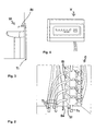
- the manifold-mixer (C) comprises a solenoid valve (Ei) for each sanitary fixture (Ui) to be fed, and each solenoid valve (Ei) is provided with two through holes (Fc) and (Ff), for the insertion of the hot water pipe (Tc) and of the cold water pipe (Tf), respectively.
- Said solenoid valves (Ei), being provided with said through holes (F1) and (F2), may all be connected to the same two hot water (Tc) and cold water (Tf) pipes, and can be positioned side by side or overlapped, as shown in Figure 2.
- the solenoid valve (Ei) is provided with a further hole (F3) for inserting the supply pipe (Ti) that conveys water from said solenoid valve (Ei) to the sanitary fixture (Ui).
- Each solenoid valve (Ei) also comprises two motors (M1) and (M2) that control the hydraulic valves (W1) and (W2) responsible for regulating the flow rates of the hot and cold water coming from the pipes (Tc) and (Tf).
- Each solenoid valve (Ei) of the manifold-mixer (C) is connected to an adjusting device, for example one or more potentiometers (P)/(Pm, Pp), through two or more electric wires.
- potentiometers (P)/(Pm, Pp) are controlled and regulated by means of one or more adjusting knobs (N)/lever (L) of the tap (Ri) of each sanitary fixture (Ui) to which water must be delivered or through the electric control and supply unit (Zi).
- the electric control and supply unit (Zi) has the function to receive, decode and process the data sent by said adjusting knobs (N)/lever (L) of the taps (Ri) and by any sensors used, such as a flood sensor (Sa), a temperature sensor, or any other sensor.
- sensors used such as a flood sensor (Sa), a temperature sensor, or any other sensor.
- the invention may also comprise a display (Y), connected to said temperature sensor, that indicates, in addition to the value of the flow rate, also the value of the temperature of the water present in the supply pipe (Ti) and ready to be dispensed.
- Y a display
- the user can read the temperature and the flow rate of the water that is going to be dispensed and if necessary decide whether to use the button panel and/or the adjusting knobs (N)/lever (L) in order to modify the mixing ratio and the flow rate of the water before use.
- This configuration is particularly useful for showers or other sanitary fixtures, in fact the user comes in contact with the water only when the desired temperature has been reached, which allows unpleasant sensations of excessive cold or hot to be avoided.
- the position of the solenoid valve (Ei) is set according to the position of the knob (N)/lever (L) of the tap (Ri), thus regulating the operation of the motors (M1) and (M2) and, consequently, the mixing ratio, temperature and flow rate of the water conveyed to the sanitary fixtures (Ui) through the supply pipe (Ti).
- Each one of said taps (Ri) is connected to the corresponding supply pipe (Ti), wherein said supply pipe (Ti) is in turn connected to said manifold-mixer (C) where the position of the solenoid valve (Ei) determines the mixing ratio and the flow rate of the dispensed water.
- said solenoid valve (Ei) is connected, through two or more of said electric wires (1) and (2), to the valve unit (V), which in turn is connected to and screwed into said adjusting knob (N), of known type.
- the main body (V1) of said valve unit (V) is threaded, so that it can be fastened to the fixed support (N1) of the adjusting knob (N), and comprises a spindle (V2) whose rotation is caused by the rotation of the adjusting knob (N).
- Said valve unit (V) comprises a bottom chamber (R) that houses a potentiometer (P).
- the rotation of the potentiometer control is in turn caused by the rotation of the adjusting knob (N), transmitted by the spindle (V2) of the valve unit (V).
- the rotation of said adjusting knob (N) thus causes the rotation of said spindle (V2) that, through the potentiometer (P) and the electric wires (1) and (2), controls the position of the solenoid valve (Ei) that regulates the mixing ratio and the flow rate of the water to be dispensed.
- one or more of the taps (Ri) may be of the type with adjusting lever (L).
- Each one of said taps (Ri) is connected to the corresponding supply pipe (Ti), wherein said supply pipe (Ti) is in turn connected to said manifold-mixer (C) where the position of the solenoid valve (Ei) determines the mixing ratio and the flow rate of the dispensed water.
- Said solenoid valve (Ei) is connected, through two or more electric wires, to the cartridge (D), which in turn is inserted and fixed into the tap (Ri) and connected to the adjusting lever (L).
- the cylindrical body (D1) of said cartridge (D) contains a disc (D2) on which the mixing potentiometer (Pm) is housed.
- the mixing potentiometer (Pm) is connected to a rotary element (D3), substantially cylindrical in shape, which is also housed on said disc (D2).
- Said rotary element (D3) comprises teeth (D3') that mesh with the teeth of the moving cursor (Pm') of the mixing potentiometer (Pm), so that the rotation of the small lever (D4) on the horizontal plane causes the rotation of said rotary element (D3) hinged to it on the horizontal plane.
- the rotation of the rotary element (D3) in turn shifts said movig cursor of the mixing potentiometer (Pm) that sends the relevant electric signal to the solenoid valve (Ei).
- the cartridge (D) also comprises a small lever (D4), inserted in the cylindrical body (D1) and connected to said adjusting lever (L).
- Said small lever (D4) is in turn connected also to the flow rate potentiometer (Pp), so that shifting said small lever (D4) means moving the cursor of said flow rate potentiometer (Pp), which will send the relevant electric signal to the corresponding solenoid valve (Ei).
- said small lever (D4) comprises, in its lower part, teeth (D4') that mesh with the teeth of the moving cursor (Pp') of the flow rate potentiometer (Pp), in such a way that the rotation of said small lever (D4) on the vertical plane shifts said moving cursor (Pp') of the flow rate potentiometer (Pp).
- the user to regulate the mixing ratio of the dispensed water, must use the adjusting lever (L), rotating it sideways, while to regulate the flow rate the user must lift or lower said adjusting lever (L).
- the user uses the tap with adjusting lever (L) as if it were a common tap with hydraulic cartridge.
- a presence detector can also be included, which regulates the water flow rate by adopting preset values.
- a vocal control device can also be employed to regulate the total flow rate and the mixing ratio of the flow being dispensed.
Landscapes
- Health & Medical Sciences (AREA)
- Life Sciences & Earth Sciences (AREA)
- Engineering & Computer Science (AREA)
- Hydrology & Water Resources (AREA)
- Public Health (AREA)
- Water Supply & Treatment (AREA)
- Multiple-Way Valves (AREA)
- Domestic Plumbing Installations (AREA)
Applications Claiming Priority (3)
| Application Number | Priority Date | Filing Date | Title |
|---|---|---|---|
| ITPD20050131 ITPD20050131A1 (it) | 2005-05-06 | 2005-05-06 | Sistema di miscelazione e regolazione della portata d'acqua con elettrovalvole e unita' di controllo ed alimentazione per impianti idraulici sanitari monotubo |
| ITPD20050129 ITPD20050129A1 (it) | 2005-05-06 | 2005-05-06 | Cartucci dotata di dispositivi eletrici elettronici per dispositivi di regolazione della miscelazione e della portata d'acqua erogata in sistemi idraulici sanitari |
| ITPD20050130 ITPD20050130A1 (it) | 2005-05-06 | 2005-05-06 | Vitone dotato di dispositivi elettrici elettronici per regolare la temperatura e la portata d'acqua erogata in sistemi idraulici sanitari |
Publications (2)
| Publication Number | Publication Date |
|---|---|
| EP1724401A2 true EP1724401A2 (de) | 2006-11-22 |
| EP1724401A3 EP1724401A3 (de) | 2007-08-29 |
Family
ID=36691700
Family Applications (1)
| Application Number | Title | Priority Date | Filing Date |
|---|---|---|---|
| EP06425303A Withdrawn EP1724401A3 (de) | 2005-05-06 | 2006-05-03 | Elektrisch gesteuerte Mischbatterie |
Country Status (1)
| Country | Link |
|---|---|
| EP (1) | EP1724401A3 (de) |
Cited By (3)
| Publication number | Priority date | Publication date | Assignee | Title |
|---|---|---|---|---|
| WO2009019731A3 (en) * | 2007-08-03 | 2009-03-26 | Paolo Andreotti | Electronic device for mixing water and regulating the flow rate |
| ITMI20081992A1 (it) * | 2008-11-11 | 2010-05-12 | Fima Carlo Frattini S P A | Rubinetto elettronico |
| WO2015134491A1 (en) * | 2014-03-03 | 2015-09-11 | Singley Brent Richard | Flood prevention device |
Family Cites Families (3)
| Publication number | Priority date | Publication date | Assignee | Title |
|---|---|---|---|---|
| DE3211188C2 (de) * | 1982-03-26 | 1984-01-12 | Danfoss A/S, 6430 Nordborg | Steuereinrichtung für ein Proportionalventil |
| NO155261C (no) * | 1984-02-22 | 1987-03-04 | Lyng Ind As | Sanitaersystem for levering av varmt og kaldt vann. |
| FI891208A7 (fi) * | 1989-03-14 | 1990-09-15 | Oras Oy | Elektriskt styrd blandningskran. |
-
2006
- 2006-05-03 EP EP06425303A patent/EP1724401A3/de not_active Withdrawn
Cited By (6)
| Publication number | Priority date | Publication date | Assignee | Title |
|---|---|---|---|---|
| WO2009019731A3 (en) * | 2007-08-03 | 2009-03-26 | Paolo Andreotti | Electronic device for mixing water and regulating the flow rate |
| ITMI20081992A1 (it) * | 2008-11-11 | 2010-05-12 | Fima Carlo Frattini S P A | Rubinetto elettronico |
| CN101737531A (zh) * | 2008-11-11 | 2010-06-16 | 飞马卡罗弗拉蒂尼股份公司 | 电子龙头 |
| EP2184413A3 (de) * | 2008-11-11 | 2013-01-09 | Fima Carlo Frattini S.P.A. | Elektronischer Wasserhahn |
| WO2015134491A1 (en) * | 2014-03-03 | 2015-09-11 | Singley Brent Richard | Flood prevention device |
| US10316457B2 (en) | 2014-03-03 | 2019-06-11 | Brent Richard SINGLEY | Flood prevention device |
Also Published As
| Publication number | Publication date |
|---|---|
| EP1724401A3 (de) | 2007-08-29 |
Similar Documents
| Publication | Publication Date | Title |
|---|---|---|
| WO2009019731A2 (en) | Electronic device for mixing water and regulating the flow rate | |
| US6446875B1 (en) | Water temperature and pressure control system | |
| US5170361A (en) | Fluid temperature, flow rate, and volume control system | |
| US8516628B2 (en) | Flow control apparatus and method | |
| US8606413B2 (en) | Water management system | |
| US4870986A (en) | Dispensing system | |
| EP0195271A2 (de) | Wasserversorgungsinstallation für Waschzwecke | |
| CN102282519B (zh) | 用于自来水的电子可调节混合装置 | |
| EP3321428A1 (de) | Sanitärarmatur mit bypass-ventil | |
| US20100287695A1 (en) | Valve apparatus and system | |
| EP2995728B1 (de) | Berührungsfreie automatische wasserversorgungsvorrichtung und verfahren | |
| EP1724401A2 (de) | Elektrisch gesteuerte Mischbatterie | |
| US20140182691A1 (en) | Hot and cold water mixer | |
| US20050251906A1 (en) | Automatic bathtub filing control system | |
| US4908886A (en) | Dispensing system | |
| US8739827B2 (en) | Single-lever mixing gear for a plumbing fixture | |
| DE102008053879B4 (de) | Elektrische Sanitärarmatur | |
| EP0299696A2 (de) | Temperatur-, Durchfluss- und Volumensteuerungssystem für Flüssigkeit | |
| DE102012100097B4 (de) | Elektronische Sanitärarmatur, insbesondere für Waschtische | |
| EP1710480A2 (de) | Mischbatterie | |
| US9926688B2 (en) | Connecting unit for a kitchen mixer tap and method for placing and connecting said unit | |
| US20110062245A1 (en) | Electronic thermostatic mixer for dispensing water at guaranteed temperature and flow-rate, particularly for civil uses | |
| KR101556886B1 (ko) | 방습 거울 시스템 | |
| JPH0315964Y2 (de) | ||
| AU2008100674A4 (en) | Plumbing Fitting |
Legal Events
| Date | Code | Title | Description |
|---|---|---|---|
| PUAI | Public reference made under article 153(3) epc to a published international application that has entered the european phase |
Free format text: ORIGINAL CODE: 0009012 |
|
| AK | Designated contracting states |
Kind code of ref document: A2 Designated state(s): AT BE BG CH CY CZ DE DK EE ES FI FR GB GR HU IE IS IT LI LT LU LV MC NL PL PT RO SE SI SK TR |
|
| AX | Request for extension of the european patent |
Extension state: AL BA HR MK YU |
|
| RIC1 | Information provided on ipc code assigned before grant |
Ipc: F16K 11/078 20060101ALI20070423BHEP Ipc: E03C 1/05 20060101AFI20060728BHEP |
|
| PUAL | Search report despatched |
Free format text: ORIGINAL CODE: 0009013 |
|
| AK | Designated contracting states |
Kind code of ref document: A3 Designated state(s): AT BE BG CH CY CZ DE DK EE ES FI FR GB GR HU IE IS IT LI LT LU LV MC NL PL PT RO SE SI SK TR |
|
| AX | Request for extension of the european patent |
Extension state: AL BA HR MK YU |
|
| 17P | Request for examination filed |
Effective date: 20080208 |
|
| AKX | Designation fees paid |
Designated state(s): AT BE BG CH CY CZ DE DK EE ES FI FR GB GR HU IE IS IT LI LT LU LV MC NL PL PT RO SE SI SK TR |
|
| 17Q | First examination report despatched |
Effective date: 20080813 |
|
| STAA | Information on the status of an ep patent application or granted ep patent |
Free format text: STATUS: THE APPLICATION IS DEEMED TO BE WITHDRAWN |
|
| 18D | Application deemed to be withdrawn |
Effective date: 20090225 |