EP1724496B1 - Poulie avec élément d'amortissement pour l'amortissement de variations de couple - Google Patents
Poulie avec élément d'amortissement pour l'amortissement de variations de couple Download PDFInfo
- Publication number
- EP1724496B1 EP1724496B1 EP06114080A EP06114080A EP1724496B1 EP 1724496 B1 EP1724496 B1 EP 1724496B1 EP 06114080 A EP06114080 A EP 06114080A EP 06114080 A EP06114080 A EP 06114080A EP 1724496 B1 EP1724496 B1 EP 1724496B1
- Authority
- EP
- European Patent Office
- Prior art keywords
- hub
- pulley
- torque fluctuation
- axial direction
- pulley member
- Prior art date
- Legal status (The legal status is an assumption and is not a legal conclusion. Google has not performed a legal analysis and makes no representation as to the accuracy of the status listed.)
- Expired - Fee Related
Links
- 238000013016 damping Methods 0.000 claims description 23
- 230000006835 compression Effects 0.000 description 3
- 238000007906 compression Methods 0.000 description 3
- 125000004122 cyclic group Chemical group 0.000 description 3
- 230000008859 change Effects 0.000 description 2
- 238000002485 combustion reaction Methods 0.000 description 2
- 238000010276 construction Methods 0.000 description 2
- 239000013013 elastic material Substances 0.000 description 2
- 230000007246 mechanism Effects 0.000 description 2
- 230000004048 modification Effects 0.000 description 2
- 238000012986 modification Methods 0.000 description 2
- XLYOFNOQVPJJNP-UHFFFAOYSA-N water Substances O XLYOFNOQVPJJNP-UHFFFAOYSA-N 0.000 description 2
- 238000004026 adhesive bonding Methods 0.000 description 1
- 230000000295 complement effect Effects 0.000 description 1
- 230000006866 deterioration Effects 0.000 description 1
- 238000011161 development Methods 0.000 description 1
- 230000018109 developmental process Effects 0.000 description 1
- 239000007769 metal material Substances 0.000 description 1
- 230000009467 reduction Effects 0.000 description 1
- 230000000452 restraining effect Effects 0.000 description 1
- 238000004073 vulcanization Methods 0.000 description 1
Images

Classifications
-
- F—MECHANICAL ENGINEERING; LIGHTING; HEATING; WEAPONS; BLASTING
- F16—ENGINEERING ELEMENTS AND UNITS; GENERAL MEASURES FOR PRODUCING AND MAINTAINING EFFECTIVE FUNCTIONING OF MACHINES OR INSTALLATIONS; THERMAL INSULATION IN GENERAL
- F16H—GEARING
- F16H55/00—Elements with teeth or friction surfaces for conveying motion; Worms, pulleys or sheaves for gearing mechanisms
- F16H55/32—Friction members
- F16H55/36—Pulleys
-
- F—MECHANICAL ENGINEERING; LIGHTING; HEATING; WEAPONS; BLASTING
- F16—ENGINEERING ELEMENTS AND UNITS; GENERAL MEASURES FOR PRODUCING AND MAINTAINING EFFECTIVE FUNCTIONING OF MACHINES OR INSTALLATIONS; THERMAL INSULATION IN GENERAL
- F16H—GEARING
- F16H55/00—Elements with teeth or friction surfaces for conveying motion; Worms, pulleys or sheaves for gearing mechanisms
- F16H55/32—Friction members
- F16H55/36—Pulleys
- F16H2055/366—Pulleys with means providing resilience or vibration damping
-
- Y—GENERAL TAGGING OF NEW TECHNOLOGICAL DEVELOPMENTS; GENERAL TAGGING OF CROSS-SECTIONAL TECHNOLOGIES SPANNING OVER SEVERAL SECTIONS OF THE IPC; TECHNICAL SUBJECTS COVERED BY FORMER USPC CROSS-REFERENCE ART COLLECTIONS [XRACs] AND DIGESTS
- Y10—TECHNICAL SUBJECTS COVERED BY FORMER USPC
- Y10S—TECHNICAL SUBJECTS COVERED BY FORMER USPC CROSS-REFERENCE ART COLLECTIONS [XRACs] AND DIGESTS
- Y10S474/00—Endless belt power transmission systems or components
- Y10S474/902—Particular connection between rim and hub
-
- Y—GENERAL TAGGING OF NEW TECHNOLOGICAL DEVELOPMENTS; GENERAL TAGGING OF CROSS-SECTIONAL TECHNOLOGIES SPANNING OVER SEVERAL SECTIONS OF THE IPC; TECHNICAL SUBJECTS COVERED BY FORMER USPC CROSS-REFERENCE ART COLLECTIONS [XRACs] AND DIGESTS
- Y10—TECHNICAL SUBJECTS COVERED BY FORMER USPC
- Y10T—TECHNICAL SUBJECTS COVERED BY FORMER US CLASSIFICATION
- Y10T74/00—Machine element or mechanism
- Y10T74/21—Elements
- Y10T74/2121—Flywheel, motion smoothing-type
- Y10T74/2131—Damping by absorbing vibration force [via rubber, elastomeric material, etc.]
Definitions
- the present invention relates to a torque fluctuation damper pulley for transmitting the rotation from an engine of a motor car or the like to accessories while damping fluctuation in the rotation, according to the preamble of claim 1.
- a part of the driving power from an engine of a motor car is transmitted from a pulley attached to a shaft end of a crankshaft through an endless belt to accessories such as alternator and water pump for example.
- the crankshaft is rotated with rotation change (torque fluctuation) of the engine, and a pulley used therefor is generally provided with a torque fluctuation damper for damping the torque fluctuation.
- damper pulleys As pulleys with a torque fluctuation damper of this kind, there has been known damper pulleys described in Japanese Unexamined, Published Patent Application No. 2001-159448 and Japanese Patent No. 3155280 (hereafter referred to as Related Art 1 and Related Art 2 respectively). These damper pulleys take the configuration that an inertia mass is jointed with the circumference of a hub, which is attached to the shaft end of a crankshaft to rotate bodily therewith, through a first rubber-like elastic member and that the hub and a pulley member are jointed with each other through a second rubber-like elastic member.
- the rotation is transmitted to the pulley member with the first rubber-like elastic member damping the vibrations in rotation transmitted from the crankshaft to the hub and at the same time, with the second rubber-like elastic member damping the fluctuation in rotational torque transmitted from the crankshaft to the hub through the sharing deformation thereof in a torsional direction.
- Document GB 2 374 654 A regards a torsional vibrational damper.
- a pulley having the features of the preamble of claim 1 is described.
- a pulley rim is sandwiched between a low fiction bearing and an elastomeric ring in the axial direction.
- the torque fluctuation damping elastic member makes the hub sandwich the pulley member through the pair of rubber members under the equal elastic forces from the front and rear in the axial direction so that the pulley member is elastically jointed with the hub.
- any thrust bearing for positioning the pulley member in the axial direction becomes unnecessary, and hence, it can be realized to reduce the number of component parts of the torque fluctuation damper pulley.
- reference numeral 10 denotes the damper pulley, which is used to be attached to, e.g., a crankshaft (rotational shaft) of a combustion engine for a motor car with a V-belt wound therearound.
- the damper pulley 10 operates to drive various accessories such as, for example, alternator, water pump, and cooler compressor which are mounted on the motor car, by transmitting the driving power of the crankshaft given by the engine to the accessories through the V-belt.
- the damper pulley 10 is composed of a hub 11, an inertia mass 12 and a pulley member 13 which are coaxially arranged around the circumference of the hub 11, a torsional elastic member 14 interposed between the hub 11 and the inertia mass 12, and a torque fluctuation damping elastic member 15 interposed between the hub 11 and the pulley member 13.
- the hub 11 includes a cylindrical boss portion 11A, a cylindrical hub portion 11 B coaxially provided around the boss portion 11 A, and a connection portion 11C extending radially to connect the boss portion 11A to the hub portion 11 B. Further, the hub 11 is provided with an annular or horizontal wall portion 11 D which is formed bodily with the boss portion 11A to extend in parallel with the hub portion 11 B. Thus, on the front surface side of the hub 11, there is formed an annular groove or channel 11E which is defined by the hub portion 11 B, the connection portion 11C and the horizontal wall portion 11 D.
- a press fit ring 17 taking a L-letter shape in section is fixedly press-fitted on the external surface of the horizontal wall portion 11 D.
- a vertical wall portion 17A of the press fit ring 17 is located at the opening portion of the annular channel 11E to face the connection portion 11C with a predetermined space in the axial direction.
- the internal surface of the boss portion 11A is formed to enable the shaft end of the crankshaft to be fixedly inserted thereinto, so that the hub 11 can be rotated bodily with the crankshaft.
- the outer diameter of the hub portion 11 B is formed to be smaller than the inside diameter of the inertia mass 12, and a ring-like torsional elastic member 14 is press-fitted with an interference fit into an annular space between the external surface of the hub portion 11 B and the internal surface of the inertia mass 12.
- the torsional elastic member 14 is made of a rubber-like elastic material which is excellent in heat-resisting property as well as in mechanical strength, and the vibrations conveyed from the crankshaft can be damped by the torsional elastic member 14.
- a convex portion and a concave portion complementary thereto are formed respectively on the external surface of the hub portion 11 B and the internal surface of the inertia mass 12 to extend in the circumferential direction, and the torsional elastic member 14 which is press-fitted under compression into the annular space between the hub 11 B and the inertia mass 12 is waved in the radial direction as taken in section so that slipping in the axial and circumferential directions hardly takes place between the hub 11 and the inertia mass 12.
- the pulley member (i.e., pulley rim) 13 is made of a metal material and is provided with a pulley body 21 arranged around the inertia mass 12 and is also provided with a front end portion 22.
- the front end portion 22 extends radially inward from the end portion on the front side of the pulley body 21 in parallel to the connection portion 11C and is bent inward the annular channel 11E to have a radially inner horizontal portion 22A extending in parallel to the hub portion 11B.
- the pulley body 21 has at its circumferential surface a plurality of V-grooves 21 a around which a V-belt (not shown) is wound.
- the horizontal portion 22A of the front end portion 22 extends therefrom a support portion 24 radially inward at an intermediate position in the axial direction between the vertical wall portion 17A of the press fit ring 17 and the connection portion 11C of the hub 11.
- a pair of ring-like rubber members 15A and 15B which constitute a torque fluctuation damping elastic member 15 and which are the same in the thickness are interposed under compression respectively between one axial end surface of the support portion 24 and the inner end surface of the vertical wall portion 17A of the press fit ring 17 and between the other axial end surface of the support portion 24 and the inner end surface of the connection portion 11C of the hub 11.
- Axial end surfaces of the rubber members 15A, 15B are fixedly adhered respectively to the axial opposite end surfaces of the support portion 24, the inner end surface of the vertical wall portion 17A of the press fit ring 17 and the inner end surface of the connection portion 11C of the hub 11.
- the pulley member 13 Since the support portion 24 of the pulley member 13 is disposed at an axial intermediate position between the vertical wall portion 17A of the press fit ring 17 and the connection portion 11C of the hub 11, the pulley member 13 is kept pinched or sandwiched by the pair of rubber members 15A, 15B of the same thickness under compression, with equal elastic forces being applied thereto from the front and rear in the axial direction.
- the pulley member 13 always has the equal forces applied thereto from the front and rear and hence, is not substantially displaced in the axial direction even without the provision of any thrust bearing for axial positioning.
- the pair of rubber members 15A and 15B constituting the torque fluctuation damping elastic member 15 is made of an elastic material which is excellent in heat-resisting property as well as in mechanical strength.
- the hub 11 and the pulley member 13 are elastically jointed with each other through the torque fluctuation damping elastic member 15.
- torque fluctuation of the driving torque which is input from the crankshaft to the hub 11 can be damped by the torque fluctuation damping elastic member 15 to transmit the rotation smoothly from the hub 11 to the pulley member 13.
- a journal bearing 20 is interposed between the internal surface of the pulley body 21 and the external surface of the inertia mass 12, and the pulley member 13 is carried by the journal bearing 20 to be rotatable relative to the inertia mass 12 in coaxial alignment with the rotational center of the crankshaft to which the hub 13 is attached.
- a plurality (two in this particular embodiment) of arcuate engaging holes 25 are opened on the front end portion 22 of the pulley member 13 at equiangular intervals.
- Arcuate engaging protrusions 26 of the same number as the engaging holes 25 are protruded from an axial end of the hub portion 11 B of the hub 11 and are loosely inserted respectively into the engaging holes 25 with a suitable clearance at an either side thereof in the circumferential direction.
- a stop mechanism 27 is constituted for restraining the relative rotation in the circumferential direction of the pulley member 13 to the hub 11 within a predetermined angular range. By the stop mechanism 27, the torque fluctuation damping elastic member 15 can be prevented from being broken as a result of being twisted excessively.
- the torque fluctuation damper pulley 10 as constructed in the present embodiment is attached at the boss portion 11 of the hub 11 onto the shaft end of the crankshaft of the combustion engine (both not shown) and is thus rotated together with the crankshaft.
- the rotation of the crankshaft is transmitted from the hub 11 through the torque fluctuation damping elastic member 15 to the pulley member 13 and is further transmitted to the accessories such as alternator for example through the V-belt wound around the pulley member 13.
- the engine translates the reciprocative movements of pistons into rotational movement of the crankshaft, the same generates cyclic torque fluctuation with the rotation thereof, and the cyclic torque fluctuation is damped by the torque fluctuation damping elastic member 15. Accordingly, the cyclic torque fluctuation is not transmitted to the pulley member 13, whereby smooth rotation can be transmitted from the pulley member 13 to the accessories.
- the torque fluctuation damping elastic member 15 puts the pulley member 13 between the rubber members 15A and 15B of the same thickness which have been compressed with equal forces from the front and the rear, the pulley member 13 always has equal forces being applied thereto from the front and rear. Therefore, any thrust bearing which would otherwise be used in the prior art for positioning the pulley member 13 in the axial direction becomes no longer necessary, and hence, it can be realized to reduce the number of the component parts and to enhance the durability of the torque fluctuation damping elastic member 15.
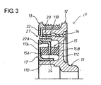
- FIG. 3 shows a torque fluctuation damper pulley 10 in the second embodiment according to the present invention.
- the torque fluctuation damper pulley 10 differs from that in the foregoing first embodiment in a respect that the journal bearing 20 is interposed between the internal surface of the hub portion 11 B of the hub 11 and the external surface of the horizontal portion 22A of the pulley member 13 so that the pulley member 13 can be rotationally carried by the hub 11 directly.
- the pulley member 13 is kept sandwiched between the portions 11C, 17A of the hub 11 under the equal elastic forces from the front and rear.
- the pair of rubber members 15A, 15B may not be of the same thickness in a strict sense and may be suffice to be of those capable of sandwiching the pulley member 13 with equal forces from the front and rear in the axial direction.
- the press fit ring 17 having the vertical wall portion 17A to take the L-letter shape in section is press-fitted on the horizontal wall portion 11 D of the hub 11 in order to sandwich the pair of rubber members 15A, 15B from the front and rear in the axial direction.
- the configuration for sandwiching the rubber members 15A, 15B is not limited to that described above and may take various forms.
- the torque fluctuation damping elastic member 15 sandwiches the pulley member 13 between the portions 11C, 17A of the hub 11 through the pair of rubber members 15A, 15B from the front and rear in the axial direction to joint the pulley member 13 with the hub 11 elastically.
- any thrust bearing which would otherwise be required for positioning the pulley member 13 in the axial direction becomes unnecessary, so that it can be realized to reduce the number of component parts of the torque fluctuation damper pulley 10.
- the pair of rubber members 15A, 15B of the torque fluctuation damping elastic member 15 are composed of those of the same thickness in the axial direction of the pulley member 13, the same can always be kept elastically under equal forces from the front and rear in the axial direction only by sandwiching the pulley member 13 between the portions 11C, 17A of the hub 11 through the rubber members 15A, 15B of the same thickness from the front and rear in the axial direction. Therefore, in addition to the reduction in number of the component parts, it can be realized to enhance the durability of the torque fluctuation damping elastic member 15.
- the pulley member 13 is rotationally carried in radial directions by the journal bearing 20 which is interposed between itself and either one of the inertia mass 12 and the hub 11, it can be realized to support the pulley member 13 at a radial position where the rotational center of the pulley member 13 precisely coincides with that of the rotational shaft such as crankshaft, irrespective of a change in the tension force of the belt wound around the pulley member 13.
- the support portion 24 formed on the pulley member 13 is made to extend at the intermediate position in the axial direction between the connection portion 11C and the vertical wall portion 17A provided on the hub 11, and the pair of rubber members 15A, 15B of the same thickness are securely adhered respectively between one axial end of the support portion 24 and the connection portion 11C and between the other axial end of the support portion 24 and the vertical wall portion 17A. Therefore, it can be realized in a simplified construction to elastically keep the pulley member 13 always under equal forces from the front and rear in the axial direction.
- the torque fluctuation damper pulley 10 is provided with a torque fluctuation damping elastic member 15 between a hub 11 attached to a rotational shaft and a pulley member 13.
- the torque fluctuation damping elastic member 15 includes a pair of rubber members 15A and 15B which sandwich a support portion 24 of the pulley member 13 under equal elastic forces from the front and rear in the axial direction of the pulley member 13 to joint the hub with the pulley member 13 elastically.
- the pulley member 13 always has equal forces being applied thereto from the front and rear in the axial direction, so that it becomes possible to make unnecessary any thrust bearing which would otherwise be required for positioning the pulley member 13 in the axial direction.
Landscapes
- Engineering & Computer Science (AREA)
- General Engineering & Computer Science (AREA)
- Mechanical Engineering (AREA)
- Pulleys (AREA)
Claims (4)
- Poulie d'amortissement des fluctuations du couple comprenant:un moyeu (11) adapté pour être fixé à un arbre de rotation;une masse inertielle (12) prévue autour du moyeu (11);un organe élastique de torsion (14) raccordant la masse inertielle (12) à la surface circonférentielle du moyeu (11);un organe (13) de la poulie rotatif par rapport à la masse inertielle (12); etun organe (15) élastique d'amortissement des fluctuations du couple raccordant élastiquement l'organe (13) de la poulie au moyeu (11);caractérisée en ce que
ledit organe (15) élastique d'amortissement des fluctuations du couple comporte une paire d'organes en caoutchouc (15A, 15B) ce qui amène le moyeu (11) à prendre l'organe (13) de la poulie en tenaille entre des forces élastiques égales provenant de l'avant et de l'arrière dans la direction axiale; et
la paire d'organes en caoutchouc (15A, 15B) sont composés d'organes en caoutchouc qui ont la même épaisseur dans la direction axiale. - Poulie d'amortissement des fluctuations du couple selon la revendication 1, dans laquelle l'organe (13) de la poulie est porté en rotation dans des directions radiales par un palier lisse (20) interposé entre lui-même et l'un parmi la masse inertielle (12) et le moyeu (11).
- Poulie d'amortissement des fluctuations du couple selon la revendication 1 ou 2, dans lequel le moyeu (11) comporte:une portion de bosse cylindrique (11A);une portion de moyeu cylindrique (11B) prévue autour de la portion de bosse (11A) de manière coaxiale;une portion de raccordement (11C) s'étendant radialement et raccordant la portion de moyeu (11B) à la portion de bosse (11A); etune portion (11D) de paroi horizontale cylindrique faisant saillie depuis la portion de bosse (11A) et s'étendant parallèlement à la portion de moyeu (11B), où la poulie d'amortissement des fluctuations du couple comprend en plus:un anneau (17) à ajustement avec serrage ajusté de force sur la portion (11D) de paroi horizontale et ayant une portion (17A) de paroi verticale regardant la portion de raccordement dans la direction axiale; etune portion de soutien (24) s'étendant radialement de manière rentrante depuis l'organe (13) de la poulie au niveau d'une position intermédiaire dans la direction axiale entre la portion de raccordement (11C) et la portion (17A) de paroi verticale; et où la paire d'organes en caoutchouc (15A, 15B) de la même épaisseur sont fixés respectivement entre une extrémité axiale de la portion de soutien (24) et la portion de raccordement (11C) et entre l'autre extrémité axiale de la portion de soutien (24) et la portion (17A) de paroi verticale.
- Poulie d'amortissement des fluctuations du couple selon la revendication 3, dans lequel:l'organe (13) de la poulie comporte une surface d'extrémité (22) s'étendant radialement en parallèle à la portion de raccordement (11C) et ayant au moins un trou (25) d'engagement arqué s'étendant dans la direction circonférentielle; etla portion de moyeu (11B) présente au moins une protubérance d'engagement (26) devant être insérée sans serrage dans le trou (25) d'engagement arqué au moins avec un jeu au niveau de chaque côté correspondant dans la direction circonférentielle.
Applications Claiming Priority (1)
| Application Number | Priority Date | Filing Date | Title |
|---|---|---|---|
| JP2005147616A JP4572739B2 (ja) | 2005-05-20 | 2005-05-20 | 回転変動吸収ダンパプーリ |
Publications (2)
| Publication Number | Publication Date |
|---|---|
| EP1724496A1 EP1724496A1 (fr) | 2006-11-22 |
| EP1724496B1 true EP1724496B1 (fr) | 2009-12-02 |
Family
ID=36603359
Family Applications (1)
| Application Number | Title | Priority Date | Filing Date |
|---|---|---|---|
| EP06114080A Expired - Fee Related EP1724496B1 (fr) | 2005-05-20 | 2006-05-17 | Poulie avec élément d'amortissement pour l'amortissement de variations de couple |
Country Status (4)
| Country | Link |
|---|---|
| US (1) | US7850557B2 (fr) |
| EP (1) | EP1724496B1 (fr) |
| JP (1) | JP4572739B2 (fr) |
| DE (1) | DE602006010761D1 (fr) |
Families Citing this family (33)
| Publication number | Priority date | Publication date | Assignee | Title |
|---|---|---|---|---|
| ITTO20020622A1 (it) * | 2002-07-16 | 2004-01-16 | Dayco Europe Srl | Gruppo integrato puleggia-smorzatore torsionale |
| JP4391990B2 (ja) * | 2003-07-11 | 2009-12-24 | 株式会社フコク | アイソレーション・ダンパプーリおよびその製造方法 |
| GB2433972A (en) * | 2006-01-05 | 2007-07-11 | Metaldyne Internat France Sas | A torsional isolation device for isolating torque fluctuations |
| JP2008144827A (ja) * | 2006-12-08 | 2008-06-26 | Fukoku Co Ltd | ダンパ付プーリ |
| US8740735B2 (en) * | 2007-02-15 | 2014-06-03 | Dayco Europe S.R.L. | Damper pulley assembly having a safety device |
| JP4435810B2 (ja) * | 2007-06-26 | 2010-03-24 | 三ツ星ベルト株式会社 | プーリ構造体、及び、これを用いた補機駆動システム |
| EP2392834A1 (fr) | 2010-06-03 | 2011-12-07 | JTEKT Corporation | Équilibreur harmonique |
| KR20120039378A (ko) * | 2010-10-15 | 2012-04-25 | 현대자동차주식회사 | 차량용 댐퍼 풀리 |
| DE112013002418B4 (de) * | 2012-05-08 | 2021-01-21 | Hanon Systems | Kompressorriemenscheibenbaugruppe und Verfahren zur Herstellung derselben |
| US8888622B2 (en) * | 2012-06-04 | 2014-11-18 | The Gates Corporation | Isolator decoupler |
| US20150285312A1 (en) * | 2012-10-12 | 2015-10-08 | Litens Automotive Partnership | Isolator for use with mgu that is used to assist or start engine through and endless drive member |
| DE102012024958A1 (de) * | 2012-12-20 | 2014-07-10 | GM Global Technology Operations LLC (n. d. Ges. d. Staates Delaware) | Riemenscheibe für eine Kurbelwelle in einem Fahrzeug |
| US9273773B2 (en) * | 2013-03-15 | 2016-03-01 | Magna Powertrain, Inc. | One-piece inertia ring and method of manufacturing the one-piece inertia ring |
| US9599209B2 (en) * | 2014-03-05 | 2017-03-21 | Dayco Ip Holdings, Llc | Torsional vibration dampers |
| US9476497B2 (en) * | 2014-04-23 | 2016-10-25 | Ningbo Yangtong Automobile Parts Co., Ltd | Unidirectional clutch decoupling device for transferring torque between belt wheel and shaft |
| US9600999B2 (en) | 2014-05-21 | 2017-03-21 | Universal City Studios Llc | Amusement park element tracking system |
| EP3152458B1 (fr) | 2014-06-09 | 2021-01-13 | Dayco IP Holdings, LLC | Amortisseur de vibrations de torsion doté d'un isolateur verrouillé |
| US10030757B2 (en) * | 2014-07-01 | 2018-07-24 | Dayco Ip Holdings, Llc | Torsional vibration damper with an interlocked isolator |
| JP6782699B2 (ja) * | 2014-09-02 | 2020-11-11 | デイコ アイピー ホールディングス, エルエルシーDayco Ip Holdings, Llc | 二重弾性部材を有する捩れ振動ダンパ |
| JP2017531768A (ja) * | 2014-10-14 | 2017-10-26 | デイコ アイピー ホールディングス, エルエルシーDayco Ip Holdings, Llc | ねじれ振動ダンパー |
| US9291253B1 (en) | 2015-03-24 | 2016-03-22 | Gates Corporation | Isolating decoupler |
| KR101714208B1 (ko) * | 2015-09-03 | 2017-03-08 | 현대자동차주식회사 | 개별 회전 관성질량을 갖춘 토셔널 댐퍼와 이를 적용한 크랭크샤프트 |
| WO2017070839A1 (fr) * | 2015-10-27 | 2017-05-04 | 深圳市兆威机电有限公司 | Réducteur à engrenage et son mécanisme de liaison d'engrenage |
| US20180369823A1 (en) * | 2015-12-18 | 2018-12-27 | Sandvik Intellectual Property Ab | Torque reaction pulley for an inertia cone crusher |
| US20190085934A1 (en) * | 2017-09-21 | 2019-03-21 | Optimized Solutions, LLC | Torsional vibration damper with low elastomer content |
| JP6811702B2 (ja) * | 2017-12-19 | 2021-01-13 | Nok株式会社 | トーショナルダンパ |
| US11549558B2 (en) | 2018-08-01 | 2023-01-10 | Gates Corporation | Isolator decoupler |
| US11732774B2 (en) * | 2018-09-10 | 2023-08-22 | Litens Automotive Partnership | Combined isolation and torsional vibration damping device |
| DE102019102759A1 (de) * | 2019-02-05 | 2020-08-06 | Schaeffler Technologies AG & Co. KG | Riemenscheibe mit Torsionsschwingungsdämpfereinrichtung (TSD) |
| DE102020127092A1 (de) * | 2020-09-08 | 2022-03-10 | Schaeffler Technologies AG & Co. KG | Riemenscheibenentkoppler mit an einem Nabenbestandteil angebundenen Trägerblech eines Schwingungstilgers |
| CN114483878B (zh) * | 2020-11-11 | 2023-08-01 | 宇通客车股份有限公司 | 一种电动客车及其扭转减振装置 |
| US11796046B2 (en) * | 2021-01-08 | 2023-10-24 | American Axle & Manufacturing, Inc. | Isolated drive assembly with an isolator assembly and a torque limiter for limiting the transmission of torque through an elastomeric element of the isolator assembly |
| CN118043569A (zh) * | 2022-01-07 | 2024-05-14 | Nok株式会社 | 扭转阻尼器 |
Family Cites Families (30)
| Publication number | Priority date | Publication date | Assignee | Title |
|---|---|---|---|---|
| US2204953A (en) * | 1937-01-11 | 1940-06-18 | Nat Malleable & Steel Castings | Resilient car wheel |
| US2674897A (en) * | 1949-06-11 | 1954-04-13 | S D M Company | Resilient sheave |
| US2672907A (en) * | 1952-05-22 | 1954-03-23 | Enjar Wheels Ltd | Resilient wheel |
| FR1496200A (fr) * | 1966-08-17 | 1967-09-29 | Luxembourg Brev Participations | Perfectionnements apportés aux accouplements élastiques |
| GB1203999A (en) * | 1967-11-03 | 1970-09-03 | Holset Engineering Co | Torsional vibration damper |
| US4041803A (en) * | 1975-12-01 | 1977-08-16 | Caterpillar Tractor Co. | Rubber torsional vibration damper with cooling means |
| US4378865A (en) * | 1980-12-10 | 1983-04-05 | Houdaille Industries, Inc. | Rubber and viscous/rubber torsional dampers and method of making the same |
| JPS61211552A (ja) * | 1985-03-13 | 1986-09-19 | Toyota Motor Corp | 車輌のクランクダンパプ−リ構造 |
| JPH07117312B2 (ja) | 1989-06-14 | 1995-12-18 | シャープ株式会社 | 多室型冷暖房装置 |
| DE4018596A1 (de) | 1990-06-09 | 1991-12-19 | Freudenberg Carl Fa | Drehelastische kupplung |
| JPH04249635A (ja) * | 1990-12-28 | 1992-09-04 | Tokai Rubber Ind Ltd | デュアルタイプダンパー |
| US5452622A (en) * | 1993-02-09 | 1995-09-26 | Magi, L.P. | Stress dissipation gear |
| DE4320938C2 (de) * | 1993-06-24 | 1995-05-24 | Freudenberg Carl Fa | Elastische Kupplung |
| US5405296A (en) * | 1993-12-28 | 1995-04-11 | Tesma International Inc. | Torsional vibration damper |
| FR2730782B1 (fr) | 1995-02-17 | 1997-04-25 | Dampers | Dispositif d'entrainement comportant un amortisseur de vibrations de torsion |
| US6332842B1 (en) * | 1999-06-21 | 2001-12-25 | Denso Corporation | Rotation transmitter having torque limiting mechanism |
| JP2001159448A (ja) * | 1999-11-30 | 2001-06-12 | Fukoku Co Ltd | アイソレーション・ダンパプーリ |
| DE10059101B4 (de) * | 2000-11-28 | 2012-12-20 | Zf Friedrichshafen Ag | Antriebssystem |
| GB2374654A (en) | 2001-04-04 | 2002-10-23 | Metaldyne Internat | Torsional vibration damper |
| ITTO20010739A1 (it) | 2001-07-26 | 2003-01-26 | Diantel Corp N V | Gruppo di puleggia, particolarmente per un motore a combustione interna. |
| JP3915486B2 (ja) * | 2001-11-26 | 2007-05-16 | 株式会社デンソー | トルク伝達装置 |
| DE10211640B4 (de) * | 2002-03-15 | 2005-03-24 | Carl Freudenberg Kg | Drehelastische Kupplung |
| JP2003343652A (ja) | 2002-05-23 | 2003-12-03 | Nok Corp | トルク変動吸収ダンパ |
| JP2004144253A (ja) | 2002-10-28 | 2004-05-20 | Nok Corp | トルク変動吸収ダンパ |
| JP2004278618A (ja) | 2003-03-14 | 2004-10-07 | Nok Corp | トルク変動吸収ダンパ |
| JP2004278726A (ja) | 2003-03-18 | 2004-10-07 | Nok Corp | トルク変動吸収ダンパ |
| JP4314561B2 (ja) | 2003-04-17 | 2009-08-19 | 株式会社フコク | アイソレーション・ダンパプーリ |
| JP2004340169A (ja) | 2003-05-13 | 2004-12-02 | Nok Corp | トルク変動吸収ダンパ |
| JP4391990B2 (ja) * | 2003-07-11 | 2009-12-24 | 株式会社フコク | アイソレーション・ダンパプーリおよびその製造方法 |
| JP4231751B2 (ja) | 2003-08-08 | 2009-03-04 | 株式会社ニフコ | 燃料タンク用ストレーナ装置 |
-
2005
- 2005-05-20 JP JP2005147616A patent/JP4572739B2/ja not_active Expired - Fee Related
-
2006
- 2006-05-16 US US11/434,178 patent/US7850557B2/en not_active Expired - Fee Related
- 2006-05-17 DE DE602006010761T patent/DE602006010761D1/de active Active
- 2006-05-17 EP EP06114080A patent/EP1724496B1/fr not_active Expired - Fee Related
Also Published As
| Publication number | Publication date |
|---|---|
| DE602006010761D1 (de) | 2010-01-14 |
| JP4572739B2 (ja) | 2010-11-04 |
| JP2006322573A (ja) | 2006-11-30 |
| US20060264282A1 (en) | 2006-11-23 |
| EP1724496A1 (fr) | 2006-11-22 |
| US7850557B2 (en) | 2010-12-14 |
Similar Documents
| Publication | Publication Date | Title |
|---|---|---|
| EP1724496B1 (fr) | Poulie avec élément d'amortissement pour l'amortissement de variations de couple | |
| US6582312B2 (en) | Torque fluctuation absorbing apparatus having structure for reducing misalignment of torque limiter during assembling thereof, and method for assembling the same | |
| US20060144664A1 (en) | Crankshaft torque modulator | |
| US7412913B2 (en) | Apparatus for driving an oil pump for automatic transmission | |
| US6955252B2 (en) | Device for isolating torque fluctuations | |
| EP3152458B1 (fr) | Amortisseur de vibrations de torsion doté d'un isolateur verrouillé | |
| JP2007506056A (ja) | クランクシャフトデカプラー | |
| US10190654B2 (en) | Apparatus for a drive system having a cartridge housing one or more elastomer members | |
| US20150198207A1 (en) | Friction clutch plate with damping springs | |
| CN110352312B (zh) | 变矩器 | |
| US10100914B2 (en) | Gear | |
| US20220213954A1 (en) | Decoupler | |
| GB2382395A (en) | A device for isolating fluctuations in the drive torque of a rotary drive shaft | |
| JPH08177874A (ja) | ねじり振動ダンパー一体型ねじり弾性継手 | |
| JP2004108528A (ja) | トルク変動吸収ダンパ | |
| JP4006582B2 (ja) | トルク変動吸収ダンパ | |
| JP4479903B2 (ja) | トルク変動吸収ダンパ | |
| JP2003254388A (ja) | トルク変動吸収ダンパ | |
| JP2004116640A (ja) | トルク変動吸収ダンパ | |
| KR102340618B1 (ko) | 듀얼 매스 플라이휠 | |
| JPH1130299A (ja) | 可変径プーリ | |
| CN120265901A (zh) | 具有用于界定减振器内部空间的贴靠元件的扭振减振器 | |
| US20080171623A1 (en) | Structure of belt driven mechanism designed to ensure stability of operation of bearing | |
| JP2001355678A (ja) | トルク変動吸収ダンパ | |
| GB2374654A (en) | Torsional vibration damper |
Legal Events
| Date | Code | Title | Description |
|---|---|---|---|
| PUAI | Public reference made under article 153(3) epc to a published international application that has entered the european phase |
Free format text: ORIGINAL CODE: 0009012 |
|
| AK | Designated contracting states |
Kind code of ref document: A1 Designated state(s): AT BE BG CH CY CZ DE DK EE ES FI FR GB GR HU IE IS IT LI LT LU LV MC NL PL PT RO SE SI SK TR |
|
| AX | Request for extension of the european patent |
Extension state: AL BA HR MK YU |
|
| 17P | Request for examination filed |
Effective date: 20070420 |
|
| AKX | Designation fees paid |
Designated state(s): DE |
|
| 17Q | First examination report despatched |
Effective date: 20070703 |
|
| GRAP | Despatch of communication of intention to grant a patent |
Free format text: ORIGINAL CODE: EPIDOSNIGR1 |
|
| GRAS | Grant fee paid |
Free format text: ORIGINAL CODE: EPIDOSNIGR3 |
|
| GRAA | (expected) grant |
Free format text: ORIGINAL CODE: 0009210 |
|
| AK | Designated contracting states |
Kind code of ref document: B1 Designated state(s): DE |
|
| REF | Corresponds to: |
Ref document number: 602006010761 Country of ref document: DE Date of ref document: 20100114 Kind code of ref document: P |
|
| PLBE | No opposition filed within time limit |
Free format text: ORIGINAL CODE: 0009261 |
|
| STAA | Information on the status of an ep patent application or granted ep patent |
Free format text: STATUS: NO OPPOSITION FILED WITHIN TIME LIMIT |
|
| 26N | No opposition filed |
Effective date: 20100903 |
|
| PGFP | Annual fee paid to national office [announced via postgrant information from national office to epo] |
Ref country code: DE Payment date: 20130515 Year of fee payment: 8 |
|
| REG | Reference to a national code |
Ref country code: DE Ref legal event code: R119 Ref document number: 602006010761 Country of ref document: DE |
|
| REG | Reference to a national code |
Ref country code: DE Ref legal event code: R119 Ref document number: 602006010761 Country of ref document: DE Effective date: 20141202 |
|
| PG25 | Lapsed in a contracting state [announced via postgrant information from national office to epo] |
Ref country code: DE Free format text: LAPSE BECAUSE OF NON-PAYMENT OF DUE FEES Effective date: 20141202 |