EP1724980A2 - OFDM Empfangsmethode und Empfangsgerät - Google Patents
OFDM Empfangsmethode und Empfangsgerät Download PDFInfo
- Publication number
- EP1724980A2 EP1724980A2 EP05021199A EP05021199A EP1724980A2 EP 1724980 A2 EP1724980 A2 EP 1724980A2 EP 05021199 A EP05021199 A EP 05021199A EP 05021199 A EP05021199 A EP 05021199A EP 1724980 A2 EP1724980 A2 EP 1724980A2
- Authority
- EP
- European Patent Office
- Prior art keywords
- decoding
- processing
- iterations
- interference
- signal
- Prior art date
- Legal status (The legal status is an assumption and is not a legal conclusion. Google has not performed a legal analysis and makes no representation as to the accuracy of the status listed.)
- Withdrawn
Links
Images






Classifications
-
- H—ELECTRICITY
- H04—ELECTRIC COMMUNICATION TECHNIQUE
- H04L—TRANSMISSION OF DIGITAL INFORMATION, e.g. TELEGRAPHIC COMMUNICATION
- H04L25/00—Baseband systems
- H04L25/02—Details ; arrangements for supplying electrical power along data transmission lines
- H04L25/03—Shaping networks in transmitter or receiver, e.g. adaptive shaping networks
- H04L25/03006—Arrangements for removing intersymbol interference
- H04L25/03178—Arrangements involving sequence estimation techniques
- H04L25/03248—Arrangements for operating in conjunction with other apparatus
- H04L25/03286—Arrangements for operating in conjunction with other apparatus with channel-decoding circuitry
-
- H—ELECTRICITY
- H04—ELECTRIC COMMUNICATION TECHNIQUE
- H04L—TRANSMISSION OF DIGITAL INFORMATION, e.g. TELEGRAPHIC COMMUNICATION
- H04L25/00—Baseband systems
- H04L25/02—Details ; arrangements for supplying electrical power along data transmission lines
- H04L25/03—Shaping networks in transmitter or receiver, e.g. adaptive shaping networks
- H04L25/03006—Arrangements for removing intersymbol interference
- H04L25/03012—Arrangements for removing intersymbol interference operating in the time domain
- H04L25/03019—Arrangements for removing intersymbol interference operating in the time domain adaptive, i.e. capable of adjustment during data reception
-
- H—ELECTRICITY
- H04—ELECTRIC COMMUNICATION TECHNIQUE
- H04L—TRANSMISSION OF DIGITAL INFORMATION, e.g. TELEGRAPHIC COMMUNICATION
- H04L27/00—Modulated-carrier systems
- H04L27/26—Systems using multi-frequency codes
- H04L27/2601—Multicarrier modulation systems
- H04L27/2647—Arrangements specific to the receiver only
Definitions
- This invention relates to an OFDM receiving method and apparatus. More particularly, the invention relates to an OFDM receiving method and apparatus for receiving a signal that has sustained inter-symbol interference owing to delayed waves that exceed a guard interval, eliminating at least inter-symbol interference from the receive signal and applying demodulation and decoding processing to the receive signal from which interference has been eliminated.
- OFDM Orthogonal Frequency Division Multiplex
- a guard interval GI is inserted in order to eliminate inter-symbol interference (ISI) ascribable to multipath.
- Fig. 9 is a diagram useful in describing inter-symbol interference due to delayed waves, where A represents a direct wave and B a delayed wave (reflected wave).
- delay time ⁇ of delayed wave B is less than a guard-interval length N G , as indicated at (a) in Fig. 9, then a data symbol D 0 of direct wave A will not overlap other data symbols of delayed wave B in a window timing W and inter-symbol interference will not occur.
- delay time ⁇ of delayed wave B is greater than the guard-interval length N G , as indicated at (b) in Fig. 9, data symbol D 0 of direct wave A will overlap another data symbol D -1 of delayed wave B in the window timing W and inter-symbol interference will occur. Accordingly, maximum delay time ⁇ MAX of the delayed wave is taken into account and the guard-interval length N G is decided in such a manner that ISI will not occur.
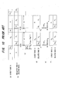
- Fig. 10 is a diagram useful in describing ISI elimination.
- a delayed wave B lags behind a direct wave A by the GI length N G or more, and the delay time N ⁇ max satisfies the relation N G ⁇ N ⁇ max .
- the data symbol D 0 of the direct wave A partially overlaps a pilot symbol P of the delayed wave B and sustains ISI from the pilot symbol P of the delayed wave B. It is necessary, therefore, to remove this portion [see,the hatched portion at (d) of Fig. 10] of the pilot symbol from the receive signal.
- the y portion is cut out of the already known pilot-signal waveform and is generated as an ISI replica RPp [see the hatched portion at (e) of Fig. 10].
- the ISI replica RPp is subtracted from the receive signal [see the left side at (f) of Fig. 10].
- the portion of the delayed wave that interferes with the direct wave can be made zero and it is possible to eliminate ISI interference. That is, by applying FFT processing to the signal at (f) of Fig. 10, OFDM demodulation that will not be affected by ISI becomes possible.
- a data symbol D 1 (see Fig.
- the time over which ISI interference is received (the number of samples) is y. Accordingly, the y portion is cut out of the time waveform of the preceding data symbol D 0 and is generated as an ISI replica RP 0 [see the hatched portion at (e) of Fig. 10]. The ISI replica RP 0 is subtracted from the receive signal [see the right side at (f) of Fig. 10].
- the portion of the delayed wave that interferes with the direct wave can be made zero and it is possible to eliminate ISI interference. That is, by applying FFT processing to the signal at (f) of Fig. 10, OFDM demodulation that will not be affected by ISI becomes possible.
- Fig. 11 is a diagram useful in describing elimination of ICI.
- the portion of the ISI segment y of the delayed wave B shown at (a) of Fig. 11 is eliminated, thereby generating the receive signal indicated at (b), and this signal is subjected to FFT processing to eliminate inter-symbol interference ISI.
- the delayed wave B becomes discontinuous at the portion of the ISI segment y.
- the waveform is no longer periodic. Consequently, each subcarrier component obtained by FFT processing includes distortion ascribable to inter-carrier interference ICI.
- the receive signal at (b) of Fig. 11 is subjected to FFT processing, as shown at (d) of Fig. 11, after which IFFT processing is applied, thereby providing a continuous signal waveform, as shown at (e) of Fig. 11. If the tail-end segment y of the continuous signal waveform at (e) of Fig. 11 is cut out and inserted into the segment y at the front end of the receive signal at (b) of Fig.
- the delayed wave B will become a continuous periodic waveform, as shown at (f) of Fig. 11. If FFT processing is applied to the signal at (f) of Fig. 11, ICI is suppressed. It should be noted that, ideally, it is necessary for the delayed wave B shown at (f) of Fig. 11 to be made a continuous periodic waveform by the waveform at (e) of Fig. 11. However, since the waveform at (b) of Fig. 11 is subjected to FTT and IFFT processing, the waveform at (e) of Fig. 11 departs slightly from the ideal shape.
- Fig. 12 is a block diagram of an OFDM receiver for applying OFDM demodulation processing to a signal that has undergone ISI and ICI removal, subjecting the demodulated signal obtained to decoding processing and outputting the decoded signal.
- a GI removing unit 100 removes the GI from the receive signal, and a pilot/data separating unit 101 separates data and a pilot from the receive signal, inputs the data to an ISI replica generating/eliminating unit 102 and inputs the pilot to a delay profile generator 103.
- the delay profile generator 103 calculates the correlation between the receive pilot signal and the already known pilot signal and outputs a delay profile.
- An ISI replica generator 102a adopts, from the delay profile, a delay-time portion greater than the guard-interval length NG as an ISI portion and generates, as an ISI replica, a time-waveform portion of the already known symbol (pilot symbol), which conforms to the ISI portion, or a time-waveform portion of the preceding symbol [see (e) of Fig. 10].
- a channel compensator 102b multiplies the ISI replica by a channel estimation value, thereby applying channel compensation, and inputs the result to a subtractor 102c. The latter subtracts the ISI replica from the receive signal and inputs the direct wave A and delayed wave B (data symbol D 0 ), which are shown on the left side at (f) of Fig.
- the FFT processor 104 applies FFT processing to the receive signal input thereto, thereby generating data elements on a per-subcarrier basis.
- An FFT processor 105 applies FFT processing to the channel estimation value, thereby generating a channel compensation value for each subcarrier.
- a channel compensator 106 multiplies the result of FFT processing by a channel compensation value subcarrier by subcarrier, demodulates data elements of the number of subcarriers that constitute the data symbol D 0 and inputs the result to a replica generating / ICI eliminating unit 107.
- the replica generating / ICI eliminating unit 107 has an IFFT processor 107a which applies IFFT processing to the demodulated data of the number of subcarriers constituting the data symbol D 0 output from the channel compensator 106 and outputs the time-waveform signal [see (e) of Fig. 11] of data symbol D 0 .
- a demodulated-signal restoration replica generator 107b cuts out the signal portion of the y segment [see (e) of Fig. 11] at the tail end of the time-waveform signal that enters from the IFFT processor 107a, thereby generating a demodulated-signal restoration replica (ICI replica), and inputs the replica to a combiner 107c.
- the latter adds the demodulated-signal restoration replica to the receive signal [see (d) of Fig. 11] that is output from the subtractor 102c, thereby producing a continuous signal waveform, and inputs this waveform to an FFT processor 108a of an OFDM demodulator 108.
- the FFT arithmetic unit 108a applies FFT processing to the combined signal that is output from the combiner 107c, thereby generating data elements on a per-subcarrier basis.
- a channel compensator 108b multiplies the result of FFT processing by the channel compensation value subcarrier-by-subcarrier and outputs the result of channel estimation as a decoded signal.
- a decoding processor 109 applies error-correcting decoding processing to OFDM-demodulated data (soft-decision data) and outputs the decoded result (hard-decision data).
- error-correcting code examples include a turbo code, which is capable of implementing an error characteristic near the Shannon limit, and a low-density parity check (LDPC: Low Density Parity Check) code.
- a method of improving the error characteristic by updating a priori probability of each receive bit stream of a code word, which has been obtained prior to decoding processing, to a value having a high probability through iterative decoding is used as the decoding method in these error-correcting codes.
- An error-correcting encoder 110 encodes the result of decoding processing, and an IFFT processor 111 applies IFFT processing to the decoded data of the number of subcarriers that constitute the encoded data symbol D 0 and outputs the time-waveform signal of the data symbol D 0 .
- a delay circuit 112 delays this time-waveform signal by a time equivalent to one symbol time T s and inputs the delayed signal to the ISI replica generator 102a.
- a data symbol D 1 (see Fig. 10) of the direct wave A partially overlaps the preceding data symbol D 0 of the delayed wave B and sustains ISI from the data symbol D 0 of the delayed wave B. It is necessary, therefore, to remove this portion of the data symbol D 0 from the receive signal.
- the time (number of samples) subjected to ISI is y. Accordingly, the ISI replica generator 102a cuts the y portion out of the time-waveform signal (the output signal of the delay circuit 112) of the previous data symbol D 0 to generate it as the ISI replica [see the hatched portion at (e) of Fig. 10].
- the channel compensator 102b multiplies the ISI replica by the channel estimation value, thereby applying channel compensation, and inputs the result to the subtractor 102c.
- the latter subtracts the ISI replica from the receive signal and inputs the direct wave A and delayed wave B (data symbol D 1 ), which are shown on the right side at (f) of Fig. 10, to the FFT processor 104, which is the next stage. Thenceforth, and in similar fashion, processing is executed in a manner similar to that of data symbol D 0 .
- the BER (Bit Error Rate) characteristic can be improved by eliminating ISI and ICI.
- turbo equalization processing namely replica generation, ISI and ICI removal, demodulation and decoding
- an excellent transmission characteristic can be implemented even in a multipath environment in which the GI length is exceeded.
- code is a turbo code and LDPC code
- an object of the present invention is to perform decoding processing using a combination, which will provide the optimum reception characteristic, among combinations of numbers of turbo equalization iterations and numbers of decoding iterations for which receive processing will be completed within a stipulated period of time.
- Another object of the present invention is to perform decoding processing upon changing over to a combination that will give the optimum reception characteristics in accordance with a change in the propagation path.
- the foregoing objects are attained by providing an OFDM receiving method and apparatus for receiving a signal that has sustained inter-symbol interference owing to a delayed wave that exceeds a guard interval.
- a step of eliminating at least inter-symbol interference from the receive signal, a step of applying demodulation and decoding processing to the receive signal from which interference has been eliminated, and step of changing over the OFDM receiving method of the present invention comprises a step of eliminating at least inter-symbol interference from the receive signal, a step of applying demodulation and decoding processing to the receive signal from which interference has been eliminated, and step of changing over a combination of number of iterations of equalization processing for eliminating interference from the receive signal and for demodulating and decoding the receive signal and number of iterations for repeating the decoding in the decoding processing, based upon the state of the propagation path.
- SIR which is the ratio of the desired signal power to interference power is utilized as said state of the propagation path. More specifically, a corresponding relationship between combinations of numbers of iterations of the equalization processing and numbers of iterations of the decoding and SIRs is set in advance, and the number of iterations of the equalization processing and number of iterations of the decoding are decided using this corresponding relationship.
- a combination of number of iterations of the equalization processing and number of iterations of the decoding is obtained in such a manner that the equalization processing of the number of iterations will be completed within a set processing time, and the corresponding relationship between each combination and SIR is set so as to optimize the reception characteristic.
- An OFDM receiving apparatus comprises an interference eliminating unit for eliminating at least inter-symbol interference from a receive signal; a demodulation processing unit for applying demodulation processing to the receive signal from which interference has been eliminated; a decoding processing unit for applying error-correcting decoding processing to the demodulated signal; and an iteration controller for deciding, based upon state of a propagation path, a combination of number of iterations of equalization processing for eliminating interference from the receive signal and for demodulating and decoding the receive signal, and number of iterations for repeating the decoding in the decoding processing.
- a SIR estimation unit estimates SIR, which is the ratio of the desired signal to interference power, as state of the propagation path using an impulse response group of the propagation path with respect to an OFDM symbol group.
- SIR the ratio of the desired signal to interference power
- a combination of number of iterations of equalization processing and number of iterations of decoding is obtained in such a manner that equalization processing of the number of iterations will be completed within a set processing time, and the corresponding relationship between each combination and SIR is set so as to optimize the reception characteristic.
- the optimum decoding processing can be executed using a combination of number of iterations of equalization and number of iterations of decoding such that receive processing will be completed within a stipulated period of time.
- an OFDM receiving method for receiving a signal that has sustained inter-symbol interference owing to a delayed wave that exceeds a guard interval, eliminating at least inter-symbol interference from the receive signal and applying demodulation and decoding processing to the receive signal from which interference has been eliminated, a combination of number of iterations of equalization processing for eliminating interference from the receive signal and demodulating and decoding the receive signal and number of iterations for repeating the decoding in the decoding processing is changed over based upon the state of the propagation path, e.g., the SIR, which is the ratio of the desired signal power to interference power.
- Fig. 1 is a block diagram illustrating the structure of the OFDM receiving apparatus according to the present invention.
- This is a diversity arrangement, in which receive branches #1 to #B are provided for every receive antenna (not shown). It should be noted, however, that a diversity arrangement need not necessarily be adopted.
- Each branch has a GI removing unit 11 for removing the guard interval from the antenna receive signal; a pilot/data separating unit 12 for separating data and a pilot from the signal from which the guard interval has been removed; a channel impulse response estimation unit (CIR estimation unit) 13 for estimating the channel by calculating the correlation between the receive pilot and already known pilot; and an ISI/ICI eliminating unit 14 for eliminating ICI, ISI replicas from the receive signal.
- CIR estimation unit channel impulse response estimation unit
- An OFDM demodulator 15 combines the output signals (the signals from which ISI and ICI have been eliminated) from respective ones of the branches by maximum-ratio combining or some other method, applies demodulation processing to the combined signal and outputs the demodulated signal.
- turbo equalization processing is a series of processes comprising replica generation, ISI and ICI removal, demodulation and decoding.
- a SIR estimation unit 21 estimates, for every encoded block, the SIR based upon the CIR estimation value, receive signal power and interference signal power, and an iteration controller 22 decides the equalization iteration count I EQU and decoding iteration count I DEC based upon the SIR and sets I EQU and I DEC in the selector 17 and decoding processor 16, respectively.
- the GI removing unit 11, pilot/data separating unit 12 and CIR estimation unit 13 correspond to the GI removing unit 100, pilot/data separating unit 101 and delay profile generator 103, respectively, in Fig. 12.
- the ISI/ICI eliminating unit 14 corresponds to the subtractor 102c that eliminates ISI and the combiner 107c that eliminates ICI in Fig. 12
- the OFDM demodulator 15 and decoding processor 16 correspond to the OFDM modulator 108 and decoding processor 109, respectively
- the replica generator 18 corresponds to the replica generator 102a and demodulated-signal restoration replica generator 107b.
- the transmitting side usually multiplexes the pilot signal and inserts the guard intervals before transmission.
- the GI removing unit 11 removes the guard intervals and then the pilot/data separating unit 12 separates the pilot signal [y P,i,b (k)] and data signal [y D,i,b (k)], where i represents the symbol number, b the receive branch number and k the sample point.
- the CIR estimation unit 13 derives a CIR estimation value [ ⁇ i,b ( j )] at a jth sample point in an ith data symbol using the pilot signal y P,1,b (k).
- Equation (1) can be obtained as set forth below. It should be noted that one OFDM symbol is composed of a guard interval GI of N G samples and a data portion (FFT window portion) of N samples, a position from the leading end of one OFDM symbol is expressed by 0 to N+N G enclosed by parentheses [i.e., by (0) to (N+N G )], and a position within the FFT window is expressed by 0 to N-1 not enclosed by parentheses.
- a receive signal y D,i,b (k) at the time of a kth sample of an ith symbol of the direct wave is the total of the signals indicated by the hatching in Fig. 2.
- Equation (1) is obtained.
- Equation (2) is obtained by adding the demodulated-signal restoration replica to the left side of Equation (1) from which ISI has been eliminated.
- the demodulator 15 combines the output signals (the signals from which ISI and ICI have been eliminated) from respective ones of the branches by maximum-ratio combining or some other method, applies FFT processing to the combined signal, thereby generating data elements on a per-subcarrier basis, and thenceforth multiplies the result of FFT processing by a channel compensation value on a per-subcarrier basis and outputs the result of channel compensation as the demodulated signal.
- the SIR estimation unit 21 estimates the SIR for every encoded block (transport block), which is the unit of encoding.
- a SIR estimation value [R SIR (q)] in an OFDM symbol that transmits a qth encoded block is derived employing the following equations using the CIR estimation value ⁇ i,b (j) obtained from the CIR estimation unit 13:
- the iteration controller 22 decides the turbo equalization iteration count I EQU and decoding iteration count I DEC , sets the decoding iteration count I DEC in the decoding processor 16, sets the turbo equalization iteration count I EQU in the selector 17 and executes control so as to execute turbo equalization and decoding processing the set numbers of times.
- the turbo equalization iteration count I EQU and decoding iteration count I DEC are decided as set forth below. If we let T LIMIT represent the time required for receive processing in an actual system, the following equation must be satisfied in order for receive processing to be completed within this processing time: A I EQU + 1 T EQU + I EQU + 1 I DEC T DEC ⁇ T LIMIT where T EQU represents the time required for replica generation, ISI/ICI elimination and OFDM demodulation processing, T DEC the time required to execute decoding processing one time, and A the number of OFDM symbols necessary to transmit one encoding block. Equalization processing is a series of processes comprising replica generation, ISI and ICI removal, demodulation and decoding processing executed I DEC times.
- the time required for replica generation, ISI, ICI removal and demodulation is T EQU
- the time required for decoding processing one time is T DEC
- the time required to execute equalization processing one time is A T EQU + I DEC T DEC and therefore the processing time needed to execute equalization processing (I EQU +1) times is the left side of Equation (6).
- the iteration controller 22 decides the turbo equalization iteration count I EQU and decoding iteration count I DEC from among the combinations that satisfy Equation (6), sets these in the decoding processor 16 and selector 17, respectively, and exercises control (AIC: Adaptive Iteration Control) in such a manner that processing is executed in the number of iterations.
- AIC Adaptive Iteration Control
- R TH (m) ⁇ R TH (m+1) holds. That is, the smaller the value of SIR, the larger the number of iterations of turbo equalization in the combination.
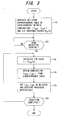
- FIG. 3 illustrates the flow of processing for deciding the turbo equalization iteration count I EQU and decoding iteration count I DEC .
- a correspondence table [the relation indicated by Equation (10)] indicating the correspondence between combinations (I EQU , I DEC ) of turbo equalization iteration count I EQU and decoding iteration count I DEC , which will provide an excellent BLER (Block Error Rate) characteristic, and SIR threshold values R TH (m) is created and stored in advance (step 101).
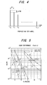
- Table 1 shows simulation parameters, and a propagation path model is illustrated in Fig. 4.
- T LIMIT 8T
- T EQU 0.5T
- T DEC 0.045T
- A 2 hold
- R TH ( 2 ) 8.0
- R TH ( 1 ) 25.0
- the combinations of turbo equalization iteration count I EQU and decoding iteration count I DEC are three in number, namely (4,13), (3,22) and (1,66).
- FIG. 6 illustrates BLER characteristics in a case where AIC and CIC control where carried out when amount of path attenuation ⁇ P was made 0.6, 1.0 and 1.44 in a fading environment.
- a characteristic C is a BLER characteristic of a combination varied by AIC control (a BLER characteristic that prevails when the combination has been changed over depending upon the SIR value) according to the present invention.
- f d T a normalized Doppler frequency
- the present invention is such that optimum iterative control that conforms to the propagation path is carried out in a case where there is a limitation upon processing time in an environment in which multipath delay that exceeds the guard interval exists. In comparison with a case where fixed iterative control is carried out, a better reception characteristic can be obtained.
- the SIR value is estimated and the combinations (I EQU , I DEC ) of turbo equalization iteration count I EQU and decoding iteration count I DEC are decided.
- turbo equalization iteration count I EQU and decoding iteration count I DEC are decided upon estimating a value other than SIR, e.g., error rate or delay spread, etc., as the state of the propagation path.
- a value other than SIR e.g., error rate or delay spread, etc.
- the present invention can be applied to a case where at least ISI is eliminated.
- a diversity arrangement having two or more branches has been' described.
- the present invention can be applied even in a receiving apparatus of a single branch.
- Fig. 7 is a diagram useful in describing a method of deriving Equations (3) to (5).
- j is used in Equations (1) to (5), here complex-number notation is employed and therefore "j" is changed to "x".
- Equation (12) the first term of Equation (12) is signal power within the guard interval, and the second term is signal power that exceeds the guard interval.
- g i , b x 2 and g i , b x 2 N ⁇ x + N G N the reason for this is as follows: If we let 1[
- N*(1/N) 1.
- average power of ICI in the ith symbol becomes 2 g i , b x 2 x ⁇ N G N ⁇ x + N G N 2
- ICI inter-carrier interference
- ISI inter-symbol interference
- interference power of (desired signal power)/[inter-carrier interference (ICI) component + inter-symbol interference (ISI) component].
- ICI inter-carrier interference
- ISI inter-symbol interference
Landscapes
- Engineering & Computer Science (AREA)
- Computer Networks & Wireless Communication (AREA)
- Signal Processing (AREA)
- Power Engineering (AREA)
- Noise Elimination (AREA)
Applications Claiming Priority (1)
| Application Number | Priority Date | Filing Date | Title |
|---|---|---|---|
| JP2005147759A JP4936680B2 (ja) | 2005-05-20 | 2005-05-20 | Ofdm受信方法及び受信装置 |
Publications (2)
| Publication Number | Publication Date |
|---|---|
| EP1724980A2 true EP1724980A2 (de) | 2006-11-22 |
| EP1724980A3 EP1724980A3 (de) | 2012-08-22 |
Family
ID=35520980
Family Applications (1)
| Application Number | Title | Priority Date | Filing Date |
|---|---|---|---|
| EP05021199A Withdrawn EP1724980A3 (de) | 2005-05-20 | 2005-09-28 | OFDM Empfangsmethode und Empfangsgerät |
Country Status (3)
| Country | Link |
|---|---|
| US (1) | US7974372B2 (de) |
| EP (1) | EP1724980A3 (de) |
| JP (1) | JP4936680B2 (de) |
Families Citing this family (26)
| Publication number | Priority date | Publication date | Assignee | Title |
|---|---|---|---|---|
| FI20055715A0 (fi) * | 2005-12-30 | 2005-12-30 | Nokia Corp | Turboekvalisointimenettely |
| JP4425880B2 (ja) * | 2006-01-18 | 2010-03-03 | 株式会社エヌ・ティ・ティ・ドコモ | 通信装置、移動局及び方法 |
| WO2008084784A1 (ja) * | 2007-01-12 | 2008-07-17 | Panasonic Corporation | Ofdm受信装置、ofdm受信集積回路、ofdm受信方法及びofdm受信プログラム |
| US7995688B2 (en) * | 2007-03-08 | 2011-08-09 | Her Majesty The Queen In Right Of Canada, As Represented By The Minister Of Industry, Through The Communications Research Centre Canada | Channel estimation and ICI cancellation for OFDM |
| JP4924201B2 (ja) * | 2007-05-23 | 2012-04-25 | 日本電気株式会社 | 受信品質測定装置および受信品質測定方法 |
| JP4963723B2 (ja) * | 2007-06-19 | 2012-06-27 | シャープ株式会社 | 受信機、受信方法および集積回路 |
| CN101689954A (zh) * | 2007-06-26 | 2010-03-31 | 夏普株式会社 | 接收机以及接收方法 |
| EP2178233A1 (de) * | 2007-08-06 | 2010-04-21 | Sharp Kabushiki Kaisha | Empfänger und empfangsverfahren |
| CN101796754A (zh) * | 2007-09-05 | 2010-08-04 | 夏普株式会社 | 接收机及接收方法 |
| JP2009188640A (ja) * | 2008-02-05 | 2009-08-20 | Sharp Corp | 実行判断装置、受信装置、無線通信システム、及び実行判断方法 |
| JP5084043B2 (ja) * | 2008-06-11 | 2012-11-28 | シャープ株式会社 | 受信装置、通信システム及び通信方法 |
| JP5344121B2 (ja) * | 2008-06-30 | 2013-11-20 | 日本電気株式会社 | シングルキャリア伝送方式における無線通信方法および装置 |
| US7664190B1 (en) * | 2008-08-04 | 2010-02-16 | Mediatek Inc. | Multi-carrier receiver with dynamic power adjustment and method for dynamically adjusting the power consumption of a multi-carrier receiver |
| KR20100070751A (ko) * | 2008-12-18 | 2010-06-28 | 한국전자통신연구원 | 무선 통신 시스템의 채널 추정 방법 및 그 장치 |
| JP2010178273A (ja) * | 2009-02-02 | 2010-08-12 | Sharp Corp | 受信装置及び受信方法 |
| JP5428788B2 (ja) * | 2009-11-13 | 2014-02-26 | シャープ株式会社 | 受信装置、受信方法、及び受信プログラム |
| JP5622404B2 (ja) | 2010-02-22 | 2014-11-12 | シャープ株式会社 | 無線通信システム、および通信装置 |
| JP2011188206A (ja) * | 2010-03-08 | 2011-09-22 | Sharp Corp | 受信装置、受信方法、受信プログラム、及びプロセッサ |
| JP2011234282A (ja) | 2010-04-30 | 2011-11-17 | Sharp Corp | 通信システム、送信装置、受信装置、プログラム、及びプロセッサ |
| JP2012204941A (ja) * | 2011-03-24 | 2012-10-22 | Toshiba Corp | 受信装置および受信方法 |
| JP5724565B2 (ja) * | 2011-04-14 | 2015-05-27 | 日本電気株式会社 | 受信方法及び受信器 |
| CN102868575A (zh) * | 2012-09-24 | 2013-01-09 | 航天科工深圳(集团)有限公司 | 一种电力线载波通信系统的仿真方法、系统 |
| US9608851B2 (en) | 2013-03-15 | 2017-03-28 | Jonathan Kanter | Turbo decoding techniques |
| US9191246B2 (en) | 2013-03-15 | 2015-11-17 | Jonathan Kanter | Combined turbo decoding and turbo equalization techniques |
| US10524161B2 (en) | 2014-08-20 | 2019-12-31 | Qualcomm Incorporated | Delay spread estimation and utilization |
| WO2018098666A1 (zh) * | 2016-11-30 | 2018-06-07 | 华为技术有限公司 | 一种信号接收方法和装置 |
Citations (2)
| Publication number | Priority date | Publication date | Assignee | Title |
|---|---|---|---|---|
| JP2004208254A (ja) | 2002-11-08 | 2004-07-22 | Fujitsu Ltd | Ofdm伝送方式における受信装置 |
| JP2004289475A (ja) | 2003-03-20 | 2004-10-14 | Fujitsu Ltd | Ofdmシンボルを復調する受信機 |
Family Cites Families (8)
| Publication number | Priority date | Publication date | Assignee | Title |
|---|---|---|---|---|
| FI981745A7 (fi) * | 1998-08-12 | 2000-02-13 | Nokia Mobile Phones Ltd | Menetelmä ja laite kanavakoodauksen ja -dekoodauksen toteuttamiseksi muistilla varustettujen modulaatiomenetelmien yhteydessä |
| JP2001186024A (ja) * | 1999-12-27 | 2001-07-06 | Toshiba Corp | 誤り訂正装置 |
| US6937648B2 (en) * | 2001-04-03 | 2005-08-30 | Yitran Communications Ltd | Equalizer for communication over noisy channels |
| US6587501B2 (en) * | 2001-07-30 | 2003-07-01 | Motorola, Inc. | Method and apparatus for joint detection of a coded signal in a CDMA system |
| JP3633556B2 (ja) * | 2001-12-27 | 2005-03-30 | 日本電気株式会社 | ターボ復号回路およびその制御方法 |
| JP4189477B2 (ja) * | 2003-01-10 | 2008-12-03 | 国立大学法人東京工業大学 | Ofdm(直交周波数分割多重)適応等化受信方式及び受信機 |
| WO2004100416A1 (en) * | 2003-04-24 | 2004-11-18 | Bae Systems Information And Electronic Systems Integration, Inc. | Cross-system interference cancellation for multicarrier cdma and ofdm |
| US7860193B2 (en) * | 2004-07-20 | 2010-12-28 | Qualcomm Incorporated | Coarse timing estimation system and methodology for wireless symbols |
-
2005
- 2005-05-20 JP JP2005147759A patent/JP4936680B2/ja not_active Expired - Fee Related
- 2005-09-23 US US11/233,620 patent/US7974372B2/en not_active Expired - Fee Related
- 2005-09-28 EP EP05021199A patent/EP1724980A3/de not_active Withdrawn
Patent Citations (2)
| Publication number | Priority date | Publication date | Assignee | Title |
|---|---|---|---|---|
| JP2004208254A (ja) | 2002-11-08 | 2004-07-22 | Fujitsu Ltd | Ofdm伝送方式における受信装置 |
| JP2004289475A (ja) | 2003-03-20 | 2004-10-14 | Fujitsu Ltd | Ofdmシンボルを復調する受信機 |
Also Published As
| Publication number | Publication date |
|---|---|
| EP1724980A3 (de) | 2012-08-22 |
| JP2006325063A (ja) | 2006-11-30 |
| US20060262869A1 (en) | 2006-11-23 |
| JP4936680B2 (ja) | 2012-05-23 |
| US7974372B2 (en) | 2011-07-05 |
Similar Documents
| Publication | Publication Date | Title |
|---|---|---|
| US7974372B2 (en) | OFDM receiving method and receiving apparatus | |
| EP1523143B1 (de) | Empfänger in einem OFDM-Übertragungssystem | |
| EP1478149B1 (de) | Mehrträgerempfänger | |
| US7082159B2 (en) | Methods and arrangements in a telecommunications system | |
| JP4189477B2 (ja) | Ofdm(直交周波数分割多重)適応等化受信方式及び受信機 | |
| US20030031278A1 (en) | Channel decoding apparatus and method in an orthogonal frequency division multiplexing system | |
| US8050336B2 (en) | Frequency domain equalization method and apparatus for a single carrier receiver | |
| US7952990B1 (en) | Low complexity channel estimation for orthogonal frequency division modulation systems | |
| WO1998032268A1 (en) | Method and apparatus for channel estimation in ofdm transmission system | |
| JP2005065197A (ja) | 高精度タイミング再生を備えたmimo−ofdm受信方式および受信機 | |
| JP2005198223A (ja) | マルチキャリアにおけるパケット伝送用マルチユーザ検出受信機 | |
| US7586992B2 (en) | Apparatus and method for channel estimation and cyclic prefix reconstruction in an OFDM-STBC mobile communication system | |
| EP1856797B1 (de) | Drahtlose kommunikationseinrichtung zur durchführung der blockentzerrung auf der basis von vorherigen, aktuellen und/oder zukünftigen autokorrelationsmatrix-schätzungen und diesbezügliche verfahren | |
| JP2009049491A (ja) | 受信装置、受信方法及びプログラム | |
| US20100284497A1 (en) | Wireless communication apparatus and wireless reception method | |
| US10686637B2 (en) | Receiving apparatus and receiving method | |
| CN101689954A (zh) | 接收机以及接收方法 | |
| US20070133393A1 (en) | Multi-carrier receiving method and multi-carrier receiving apparatus | |
| KR20060073257A (ko) | 주파수공간 블록 코드-직교 주파수 분할 다중화시스템에서 사이클릭 프리픽스 길이 추정을 통한 고속푸리에 변환 시작 위치 교정 장치 및 그 방법 | |
| Hueske et al. | Ov-OFDM: A reduced PAPR and cyclic prefix free multicarrier transmission system | |
| KR20060072096A (ko) | 선형 등화기를 사용하는 직교 주파수 분할 다중화 통신시스템에서 엘엘알 산출 방법 및 그 장치 | |
| Gusmao et al. | On SC/FDE block transmission with reduced cyclic prefix assistance | |
| Aljanaby et al. | ADAPTIVE CYCLIC PREFIX LENGTH FOR CONVOLUITIONAL CODE OFDM SYSTEM IN FREQUENCY SELECTIVE CHANNEL |
Legal Events
| Date | Code | Title | Description |
|---|---|---|---|
| PUAI | Public reference made under article 153(3) epc to a published international application that has entered the european phase |
Free format text: ORIGINAL CODE: 0009012 |
|
| AK | Designated contracting states |
Kind code of ref document: A2 Designated state(s): AT BE BG CH CY CZ DE DK EE ES FI FR GB GR HU IE IS IT LI LT LU LV MC NL PL PT RO SE SI SK TR |
|
| AX | Request for extension of the european patent |
Extension state: AL BA HR MK YU |
|
| RIN1 | Information on inventor provided before grant (corrected) |
Inventor name: THE INVENTOR HAS AGREED TO WAIVE HIS ENTITLEMENT T |
|
| PUAL | Search report despatched |
Free format text: ORIGINAL CODE: 0009013 |
|
| AK | Designated contracting states |
Kind code of ref document: A3 Designated state(s): AT BE BG CH CY CZ DE DK EE ES FI FR GB GR HU IE IS IT LI LT LU LV MC NL PL PT RO SE SI SK TR |
|
| AX | Request for extension of the european patent |
Extension state: AL BA HR MK YU |
|
| RIC1 | Information provided on ipc code assigned before grant |
Ipc: H04L 27/26 20060101AFI20120718BHEP Ipc: H04L 25/03 20060101ALI20120718BHEP |
|
| 17P | Request for examination filed |
Effective date: 20130205 |
|
| AKX | Designation fees paid |
Designated state(s): DE FR GB |
|
| 17Q | First examination report despatched |
Effective date: 20170921 |
|
| STAA | Information on the status of an ep patent application or granted ep patent |
Free format text: STATUS: THE APPLICATION IS DEEMED TO BE WITHDRAWN |
|
| 18D | Application deemed to be withdrawn |
Effective date: 20181026 |