EP1725075A2 - Dispositif de mesure - Google Patents
Dispositif de mesure Download PDFInfo
- Publication number
- EP1725075A2 EP1725075A2 EP06111302A EP06111302A EP1725075A2 EP 1725075 A2 EP1725075 A2 EP 1725075A2 EP 06111302 A EP06111302 A EP 06111302A EP 06111302 A EP06111302 A EP 06111302A EP 1725075 A2 EP1725075 A2 EP 1725075A2
- Authority
- EP
- European Patent Office
- Prior art keywords
- signal
- sensor
- plausibility
- measuring device
- evaluation unit
- Prior art date
- Legal status (The legal status is an assumption and is not a legal conclusion. Google has not performed a legal analysis and makes no representation as to the accuracy of the status listed.)
- Withdrawn
Links
- 238000000034 method Methods 0.000 claims abstract description 3
- 238000011156 evaluation Methods 0.000 claims description 36
- 238000010411 cooking Methods 0.000 claims description 16
- 238000005259 measurement Methods 0.000 abstract description 17
- 238000007670 refining Methods 0.000 abstract 2
- 238000009529 body temperature measurement Methods 0.000 abstract 1
- 230000006870 function Effects 0.000 description 3
- 230000008859 change Effects 0.000 description 2
- 238000010586 diagram Methods 0.000 description 2
- BASFCYQUMIYNBI-UHFFFAOYSA-N platinum Chemical compound [Pt] BASFCYQUMIYNBI-UHFFFAOYSA-N 0.000 description 2
- 230000001419 dependent effect Effects 0.000 description 1
- 238000011161 development Methods 0.000 description 1
- 238000010438 heat treatment Methods 0.000 description 1
- 238000009413 insulation Methods 0.000 description 1
- 230000002452 interceptive effect Effects 0.000 description 1
- 238000012886 linear function Methods 0.000 description 1
- 230000007257 malfunction Effects 0.000 description 1
- 238000012986 modification Methods 0.000 description 1
- 230000004048 modification Effects 0.000 description 1
- 229910052697 platinum Inorganic materials 0.000 description 1
- 238000012545 processing Methods 0.000 description 1
- 230000035945 sensitivity Effects 0.000 description 1
- 230000008054 signal transmission Effects 0.000 description 1
Images

Classifications
-
- F—MECHANICAL ENGINEERING; LIGHTING; HEATING; WEAPONS; BLASTING
- F24—HEATING; RANGES; VENTILATING
- F24C—DOMESTIC STOVES OR RANGES ; DETAILS OF DOMESTIC STOVES OR RANGES, OF GENERAL APPLICATION
- F24C7/00—Stoves or ranges heated by electric energy
- F24C7/08—Arrangement or mounting of control or safety devices
- F24C7/087—Arrangement or mounting of control or safety devices of electric circuits regulating heat
-
- G—PHYSICS
- G01—MEASURING; TESTING
- G01K—MEASURING TEMPERATURE; MEASURING QUANTITY OF HEAT; THERMALLY-SENSITIVE ELEMENTS NOT OTHERWISE PROVIDED FOR
- G01K15/00—Testing or calibrating of thermometers
-
- G—PHYSICS
- G01—MEASURING; TESTING
- G01K—MEASURING TEMPERATURE; MEASURING QUANTITY OF HEAT; THERMALLY-SENSITIVE ELEMENTS NOT OTHERWISE PROVIDED FOR
- G01K15/00—Testing or calibrating of thermometers
- G01K15/007—Testing
-
- G—PHYSICS
- G01—MEASURING; TESTING
- G01K—MEASURING TEMPERATURE; MEASURING QUANTITY OF HEAT; THERMALLY-SENSITIVE ELEMENTS NOT OTHERWISE PROVIDED FOR
- G01K7/00—Measuring temperature based on the use of electric or magnetic elements directly sensitive to heat ; Power supply therefor, e.g. using thermoelectric elements
- G01K7/16—Measuring temperature based on the use of electric or magnetic elements directly sensitive to heat ; Power supply therefor, e.g. using thermoelectric elements using resistive elements
-
- G—PHYSICS
- G01—MEASURING; TESTING
- G01K—MEASURING TEMPERATURE; MEASURING QUANTITY OF HEAT; THERMALLY-SENSITIVE ELEMENTS NOT OTHERWISE PROVIDED FOR
- G01K2207/00—Application of thermometers in household appliances
- G01K2207/02—Application of thermometers in household appliances for measuring food temperature
- G01K2207/06—Application of thermometers in household appliances for measuring food temperature for preparation purposes
Definitions
- the invention relates to a measuring device according to the preamble of claim 1.
- Generic measuring devices also include a control and evaluation unit for switching on and off of the sensor resistance and / or the reference resistance and for comparing the sensor signal with the reference signal.
- the control and evaluation unit detects only one of the signals and stores its value for performing the comparison in a buffer.
- interfering influences such as, for example, gain changes, fluctuations in a reference voltage and component tolerances, can advantageously be eliminated.
- For the plausibility check of the reference signal and the sensor signal is checked by the control and evaluation unit, whether the sensor signal and the reference signal are within a permissible interval. If this is not the case, the control and evaluation unit detects an error.
- the object of the invention is, in particular, to provide a generic measuring device, by which a plausibility of the sensor signal and / or the reference signal can be checked particularly reliably and without dead times.
- the invention relates to a measuring device, in particular for a cooking appliance, with a particular temperature-sensitive sensor resistor for generating a sensor signal and a reference resistor for generating a reference signal and with a control and evaluation unit for switching on and off of the sensor resistance and / or the reference resistance and for comparing the sensor signal with the reference signal.
- control and evaluation unit is provided for combining the sensor signal and the reference signal to generate a plausibility signal at least in a plausibility check phase .
- a further plausibility signal which differs from the sensor signal and the reference signal, can nevertheless be determined, which nevertheless depends in a defined manner on the sensor signal and the reference signal. Errors in a signal transmission can be detected advantageously and thereby conditional measurement errors in a measurement can be avoided.
- the plausibility phase can be started repeatedly, for example at adjustable plausibility intervals, or in each case at the beginning of an operating phase of a device comprising the measuring device.
- Embodiments of the invention are also conceivable in which the plausibility phase runs parallel to a measurement by comparing the sensor signal with the reference signal.
- two signals should be considered "combined into a plausibility signal" if the plausibility signal is any linear or non-linear function of the signals.
- the plausibility signal is necessarily different from the measurement signal generated when comparing the two signals, which may be, for example, a difference or a quotient of the two signals.
- the plausibility signal must be different from the measurement signal.
- control and evaluation unit is provided for switching the sensor resistance and the reference resistance in parallel to generate the plausibility signal.
- a particularly cost-effective measuring device can be achieved if the sensor resistance and the reference resistance are designed as ohmic resistors.
- a sensor component is designed as a complex-value resistor, for example as a temperature-sensitive sensor element for capacitive measurement.
- the measuring device comprises at least one switching element for connecting the reference resistance and the sensor resistance to a common power supply device, a measurement error caused by different supply voltages of the sensor resistance and of the reference resistance can be excluded.
- the measuring device comprises a multiplexer for feeding the reference signal and / or the sensor signal into an input of the control and evaluation unit.
- a particularly quick and simple plausibility check of the multiplexer can take place if the control and evaluation unit is provided to short-circuit at least two inputs of the multiplexer for checking the multiplexer in the plausibility phase.
- the output signals of the multiplexer in the two switching positions assigned to the short-circuited inputs would then have to be exactly the same given the correct functioning of the multiplexer.
- An inequality of the output signals indicates a malfunction of the multiplexer, which results in an asymmetry of the sensor channel and the reference channel, which can ultimately lead to measurement errors.
- control and evaluation unit comprises an analog-to-digital converter.
- a flexibly adaptable fault tolerance of the measuring device can be achieved if the control and evaluation unit is provided to compare the setpoint with the plausibility signal and to generate a warning signal if the deviation between the setpoint and the plausibility signal is too great.
- a characteristic for a quality of the measuring device can also be obtained by the comparison.
- the invention is based on a method for plausibility checking of measurement signals of a measuring device with a temperature-sensitive sensor resistor, in particular, for generating a sensor signal and with a reference resistor for generating a reference signal.
- the sensor signal and the reference signal for generating a plausibility signal be combined at least in a plausibility phase.
- the measuring signals can be checked at any time and without significant dead times by an additional plausibility signal.
- FIG. 1 shows a cooking appliance 10, namely a household oven, with a measuring device.
- the measuring device is used by a control and evaluation unit 16 of the cooking appliance 10 for controlling a temperature in a cooking chamber 32 of the cooking appliance 10.
- a control and evaluation unit 16 of the cooking appliance 10 for controlling a temperature in a cooking chamber 32 of the cooking appliance 10.
- the cooking chamber 32 designed as a platinum temperature sensor sensor resistor 12 for generating a sensor signal S is arranged in the cooking chamber 32 designed as a platinum temperature sensor sensor resistor 12 for generating a sensor signal S is arranged.
- a reference resistor 14, which can not be seen in FIG. 1, is arranged outside a heat insulation of the cooking chamber 32 and serves to generate a reference signal R.
- the control and evaluation unit 16 compares in a comparison step by forming a quotient of the reference value Sensor signal S with the reference signal R, the sensor signal S with the reference signal R.
- the quotient is due to the temperature dependence of the sensor signal S depending on the internal temperature of the cooking
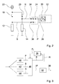
- Figure 2 shows a circuit diagram of the measuring device with the sensor resistor 12 and the reference resistor 14, which are fed by a common power supply device 22 and which can be connected via two switching elements 18, 20 formed as transistors.
- the power supply device 22 feeds the circuit shown in Figure 2 with a constant current of, for example, 1 mA.
- the sensor resistor 12 and the reference resistor 14 are together on a ground.
- the measurand for determining the value of the sensor resistance S is therefore a voltage.
- the reference signal R and the sensor signal S run via a multiplexer 24 in an input 26 of the control and evaluation unit 16, which is connected to an analog-to-digital converter 30.
- the multiplexer 24 has a first input 34 connected to the sensor resistor 12 and has a second input 36 connected to the reference resistor 14. Depending on a control signal of the control and evaluation unit 16, the multiplexer 24 switches in a first mode 42, the sensor signal S to the analog-to-digital converter 30, in a second mode 44, the multiplexer 24 switches the reference signal R to the analog-to-digital converter 30 and in one third mode 46, the multiplexer 24 switches the signals applied to the first input 34 and the second input 36 in a rapid change to the analog-to-digital converter 30 by.
- the control and evaluation unit 16 switches in the first mode 42, the switching element 18 and the switching element 20, in the second mode 44, the switching element 20 and the switching element 18 and the third mode 46 both switching elements 18, 20th one.
- the third operating mode 46 the sensor resistor 12 and the reference resistor 14 are therefore connected in parallel and the inputs 34, 36 of the multiplexer 24 are short-circuited.
- the control and evaluation unit 16 switches back and forth in cycles between the first operating mode 42 and the second operating mode 44 and thus alternately detects the reference signal R via the analog-digital converter 30, which is temporarily stored in a memory 28 (FIG. 3) is, and the sensor signal S. If the sensor signal S is detected, forms the control and evaluation unit 16 from the sensor signal S and the latched reference signal R, the quotient, which forms a fault-corrected measurement, and determines from this depending on a characteristic of the sensor resistor 12 the Internal temperature of the cooking chamber 32.
- the control and evaluation unit 16 starts a plausibility check phase in the third operating mode 46.
- the memory 28 stores the last-detected sensor signal S and the reference signal R last detected before a start of the plausibility check phase. From the latched sensor signal S and the reference signal R, the control and evaluation unit 16 forms a setpoint P 0 for a plausibility signal P, which is present in the third mode 46 at the input 26.
- the control and evaluation unit 16 compares the deviation ⁇ P in a further comparison step 50 with a tolerance stored in the memory 28. If the deviation ⁇ P is greater than the tolerance, then the control and evaluation unit 16 generates a warning signal 38 or an error message, by which the cooking appliance 10 is switched off and deactivated until a customer service arrives.
- control and evaluation unit 16 Further checks the control and evaluation unit 16 in the plausibility phase by the rapid change of the switching position of the multiplexer 24, the correct function of the multiplexer 24, the inputs 34, 36 are short-circuited by the closed switching elements 18, 20, so that in both switching positions of the multiplexer 24th in the case of a correct function of the multiplexer 24 at the output of the same voltage should be applied. Another reason for different output voltages of the multiplexer 24 in the two switching positions could be in contact resistances of the two switching elements 18, 20. If the control and evaluation unit 16 detects a deviation between the two switching positions of the multiplexer 24, then the control and evaluation unit 16 generates an error message.
Landscapes
- Physics & Mathematics (AREA)
- General Physics & Mathematics (AREA)
- Engineering & Computer Science (AREA)
- Chemical & Material Sciences (AREA)
- Combustion & Propulsion (AREA)
- Mechanical Engineering (AREA)
- General Engineering & Computer Science (AREA)
- Electric Ovens (AREA)
- Cookers (AREA)
Applications Claiming Priority (1)
| Application Number | Priority Date | Filing Date | Title |
|---|---|---|---|
| DE200510023448 DE102005023448A1 (de) | 2005-05-20 | 2005-05-20 | Messvorrichtung |
Publications (2)
| Publication Number | Publication Date |
|---|---|
| EP1725075A2 true EP1725075A2 (fr) | 2006-11-22 |
| EP1725075A3 EP1725075A3 (fr) | 2009-01-21 |
Family
ID=36691905
Family Applications (1)
| Application Number | Title | Priority Date | Filing Date |
|---|---|---|---|
| EP06111302A Withdrawn EP1725075A3 (fr) | 2005-05-20 | 2006-03-17 | Dispositif de mesure |
Country Status (2)
| Country | Link |
|---|---|
| EP (1) | EP1725075A3 (fr) |
| DE (1) | DE102005023448A1 (fr) |
Cited By (1)
| Publication number | Priority date | Publication date | Assignee | Title |
|---|---|---|---|---|
| AT503445B1 (de) * | 2006-12-18 | 2007-10-15 | Vaillant Austria Gmbh | Verfahren zur überprüfung eines temperatursensors |
Citations (1)
| Publication number | Priority date | Publication date | Assignee | Title |
|---|---|---|---|---|
| WO2001035065A1 (fr) | 1999-11-10 | 2001-05-17 | Robert Bosch Gmbh | Procede pour controler le bon fonctionnement d'un capteur de temperature de gaz d'echappement et/ou pour regler ce dernier |
Family Cites Families (9)
| Publication number | Priority date | Publication date | Assignee | Title |
|---|---|---|---|---|
| JPS63191935A (ja) * | 1987-02-04 | 1988-08-09 | Matsushita Seiko Co Ltd | 温度センサ− |
| DE4032949C2 (de) * | 1990-10-17 | 1998-04-30 | Miele & Cie | Backofen |
| US6091324A (en) * | 1998-11-13 | 2000-07-18 | Ford Motor Company | Comparing sensor outputs to distinguish between sensor faults and extreme temperature conditions |
| DE19955972C2 (de) * | 1999-11-19 | 2002-03-14 | Heraeus Electro Nite Int | Verfahren zum Kalibrieren eines Temperatursensors |
| US6612737B1 (en) * | 1999-12-29 | 2003-09-02 | Affymetrix, Inc. | System and method for self-calibrating measurement |
| DE10112139A1 (de) * | 2001-03-14 | 2002-09-19 | Bosch Gmbh Robert | Verfahren und Vorrichtung zur Überwachung eines Sensors |
| JP2004157024A (ja) * | 2002-11-07 | 2004-06-03 | Omron Corp | 温度検出装置 |
| TW567054B (en) * | 2002-11-28 | 2003-12-21 | Actherm Inc | Method for assembling electric clinical thermometer and structure thereof |
| DE10329039B3 (de) * | 2003-06-27 | 2005-01-05 | Audi Ag | Verfahren zur Überprüfung der Funktionsfähigkeit eines Temperatursensors |
-
2005
- 2005-05-20 DE DE200510023448 patent/DE102005023448A1/de not_active Withdrawn
-
2006
- 2006-03-17 EP EP06111302A patent/EP1725075A3/fr not_active Withdrawn
Patent Citations (1)
| Publication number | Priority date | Publication date | Assignee | Title |
|---|---|---|---|---|
| WO2001035065A1 (fr) | 1999-11-10 | 2001-05-17 | Robert Bosch Gmbh | Procede pour controler le bon fonctionnement d'un capteur de temperature de gaz d'echappement et/ou pour regler ce dernier |
Cited By (1)
| Publication number | Priority date | Publication date | Assignee | Title |
|---|---|---|---|---|
| AT503445B1 (de) * | 2006-12-18 | 2007-10-15 | Vaillant Austria Gmbh | Verfahren zur überprüfung eines temperatursensors |
Also Published As
| Publication number | Publication date |
|---|---|
| EP1725075A3 (fr) | 2009-01-21 |
| DE102005023448A1 (de) | 2006-11-23 |
Similar Documents
| Publication | Publication Date | Title |
|---|---|---|
| DE19640937B4 (de) | Vorrichtung zur Überwachung der Meßwerterfassung bei einer Motorsteuerung | |
| DE69222587T2 (de) | Fehlererfassungseinrichtung für Treiberschaltung | |
| DE102004014728B4 (de) | Einheit zum Erfassen einer physikalischen Größe | |
| DE102010000663A1 (de) | Vorrichtung und Verfahren zur Steuerung und Auswertung eines Abgassensors | |
| EP2506436B1 (fr) | Circuit d'entrée pour un composant d'entrée et procédé de fonctionnement d'un circuit d'entrée | |
| WO2014009207A1 (fr) | Dispositif de diagnostic d'une circuiterie | |
| WO2009013273A1 (fr) | Procédé d'analyse d'erreurs pour une sonde lambda | |
| EP3649476B1 (fr) | Dispositif et procédé permettant de vérifier une aptitude à fonctionner d'une résistance d'un système de batterie | |
| DE3919005A1 (de) | Temperaturerfassungsschaltung und ueberwachungsverfahren an einer brotbackmaschine | |
| EP0581993B1 (fr) | Circuit de commande d'une charge et de détection de rupture d'un conducteur | |
| DE3941995A1 (de) | Verfahren und vorrichtung zur ueberwachung der funktionsfaehigkeit einer sonden-heizeinrichtung | |
| DE102005037717B3 (de) | Verfahren und Vorrichtung zur Diagnose eines Außentemperatursensors | |
| DE4229833C2 (de) | Druckinformation-Verarbeitungseinrichtung zur Verwendung in einer Vakuumeinheit | |
| DE102014219130B4 (de) | Diagnoseschaltung und Verfahren zum Betreiben einer Diagnoseschaltung | |
| EP0203350B1 (fr) | Dispositif de mesure de la température pour mesurer de grands changements en température | |
| DE102011075679A1 (de) | Sensoranordnung | |
| EP1818536A2 (fr) | Procédé et dispositif de surveillance d'au moins une bougie de préchauffage d'un véhicule automobile | |
| EP1352255B1 (fr) | Dispositif de determination de la resistance interieure d'une sonde a oxygene lineaire (sonde lambda) | |
| DE102008007397A1 (de) | Verfahren zur Überwachung von wenigstens einer Glühstiftkerze eines Brennkraftmotors und Vorrichtung hierzu | |
| EP1725075A2 (fr) | Dispositif de mesure | |
| EP2622417A2 (fr) | Procédé de récupération destiné à un appareil comportant une sortie de courant analogique pour l'émission d'une valeur de mesure ou d'une valeur de réglage | |
| DE19855870B4 (de) | Flußsensor der wärmeempfindlichen Art | |
| DE19923688A1 (de) | Verfahren und Vorrichtung zur Fehlererkennung bei Meßgrößen in einem Fahrzeug | |
| DE2229324A1 (de) | Anlage zum ueberwachen des drehmoments eines motors | |
| WO2021058302A1 (fr) | Procédé et dispositif pour déterminer un élément d'information de température décrivant la température d'un détecteur de température de résistance, onduleur, véhicule et programme informatique |
Legal Events
| Date | Code | Title | Description |
|---|---|---|---|
| PUAI | Public reference made under article 153(3) epc to a published international application that has entered the european phase |
Free format text: ORIGINAL CODE: 0009012 |
|
| AK | Designated contracting states |
Kind code of ref document: A2 Designated state(s): AT BE BG CH CY CZ DE DK EE ES FI FR GB GR HU IE IS IT LI LT LU LV MC NL PL PT RO SE SI SK TR |
|
| AX | Request for extension of the european patent |
Extension state: AL BA HR MK YU |
|
| PUAL | Search report despatched |
Free format text: ORIGINAL CODE: 0009013 |
|
| AK | Designated contracting states |
Kind code of ref document: A3 Designated state(s): AT BE BG CH CY CZ DE DK EE ES FI FR GB GR HU IE IS IT LI LT LU LV MC NL PL PT RO SE SI SK TR |
|
| AX | Request for extension of the european patent |
Extension state: AL BA HR MK YU |
|
| 17P | Request for examination filed |
Effective date: 20090721 |
|
| 17Q | First examination report despatched |
Effective date: 20090814 |
|
| AKX | Designation fees paid |
Designated state(s): AT BE BG CH CY CZ DE DK EE ES FI FR GB GR HU IE IS IT LI LT LU LV MC NL PL PT RO SE SI SK TR |
|
| RAP1 | Party data changed (applicant data changed or rights of an application transferred) |
Owner name: BSH HAUSGERAETE GMBH |
|
| STAA | Information on the status of an ep patent application or granted ep patent |
Free format text: STATUS: THE APPLICATION IS DEEMED TO BE WITHDRAWN |
|
| 18D | Application deemed to be withdrawn |
Effective date: 20160322 |