EP1726535A1 - Emballage avec ligne d'affaiblissement et méthode et appareil pour sa production - Google Patents
Emballage avec ligne d'affaiblissement et méthode et appareil pour sa production Download PDFInfo
- Publication number
- EP1726535A1 EP1726535A1 EP06010805A EP06010805A EP1726535A1 EP 1726535 A1 EP1726535 A1 EP 1726535A1 EP 06010805 A EP06010805 A EP 06010805A EP 06010805 A EP06010805 A EP 06010805A EP 1726535 A1 EP1726535 A1 EP 1726535A1
- Authority
- EP
- European Patent Office
- Prior art keywords
- thread
- tear
- web
- region
- weakening line
- Prior art date
- Legal status (The legal status is an assumption and is not a legal conclusion. Google has not performed a legal analysis and makes no representation as to the accuracy of the status listed.)
- Withdrawn
Links
- 238000004519 manufacturing process Methods 0.000 title claims abstract description 9
- 230000003313 weakening effect Effects 0.000 title claims description 36
- 238000000034 method Methods 0.000 title claims description 8
- 235000019504 cigarettes Nutrition 0.000 claims abstract description 21
- 238000004806 packaging method and process Methods 0.000 claims abstract description 11
- 239000005022 packaging material Substances 0.000 claims description 17
- 238000005520 cutting process Methods 0.000 claims description 16
- 238000012546 transfer Methods 0.000 claims description 5
- 230000007704 transition Effects 0.000 claims description 3
- 239000000463 material Substances 0.000 abstract description 8
- 238000012856 packing Methods 0.000 description 7
- 238000013461 design Methods 0.000 description 4
- 238000004026 adhesive bonding Methods 0.000 description 3
- 230000015572 biosynthetic process Effects 0.000 description 3
- 210000000056 organ Anatomy 0.000 description 3
- 238000007789 sealing Methods 0.000 description 3
- 239000000853 adhesive Substances 0.000 description 2
- 230000001070 adhesive effect Effects 0.000 description 2
- 230000005540 biological transmission Effects 0.000 description 2
- 230000006835 compression Effects 0.000 description 2
- 238000007906 compression Methods 0.000 description 2
- 239000011888 foil Substances 0.000 description 2
- 239000000123 paper Substances 0.000 description 2
- 229920006300 shrink film Polymers 0.000 description 2
- 229920000298 Cellophane Polymers 0.000 description 1
- 230000009977 dual effect Effects 0.000 description 1
- 230000002093 peripheral effect Effects 0.000 description 1
- 229920003023 plastic Polymers 0.000 description 1
- 239000002985 plastic film Substances 0.000 description 1
- 238000003825 pressing Methods 0.000 description 1
- 238000012545 processing Methods 0.000 description 1
- 238000005096 rolling process Methods 0.000 description 1
- 238000000926 separation method Methods 0.000 description 1
Images





Classifications
-
- B—PERFORMING OPERATIONS; TRANSPORTING
- B65—CONVEYING; PACKING; STORING; HANDLING THIN OR FILAMENTARY MATERIAL
- B65D—CONTAINERS FOR STORAGE OR TRANSPORT OF ARTICLES OR MATERIALS, e.g. BAGS, BARRELS, BOTTLES, BOXES, CANS, CARTONS, CRATES, DRUMS, JARS, TANKS, HOPPERS, FORWARDING CONTAINERS; ACCESSORIES, CLOSURES, OR FITTINGS THEREFOR; PACKAGING ELEMENTS; PACKAGES
- B65D75/00—Packages comprising articles or materials partially or wholly enclosed in strips, sheets, blanks, tubes or webs of flexible sheet material, e.g. in folded wrappers
- B65D75/52—Details
- B65D75/58—Opening or contents-removing devices added or incorporated during package manufacture
- B65D75/5827—Tear-lines provided in a wall portion
-
- B—PERFORMING OPERATIONS; TRANSPORTING
- B65—CONVEYING; PACKING; STORING; HANDLING THIN OR FILAMENTARY MATERIAL
- B65B—MACHINES, APPARATUS OR DEVICES FOR, OR METHODS OF, PACKAGING ARTICLES OR MATERIALS; UNPACKING
- B65B61/00—Auxiliary devices, not otherwise provided for, for operating on sheets, blanks, webs, binding material, containers or packages
- B65B61/18—Auxiliary devices, not otherwise provided for, for operating on sheets, blanks, webs, binding material, containers or packages for making package-opening or unpacking elements
- B65B61/182—Auxiliary devices, not otherwise provided for, for operating on sheets, blanks, webs, binding material, containers or packages for making package-opening or unpacking elements by applying tear-strips or tear-tapes
-
- B—PERFORMING OPERATIONS; TRANSPORTING
- B65—CONVEYING; PACKING; STORING; HANDLING THIN OR FILAMENTARY MATERIAL
- B65D—CONTAINERS FOR STORAGE OR TRANSPORT OF ARTICLES OR MATERIALS, e.g. BAGS, BARRELS, BOTTLES, BOXES, CANS, CARTONS, CRATES, DRUMS, JARS, TANKS, HOPPERS, FORWARDING CONTAINERS; ACCESSORIES, CLOSURES, OR FITTINGS THEREFOR; PACKAGING ELEMENTS; PACKAGES
- B65D75/00—Packages comprising articles or materials partially or wholly enclosed in strips, sheets, blanks, tubes or webs of flexible sheet material, e.g. in folded wrappers
- B65D75/52—Details
- B65D75/58—Opening or contents-removing devices added or incorporated during package manufacture
- B65D75/66—Inserted or applied tearing-strings or like flexible elements
- B65D75/68—Inserted or applied tearing-strings or like flexible elements extending through wrapper closure or between wrapper layers
Definitions
- the invention relates to a cuboid pack, in particular cigarette pack, with outer wrapping made of foil and with a attached to the outer sheath, finite tear thread or a line of weakness. Furthermore, the invention relates to a method and an apparatus for producing packaging material formed in the above manner.
- Packages of different shape and design are often provided to protect the contents of the package with an outer wrapper made of film or a similar packaging material.
- an outer wrapper made of film or a similar packaging material.
- this is often provided with a tear thread or tear strip, which is attached by gluing or sealing to the outer sheath. This can be severed by detecting the tear thread at a handle end and so eliminated.
- the invention relates to such packages, in particular with cigarette packs in the execution as cuboid hard pack (made of thin cardboard).
- the invention is based on the object, a tear thread or the weakening line or tear strip on the outer sheath of a pack to be mounted so that upon actuation of the tear thread or the weakening line, the outer sheath is reliably removed in its entirety.
- the package according to the invention is characterized in that the tear thread or the weakening line in the region of a large front wall and / or rear wall obliquely or approximately diagonally extends from a (lower) Packungsecke to a diagonally opposite (upper) Packungsecke.
- the (approximately) diagonal course of the tear thread or the weakening line in the area of at least one of the large-area packing walls ensures that the outer wrapper is optimally severed the first time so that the remaining wrapper parts can be pulled off in a simple manner via packing corners.
- the invention is particularly suitable for cigarette packs of the type folding box with shrink film as outer sheath.
- a special feature is the weakening line of the outside envelope formed as a foil or the like. This forms a weakening of the wall thickness of the packaging material while maintaining the tightness. In the area of the linear material weakening, the film can be easily cut through. Alternatively, this may be a double line, that is, two parallel lines of weakness defining a detachable strip of material of the film, or a single line of weakness that can be severed by hand upon opening the enclosure.
- the tear thread or the weakening line is arranged so that in the region of narrow, upright side surfaces, a transversely directed, rectilinear portion is formed, adjacent to an end wall on the one hand and to a bottom wall on the other hand, and that these sections respectively rectified diagonal portions of the front wall and Connect rear wall together.
- a special feature is the production of a (film) web with continuous tear thread or tear strip or continuous weakening line as well as blanks for outer sheaths.
- the tear thread or tear strip or line of weakness during continuous transport of the web of film, paper or the like is applied thereto, wherein the tear thread is moved by an exactly controlled thread guide according to the thread configuration to be produced transversely to the conveying direction of the (film) web ,
- thread sections ie finished tear strip or tear strip with respect to the shape and length applied to the continuous (film) web.
- the tear strips are separated by a contoured cut of a thread path and thereby placed directly on the track according to the position of a blank for the outer sheath.
- the inventive device for applying a continuous tear thread or tear strip on a continuously moving web has a special guide member for the tear thread, namely with a guide roller.
- This has a double function, namely serves for applying the tear thread to the web and at the same time as a management body.
- the guide roller is moved by a controlled gear in the direction transverse to the web or transverse to the conveying direction thereof, so that the tear thread is transmitted in a curved configuration on the web.
- the drive of the tearing thread drawn from a thread bobbin is controlled taking into account the relative movement between the preferably continuously and at a uniform speed promoted web on the one hand and the tear thread on the other hand.
- the device according to the invention for applying contoured thread sections or finished tear thread has a contoured, namely curved separating knife, which at each working cycle during instantaneous standstill of the web or a web section separates a tear thread formed according to the invention from a yarn path fed in the transverse direction and positionally accurate applies to the (film) web, in the region of a blank to be separated from this.
- Both methods or devices are expediently set up for double-lane operation.
- cigarette packs are shown as preferred applications, namely a hinged-lid pack 10 and a pack of packs for cigarette packs, namely a cigarette rod 11 ( Figure 11).
- the aforementioned packages are hard packs of (thin) cardboard and each surrounded by an outer sheath. This consists of a thin, transparent plastic film, in particular shrink films, made of cellophane, but can also consist of other packaging material, for example made of paper.
- a blank 12, 13 for forming the outer sheath consists of front wall 14, rear wall 15 and side walls 16, 17. Furthermore, the blanks 12, 13 form end walls 18 and a bottom wall 19 (hinged box 10).
- the side wall 16 is positioned as a closed strip of material between the front wall 14 and rear wall 15, while the opposite side wall 17 consists of an outer side flap 20 and an inner side flap 21.
- the two side flaps 20, 21 cover each other and are by sealing or gluing together connected.
- End wall 18 and bottom wall 19 consist of over the full length of the blank 12, 13 continuous end tabs 22, 23rd
- the thus formed blank 12, 13 is folded in a known manner in a first folding step in a U-shape around the package, namely folding box 10 or cigarette rod 11.
- the side tabs 20, 21, which initially protrude beyond the package, are folded one after the other with partial overlapping (FIGS. 1, 11).
- the end flaps 22, 23 are folded to form the end walls 18 and the bottom wall 19, respectively.
- a tear thread 24 is attached to the pack or to its outer wrapper according to FIGS. 1 to 17.
- the possibly strip-shaped tear-open thread 24 is preferably connected by gluing or sealing to the inside of the blank 12, 13.
- grip tab 25 is formed, which extends in the finished package on the edge of the side wall 17 and the side flap 20 and so can be detected by hand. With the aid of this grip tab 25, the tear-open thread 24 can be pulled off while severing the outer sheath or the blank 12, 13.
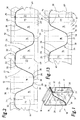
- the tear thread 24 is attached to the blank 12, 13 in a particular configuration such that the outer wrap is severed by the severed tear thread 24 substantially diagonally in the area of the large-area package sides. As a result, formed corner caps of the outer sheath can be easily removed "over corner”.
- the (one-piece) tear-open thread 24 is positioned on the blank 12, 13 such that in the region of the front wall 14 on the one hand and the rear wall 15 on the other hand an approximately diagonal course is given (in a common imaginary diagonal plane).
- Thread sections 26, 27 thus extend approximately from a lower packing corner 28 to the diagonally opposite packing corner 29.
- the thread section 26, 27 extends at a short distance from the respective packing corner 28, 29 and thus from the bottom 19 on the one hand and the end wall 18 on the other hand.
- the tear thread forms a rounding 30 as a transition into transversely directed, straight thread sections 31, 32.
- a continuous thread section 31 extends in the region of the one-piece side wall 16, across them and directly adjacent or above the bottom wall 19.
- the other thread section 32 extends in the upper region - adjacent to the end wall 18 and below the same - in the region of the side wall 17.
- This thread section 32 consists of two mutually partially overlapping sections. The tear thread is therefore arranged so that cover the ends of the same. In the area of the outer side flap 20, a grip tab 25 is attached to the portion of the thread section 32.
- a special feature is the production of the blanks 12, 13 from a continuous web 33, from the blanks 12, 13 in a cutting unit 34 of the packaging machine (Fig. 3) are separated along a separating cut 68.
- the tear thread 24 is applied to the continuous web 33, preferably in continuous, continuous conveying movement.
- the likewise continuously supplied tear thread 24 is guided and applied to the web 33 that an approximately meandering or wave-shaped configuration of the tear thread 24 is given (Fig. 2).
- the thereby formed, extending in the longitudinal direction of the web 33 thread sections 31, 32 are unequal length.
- the end wall 18 facing the thread section 32 has a greater length than the thread section 31 in the region of the side wall 16 because of the adjacent side tabs 20, 21.
- the application of the tear thread 24 to the continuous web 33 includes a procedural and technical feature.
- the tear thread 24 is transferred by a guide member to the web 33, in the present case by a rotating guide roller 35, this is attached to a holder.
- the tear thread 24 is fed so that a sufficient thread portion rests on the circumference of the guide roller 35.
- This is movable transversely to the continuously conveyed web 33 by means of a special, controlled transmission, such that the tear thread 24 is applied to the web 33 with one shown in FIG. 2 or in FIG. 12 or in a similar course.
- a device for applying the tear thread 24 to the web 33 is expediently part of the packaging machine (FIG. 3).
- the unit is marked as section IV. Thereafter, the withdrawn from reels 38 web 33 of a thread unit 39 is supplied. This is shown by way of example in FIG. 4.
- the tear thread 24 is withdrawn from a thread bobbin 40.
- the tear thread 24 is expediently one-sided, namely on the web 33 facing side, provided with an adhesive.
- the thread bobbin 40 is rotationally driven, in this example, at a constant conveying speed of the withdrawn tearing thread 24.
- the tear thread is guided over compensating rollers 41 which are movable relative to each other and cause a compensation of the Aufr effetstMails 24 when starting or stopping the packaging machine, ie in operating situations that deviate from the standard operating mode.
- the actual thread aggregate consists of two gear units 42, 43.
- the gear unit 42 serves to compensate for the conveying speed of the tearing thread 24 due to the relative movement between the web 33 and tear thread 24.
- the gear unit 43 performs the controlled transverse movements of the transfer member, so the guide roller 35, for the tear thread 24 through.
- the gear unit 42 must cause an increased conveying speed of the tearing thread 24 during formation of the thread section 26 and 27.
- the conveying speed of the tearing thread 24 is substantially the same as that of the web 33 coincide.
- the gear unit 42 forms an alternating supply of thread length, which is reduced at increased conveying speed and rebuilt at the lower conveying speed.
- This thread supply consists of a thread loop as a result of deflection about a movable dancer roller 44.
- This is slidably mounted on a support 45, namely in a slot guide 46.
- two other, fixed guide rollers 47, 48 are mounted for the tear thread.
- the dancer roll 44 is centered between the pulleys 47, 48, however offset to these, stored, so that when moving the dancer roller 44, the distance from the pulleys 47, 48 is larger or smaller.
- the dancer roll 44 is controlled in exact accordance with the trajectory of the web 33 and the tear thread 24.
- the dancer roller 44 is assigned a drive motor 49 as a drive member. This is connected via a gearbox, via a crank gear 50 with the dancer roller 44.
- Fig. 9 shows the side facing away from Fig. 4 side of the carrier 45 with the crank gear 50, wherein a connecting rod 51 is connected to the dancer roller 44.
- the servomotor 49 acts on a crank 52.
- the gear unit 43 controls the movements of the guide roller 35, in a double sense: First, it is about the required movements of the guide roller 35 transverse to the web 33 and the other is about the correct angular position of the guide roller 35, so that they on the Angular position of the tear thread 24 is aligned with the web 33.
- the guide roller 35 is mounted for transverse movement on a transversely movable carrier, namely on a guide carriage 53. This is displaceable on a transverse guide 54.
- the drive is via a pull rod 55, which may be driven by a servo motor or is controlled by a support roller of a curve.
- the guide roller 35 is fastened with a support piece 56 to the guide carriage 53, namely with a fork-shaped, pivotable holder 57 mounted on the support piece 56.
- the holder 57 is rotatable with the guide roller 35 about an axis or pivotable, namely transversely to the axis of the guide roller 35.
- a pivoting gear is mounted below the support piece 56, which consists of a steering rod 58 which is connected via a hinge 59 with a pivot arm 60 of the holder 57.
- the control of the steering rod 58 is not shown here and is analogous to the control of the pull rod 55, such that the guide roller 35 is always aligned in the feed direction of the tear thread 24 is.
- Fig. 6 shows a position of the guide roller 35 during the formation of the slanted yarn section 26, 27th
- the guide roller 35 is formed so that it can fulfill a dual function, namely the one hand guide the tearing thread 24 and on the other hand pressing the same to the web 33.
- the guide roller 35 has namely lateral elevations, in the area of the system of the tearing thread 24 to the railway 33 are not effective.
- the guide roller 35 consists of three individual rollers 61, 62, 63.
- the average single roller 62 receives the tear thread 24 on the circumference, while the lateral single rollers 61, 63 take over the function of flanged wheels.
- the individual rollers 61, 62, 63 are independently rotatable and mounted on a fixed support shaft 64 by means of rolling bearings.
- the support shaft 64 consists of staggered sections, similar to a crank axle.
- the individual rollers 61, 62, 63 are arranged so that the central single roller 62 rotates centrally to an imaginary axis, while the single side rollers 61, 63 offset rotate, with the result that in the region of the transfer of the tearing thread 24 to the web 33 the Single rollers 61, 62, 63 are always aligned with their peripheral surfaces in a circumferential plane (Fig. 8).
- a support roller 36 is mounted below the guide roller, namely below the support piece 56, which causes a slight deflection and guidance of the tearing thread 24 to the guide roller 35.
- the conveying movement of the tearing thread 24 in the region of the transfer to the web 33 results from the conveying speed of the web 33. This pulls the tearing thread 24 through the adhesive connection.
- the transfer of the tear thread 24 to the web 33 takes place in the region of a guide roller 65 of the web 33. At this is the guide roller 35 at.
- the guide roller 65 is mounted elastically, namely on a pivot arm 66, which is loaded by a compression spring 67 in the direction of the guide roller 35.
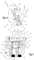
- FIG. 10 shows an alternative to the thread unit 39 according to FIG. 4.
- the gear unit 43 corresponds to the embodiment of FIG. 4.
- the dancer roll 44 with servo drive is replaced by a compensating member, which rotates exclusively.
- This rotating sheave 37, at the periphery of the tear thread 24 is applied, caused by the eccentric shape with each revolution, a length compensation corresponding to the differentiated conveying speeds of the tear thread 24th
- the packaging machine and its units are set up in the present example to double-track operation.
- the (double-width) web 33 consists of two blank sheets.
- the thread unit 39 is adapted to the simultaneous attachment of two tear threads 24.
- two thread bobbins 40 of the same equipment are provided, namely arranged one above the other.
- the other organs of the thread unit 39 and the gear units 42 and 43 are set either by an appropriate design or by double arrangement on the processing of the two tear threads 24.
- two guide rollers 35 are provided which are operated or adjusted simultaneously by common organs.
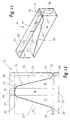
- the cigarette rod 11 according to FIG. 11 is manufactured analogously to the folding box 10 with regard to the outer envelope.
- the blank 12 (FIG. 12) is formed such that the skew-oriented thread sections 26, 27 have proportionally a greater length in relation to the thread sections 31, 32.
- the outer sheaths are structurally coincident.
- the tear thread 24 or tear strip can also be produced in sections and fed to a single blank 12 or the web 33 of film or the like (FIGS. 13 to 17). In each case, complete tear thread 24 are manufactured and applied to the web 33.
- the individual tear thread 24 have the same contour as in the embodiment of FIG. 1, Fig. 2. However, the tear thread extends with a piece of the thread portion 32 into the grip tab 25. Another end of the thread section 32 lies at a distance from the grip tab 25 of the adjacent blank 12, so that the tear thread 24 is mounted offset on the blank 12 as a whole.
- tear thread 24 is completely made in the present contour, other designs are possible, in particular without rounding 30, so for example in zig-zag design or with other corners.
- the thread unit 39 for producing and attaching tear-open thread 24 works with (at least) a severing knife, namely a thread knife 69, 70 for severing a contoured tear thread 24 from the front end of a material web, namely a thread path 71, 72.
- 70 has a shape which corresponds to that of the tear-open thread 24 to be separated, in the present case thus approximately V- or meander-shaped.
- the thread path 71, 72 is fed transversely to the web 33 to a cutting block 73 of the thread unit 39.
- the thread knife 69, 70 movable up and down.
- a front end of the suture path 71, 72 is held within the cutting block 73 as a projection, corresponding to the width of the tear-open 24.
- the suture path 71, 72 runs within the cutting block 73 in a slot-like guide 74 and between an upper and lower guide roller 75, 76th
- the thread knife 69, 70 is moved upwards from a lower starting position (FIG.
- Above the thread path 71, 72 a fixed counter knife 77 is formed, which has the same contour as the thread knife 69, 70.
- the thread knife 69, 70 leads the severed tear thread 24 on continued (upward) movement directly to the web 33 and puts the tear thread 24 on the underside of the web 33 (Fig. 16).
- the thread knife 69, 70 is designed for this purpose as a (shaped, contoured) carrier or beam 85, which is in an upright also contoured recess 78 of the cutting block 73 movable up and down.
- the beam 85 is provided with suction holes 79 at the top adjacent to the thread knives 69, 70.
- the suction holes 79 are connected at least during the transport phase of the tearing thread 24 to a vacuum source.
- the web 33 is conveyed through the cutting block 73 in an (upper) guide slot 80.
- an (elastic) pressure piece 81 in the cutting block 73 is formed as an abutment when the tearing thread 24 is pressed.
- the pressure piece 81 can be heated to seal the tearing thread 24.
- the web 33 is also continuously conveyed in this embodiment.
- a web section 82 in the area of the thread unit 39 or of the cutting block 73 is controlled such that there is a temporary standstill, namely during the attachment of the tear thread 24.
- the web 33 is for this purpose via two pivotally mounted and synchronously reciprocable Balancing pendulum 83, 84 out. This mechanism, which is known per se, causes a momentary standstill of the web section 82 despite a substantially continuous drive.
- contoured beams 85 as a carrier of the thread knives 69, 70 are each attached to a (horizontal) support arm 86 with their ends. This is mounted in a machine frame and up in a slot 87 movable up and down to allow the separation process for the tear thread 24 and the supply to the web 33.
- the device shown in FIGS. 14 to 17 is also set up for two-lane operation. Accordingly, a correspondingly formed cutting block 73 is fed with two yarn paths 71, 72, in one arrangement one above the other.
- the upper suture path 71 is passed directly into the cutting block 73, while the lower suture path 72 initially passes below the cutting block 73 and is then directed over guide rollers 88 upwards and then into a horizontal plane.
- the web 33 is double-width, so that in the transverse direction in each case two blanks 12 are adjacent.
- FIGS. 18 to 20 A particular alternative to the described embodiments with tear strips is shown in FIGS. 18 to 20.
- the packaging material itself ie in particular the film for the outer envelope of the (cigarette) pack is with one or more continuous or continuous line of weakness 89, 90 and 91, respectively.
- These are a linear weakening of the wall thickness of the packaging material, but while maintaining a (inside) continuous closed, dense film.
- the cross-sectional weakening or the weakening line 89, 90, 91 created in this way enables easy, manual severing of the film in this area.
- the lines of weakness 89, 90, 91 are applied by laser.
- a laser beam can be controlled so precisely that a linear material weakening is possible even with very thin-walled films.
- the course of the single or multiple weakening line 89, 90, 91 corresponds to the course of the tear thread 24 in the preceding embodiments, wherein the sections of the tear thread denoted with line section line sections of the weakening line 89, 90, 91.
- two parallel lines of weakness 89, 90 are provided, namely continuous lines.
- the two lines of weakness 89, 90 run parallel to each other at a small distance, so that a strip of material 92 is formed between the two lines of weakness. This can be cut out like a tear strip by hand from the walls of the outer sheath or the blank 12.
- a grip tab 25 is provided which facilitates the tearing process.
- the shape or the course of the weakening lines 89, 90 corresponds to the described embodiments.
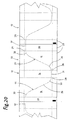
- Fig. 20 shows a particular embodiment with a single line of weakness 91, preferably also made by laser. This weakening line is severed by (manual) pulling apart adjacent regions of the film or the blank 12, that is, without a tear tab.
- a laser is arranged above the longitudinally preferably continuously conveyed web 33 which is transversely movable in a controlled manner and in coordination with the conveying movement of the web 33 relative to the web 33, such that the desired formation of the lines of weakness 89, 90, 91 is generated.
- the device for moving a laser head can be designed analogously to FIG. 5 or FIG. 7.
Landscapes
- Engineering & Computer Science (AREA)
- Mechanical Engineering (AREA)
- Auxiliary Devices For And Details Of Packaging Control (AREA)
Applications Claiming Priority (1)
| Application Number | Priority Date | Filing Date | Title |
|---|---|---|---|
| US11/137,496 US7588143B2 (en) | 2001-09-14 | 2005-05-26 | Pack with tear-open thread, and process and apparatus for producing the same |
Publications (1)
| Publication Number | Publication Date |
|---|---|
| EP1726535A1 true EP1726535A1 (fr) | 2006-11-29 |
Family
ID=36782557
Family Applications (1)
| Application Number | Title | Priority Date | Filing Date |
|---|---|---|---|
| EP06010805A Withdrawn EP1726535A1 (fr) | 2005-05-26 | 2006-05-26 | Emballage avec ligne d'affaiblissement et méthode et appareil pour sa production |
Country Status (2)
| Country | Link |
|---|---|
| US (1) | US7588143B2 (fr) |
| EP (1) | EP1726535A1 (fr) |
Cited By (2)
| Publication number | Priority date | Publication date | Assignee | Title |
|---|---|---|---|---|
| NL2004489C2 (nl) * | 2010-03-31 | 2011-10-04 | Johnson Yacoub | Verpakkingsmateriaal en werkwijze voor het vervaardigen ervan en product voorzien van het verpakkingsmateriaal. |
| WO2012175507A1 (fr) * | 2011-06-20 | 2012-12-27 | Philip Morris Products S.A. | Paquet emballé doté d'un emballage extérieur pourvu d'une ligne d'affaiblissement |
Families Citing this family (10)
| Publication number | Priority date | Publication date | Assignee | Title |
|---|---|---|---|---|
| US7588143B2 (en) | 2001-09-14 | 2009-09-15 | Focke & Co. (Gmbh & Co. Kg) | Pack with tear-open thread, and process and apparatus for producing the same |
| US8702670B2 (en) * | 2004-06-30 | 2014-04-22 | Mcneil-Ppc, Inc. | Intravaginal device with controlled expansion |
| US8266868B2 (en) * | 2007-06-01 | 2012-09-18 | Phillip Morris Usa Inc. | Opening device for outer wrapping and method for forming |
| US20140262903A1 (en) * | 2013-03-15 | 2014-09-18 | Altria Client Services Inc. | Label having tear strip |
| WO2015009794A2 (fr) * | 2013-07-17 | 2015-01-22 | Magna Mirrors Of America, Inc. | Système de fabrication de film enroulé |
| CN203416809U (zh) * | 2013-07-31 | 2014-02-05 | 刘秋明 | 电子烟盒 |
| US20160227835A1 (en) * | 2015-02-06 | 2016-08-11 | R.J. Reynolds Tobacco Company | Container with tamper evident portion |
| US10239677B2 (en) | 2015-07-29 | 2019-03-26 | Sonoco Development, Inc. | Easy-open media wrapper |
| US11462132B2 (en) | 2019-01-03 | 2022-10-04 | Altria Client Services Llc | Label for pack |
| EP3825244B1 (fr) | 2019-11-22 | 2026-01-21 | S.C. Johnson & Son, Inc. | Découpe de carton pour un carton d'expédition exposable |
Citations (10)
| Publication number | Priority date | Publication date | Assignee | Title |
|---|---|---|---|---|
| FR2127136A5 (fr) | 1971-02-25 | 1972-10-13 | Godard & Fils Ets | |
| DE8802205U1 (de) * | 1988-02-20 | 1988-04-07 | Baudisch, Wolfgang, Dipl.-Ing., 8042 Oberschleißheim | Einwegschutzpackung |
| EP0343857A2 (fr) | 1988-05-25 | 1989-11-29 | Philip Morris Products Inc. | Enveloppe pour récipient, méthode et dispositif pour sa fabrication |
| EP0395249A1 (fr) | 1989-04-24 | 1990-10-31 | Philip Morris Products Inc. | Enveloppe d'emballage avec bande à déchirer intégrée et procédé et dispositif pour faire celle-ci |
| EP0601583A1 (fr) * | 1992-12-09 | 1994-06-15 | Fabriques De Tabac Reunies S.A. | Procédé et dispositif pour la fabrication d'emballages avec un ruban d'arrachement disposé hélicoidalement |
| DE29700830U1 (de) * | 1996-11-25 | 1997-03-13 | Ostma Maschinenbau GmbH, 53909 Zülpich | Umverpackung für eine Verpackungseinheit aus mehreren gleichen Primärverpackungen |
| DE29715546U1 (de) | 1997-08-29 | 1999-01-07 | Gustav Stabernack GmbH, 36341 Lauterbach | Displayverpackungsbehälter |
| DE10041020A1 (de) | 2000-08-22 | 2002-03-07 | Topack Verpacktech Gmbh | Einrichtung und Verfahren zur Erzeugung wenigstens einer Schwächungslinie an einem flächigen Verpackungsmaterial und Verpackungsmaterial |
| WO2003024834A1 (fr) | 2001-09-14 | 2003-03-27 | Focke & Co. (Gmbh & Co.) | Emballage pourvu d'un fil de rupture, procede et dispositif de fabrication associes |
| US20050269220A1 (en) * | 2001-09-14 | 2005-12-08 | Focke & Co. (Gmbh & Co. Kg) | Pack with tear-open thread, and process and apparatus for producing the same |
Family Cites Families (8)
| Publication number | Priority date | Publication date | Assignee | Title |
|---|---|---|---|---|
| US2342646A (en) * | 1941-03-18 | 1944-02-29 | Crommey George | Cigarette package |
| JPS5638075U (fr) | 1979-08-28 | 1981-04-10 | ||
| JPS5688668U (fr) | 1979-12-07 | 1981-07-15 | ||
| JPS5942377Y2 (ja) | 1981-09-30 | 1984-12-11 | 勝之 辻村 | 煙草の紙箱の包装構造 |
| JPH0228419U (fr) | 1988-08-15 | 1990-02-23 | ||
| JPH0435561U (fr) | 1990-07-23 | 1992-03-25 | ||
| JPH04253655A (ja) | 1990-12-29 | 1992-09-09 | Yasuo Sato | 小物収容ケース等の包装用フィルム |
| JPH08164926A (ja) | 1994-12-09 | 1996-06-25 | Sony Corp | フィルム包装装置、包装用フィルム、およびその製造方法 |
-
2005
- 2005-05-26 US US11/137,496 patent/US7588143B2/en not_active Expired - Fee Related
-
2006
- 2006-05-26 EP EP06010805A patent/EP1726535A1/fr not_active Withdrawn
Patent Citations (10)
| Publication number | Priority date | Publication date | Assignee | Title |
|---|---|---|---|---|
| FR2127136A5 (fr) | 1971-02-25 | 1972-10-13 | Godard & Fils Ets | |
| DE8802205U1 (de) * | 1988-02-20 | 1988-04-07 | Baudisch, Wolfgang, Dipl.-Ing., 8042 Oberschleißheim | Einwegschutzpackung |
| EP0343857A2 (fr) | 1988-05-25 | 1989-11-29 | Philip Morris Products Inc. | Enveloppe pour récipient, méthode et dispositif pour sa fabrication |
| EP0395249A1 (fr) | 1989-04-24 | 1990-10-31 | Philip Morris Products Inc. | Enveloppe d'emballage avec bande à déchirer intégrée et procédé et dispositif pour faire celle-ci |
| EP0601583A1 (fr) * | 1992-12-09 | 1994-06-15 | Fabriques De Tabac Reunies S.A. | Procédé et dispositif pour la fabrication d'emballages avec un ruban d'arrachement disposé hélicoidalement |
| DE29700830U1 (de) * | 1996-11-25 | 1997-03-13 | Ostma Maschinenbau GmbH, 53909 Zülpich | Umverpackung für eine Verpackungseinheit aus mehreren gleichen Primärverpackungen |
| DE29715546U1 (de) | 1997-08-29 | 1999-01-07 | Gustav Stabernack GmbH, 36341 Lauterbach | Displayverpackungsbehälter |
| DE10041020A1 (de) | 2000-08-22 | 2002-03-07 | Topack Verpacktech Gmbh | Einrichtung und Verfahren zur Erzeugung wenigstens einer Schwächungslinie an einem flächigen Verpackungsmaterial und Verpackungsmaterial |
| WO2003024834A1 (fr) | 2001-09-14 | 2003-03-27 | Focke & Co. (Gmbh & Co.) | Emballage pourvu d'un fil de rupture, procede et dispositif de fabrication associes |
| US20050269220A1 (en) * | 2001-09-14 | 2005-12-08 | Focke & Co. (Gmbh & Co. Kg) | Pack with tear-open thread, and process and apparatus for producing the same |
Cited By (2)
| Publication number | Priority date | Publication date | Assignee | Title |
|---|---|---|---|---|
| NL2004489C2 (nl) * | 2010-03-31 | 2011-10-04 | Johnson Yacoub | Verpakkingsmateriaal en werkwijze voor het vervaardigen ervan en product voorzien van het verpakkingsmateriaal. |
| WO2012175507A1 (fr) * | 2011-06-20 | 2012-12-27 | Philip Morris Products S.A. | Paquet emballé doté d'un emballage extérieur pourvu d'une ligne d'affaiblissement |
Also Published As
| Publication number | Publication date |
|---|---|
| US7588143B2 (en) | 2009-09-15 |
| US20050269220A1 (en) | 2005-12-08 |
Similar Documents
| Publication | Publication Date | Title |
|---|---|---|
| EP0803450B1 (fr) | Emballage pour cigarettes, ainsi que procédé et dispositif pour sa fabrication | |
| EP1425232B1 (fr) | Emballage avec une enveloppe pourvue d'un fil de rupture et procede de fabrication de telles enveloppes | |
| EP2087991B1 (fr) | Procédé et dispositif de fabrication de sachets de tabac | |
| EP0200087B1 (fr) | Procédé et dispositif pour la fabrication d'emballages avec des arêtes arrondies ou biseautées | |
| EP3378791B1 (fr) | Procédé et dispositif de fabrication de paquets de cigarettes | |
| EP3494066A1 (fr) | Emballage pour cigarettes, procédé et dispositif pour produire ledit emballage | |
| DE2619437A1 (de) | Verfahren und vorrichtung zum verbinden einer folie mit mindestens einem eine verbindungsprofilleiste tragenden band, vorzugsweise zur herstellung von aus einer kunststoffolie gebildeten beuteln | |
| WO2010060394A1 (fr) | Procédé et dispositif pour fabriquer des emballages composites du type contenant | |
| EP0885809A1 (fr) | Procédé et dispositif de fabrication de boítes à charnière | |
| DE2407767B2 (de) | Verfahren und vorrichtung zum einschlagen von zigarettengruppen o.dgl. | |
| WO2023041350A1 (fr) | Procédé et dispositif de fabrication d'emballages destinés à des produits de l'industrie du tabac | |
| EP1016593B1 (fr) | Paquet de cigarettes ainsi que procédé et dispositif pour sa fabrication | |
| EP2780253B1 (fr) | Procédé de fabrication d'emballages et dispositif associé | |
| WO2024110268A1 (fr) | Procédé et dispositif de manipulation de matériau d'emballage et emballage pour produits de l'industrie des cigarettes | |
| EP0854098B1 (fr) | Emballage pour un groupe de paquets de cigarettes et dispositif pour la fabrication de flans correspondants | |
| DE102007054714B4 (de) | Vorrichtung und Verfahren zur Herstellung eines Beutels aus Papier sowie Papierbeutel | |
| DE102020106025B4 (de) | Verpackungsmaschine und Verfahren zum Verpacken eines Packguts mit einer aus einer oberen Papierbahn und einer unteren Papierbahn erzeugten Umverpackung | |
| DE102020106030B4 (de) | Längstrennschweißeinrichtung für eine Verpackungsmaschine und Verfahren zum Verpacken eines Packguts mit einer aus einer oberen Papierbahn und einer unteren Papierbahn erzeugten Umverpackung | |
| EP0164079A1 (fr) | Machine pour produire des emballages contenant des solvants | |
| EP3672877B2 (fr) | Procédé et dispositif permettant d'obtenir une découpe constituée d'un matériau d'emballage | |
| EP1209083B1 (fr) | Procédé et dispositif pour la production des emballages enveloppes et bobine | |
| DE10160025A1 (de) | Packung mit Aufreißfaden sowie Verfahren und Vorrichtung zum Herstellen derselben | |
| DE19638474C2 (de) | Verfahren und Vorrichtung zum Verpacken von Packgut mit einer Banderole | |
| EP1077889B1 (fr) | Emballage de cigarettes, et procede et dispositif pour la realisation de celui-ci | |
| EP3326804B1 (fr) | Feuille d'emballage ainsi que dispositif et son procédé de fabrication |
Legal Events
| Date | Code | Title | Description |
|---|---|---|---|
| PUAI | Public reference made under article 153(3) epc to a published international application that has entered the european phase |
Free format text: ORIGINAL CODE: 0009012 |
|
| AK | Designated contracting states |
Kind code of ref document: A1 Designated state(s): AT BE BG CH CY CZ DE DK EE ES FI FR GB GR HU IE IS IT LI LT LU LV MC NL PL PT RO SE SI SK TR |
|
| AX | Request for extension of the european patent |
Extension state: AL BA HR MK YU |
|
| 17P | Request for examination filed |
Effective date: 20070209 |
|
| 17Q | First examination report despatched |
Effective date: 20070321 |
|
| AKX | Designation fees paid |
Designated state(s): DE GB IT |
|
| R17C | First examination report despatched (corrected) |
Effective date: 20070927 |
|
| TPAC | Observations filed by third parties |
Free format text: ORIGINAL CODE: EPIDOSNTIPA |
|
| R17C | First examination report despatched (corrected) |
Effective date: 20071214 |
|
| TPAC | Observations filed by third parties |
Free format text: ORIGINAL CODE: EPIDOSNTIPA |
|
| TPAC | Observations filed by third parties |
Free format text: ORIGINAL CODE: EPIDOSNTIPA |
|
| STAA | Information on the status of an ep patent application or granted ep patent |
Free format text: STATUS: THE APPLICATION HAS BEEN WITHDRAWN |
|
| 18W | Application withdrawn |
Effective date: 20101209 |