EP1727632B1 - Verfahren und vorrichtung zur kaltverbindung von flanschen und kupplungselementen mit rohren - Google Patents
Verfahren und vorrichtung zur kaltverbindung von flanschen und kupplungselementen mit rohren Download PDFInfo
- Publication number
- EP1727632B1 EP1727632B1 EP05730356A EP05730356A EP1727632B1 EP 1727632 B1 EP1727632 B1 EP 1727632B1 EP 05730356 A EP05730356 A EP 05730356A EP 05730356 A EP05730356 A EP 05730356A EP 1727632 B1 EP1727632 B1 EP 1727632B1
- Authority
- EP
- European Patent Office
- Prior art keywords
- pipe
- coupling element
- beads
- segments
- tool
- Prior art date
- Legal status (The legal status is an assumption and is not a legal conclusion. Google has not performed a legal analysis and makes no representation as to the accuracy of the status listed.)
- Expired - Lifetime
Links
Images




Classifications
-
- B—PERFORMING OPERATIONS; TRANSPORTING
- B21—MECHANICAL METAL-WORKING WITHOUT ESSENTIALLY REMOVING MATERIAL; PUNCHING METAL
- B21D—WORKING OR PROCESSING OF SHEET METAL OR METAL TUBES, RODS OR PROFILES WITHOUT ESSENTIALLY REMOVING MATERIAL; PUNCHING METAL
- B21D39/00—Application of procedures in order to connect objects or parts, e.g. coating with sheet metal otherwise than by plating; Tube expanders
- B21D39/04—Application of procedures in order to connect objects or parts, e.g. coating with sheet metal otherwise than by plating; Tube expanders of tubes with tubes; of tubes with rods
-
- B—PERFORMING OPERATIONS; TRANSPORTING
- B21—MECHANICAL METAL-WORKING WITHOUT ESSENTIALLY REMOVING MATERIAL; PUNCHING METAL
- B21D—WORKING OR PROCESSING OF SHEET METAL OR METAL TUBES, RODS OR PROFILES WITHOUT ESSENTIALLY REMOVING MATERIAL; PUNCHING METAL
- B21D39/00—Application of procedures in order to connect objects or parts, e.g. coating with sheet metal otherwise than by plating; Tube expanders
- B21D39/06—Application of procedures in order to connect objects or parts, e.g. coating with sheet metal otherwise than by plating; Tube expanders of tubes in openings, e.g. rolling-in
-
- F—MECHANICAL ENGINEERING; LIGHTING; HEATING; WEAPONS; BLASTING
- F16—ENGINEERING ELEMENTS AND UNITS; GENERAL MEASURES FOR PRODUCING AND MAINTAINING EFFECTIVE FUNCTIONING OF MACHINES OR INSTALLATIONS; THERMAL INSULATION IN GENERAL
- F16L—PIPES; JOINTS OR FITTINGS FOR PIPES; SUPPORTS FOR PIPES, CABLES OR PROTECTIVE TUBING; MEANS FOR THERMAL INSULATION IN GENERAL
- F16L13/00—Non-disconnectable pipe joints, e.g. soldered, adhesive, or caulked joints
- F16L13/14—Non-disconnectable pipe joints, e.g. soldered, adhesive, or caulked joints made by plastically deforming the material of the pipe, e.g. by flanging, rolling
- F16L13/147—Non-disconnectable pipe joints, e.g. soldered, adhesive, or caulked joints made by plastically deforming the material of the pipe, e.g. by flanging, rolling by radially expanding the inner part
-
- B—PERFORMING OPERATIONS; TRANSPORTING
- B21—MECHANICAL METAL-WORKING WITHOUT ESSENTIALLY REMOVING MATERIAL; PUNCHING METAL
- B21D—WORKING OR PROCESSING OF SHEET METAL OR METAL TUBES, RODS OR PROFILES WITHOUT ESSENTIALLY REMOVING MATERIAL; PUNCHING METAL
- B21D39/00—Application of procedures in order to connect objects or parts, e.g. coating with sheet metal otherwise than by plating; Tube expanders
-
- F—MECHANICAL ENGINEERING; LIGHTING; HEATING; WEAPONS; BLASTING
- F16—ENGINEERING ELEMENTS AND UNITS; GENERAL MEASURES FOR PRODUCING AND MAINTAINING EFFECTIVE FUNCTIONING OF MACHINES OR INSTALLATIONS; THERMAL INSULATION IN GENERAL
- F16L—PIPES; JOINTS OR FITTINGS FOR PIPES; SUPPORTS FOR PIPES, CABLES OR PROTECTIVE TUBING; MEANS FOR THERMAL INSULATION IN GENERAL
- F16L13/00—Non-disconnectable pipe joints, e.g. soldered, adhesive, or caulked joints
- F16L13/14—Non-disconnectable pipe joints, e.g. soldered, adhesive, or caulked joints made by plastically deforming the material of the pipe, e.g. by flanging, rolling
-
- F—MECHANICAL ENGINEERING; LIGHTING; HEATING; WEAPONS; BLASTING
- F16—ENGINEERING ELEMENTS AND UNITS; GENERAL MEASURES FOR PRODUCING AND MAINTAINING EFFECTIVE FUNCTIONING OF MACHINES OR INSTALLATIONS; THERMAL INSULATION IN GENERAL
- F16L—PIPES; JOINTS OR FITTINGS FOR PIPES; SUPPORTS FOR PIPES, CABLES OR PROTECTIVE TUBING; MEANS FOR THERMAL INSULATION IN GENERAL
- F16L19/00—Joints in which sealing surfaces are pressed together by means of a member, e.g. a swivel nut, screwed on, or into, one of the joint parts
- F16L19/02—Pipe ends provided with collars or flanges, integral with the pipe or not, pressed together by a screwed member
-
- F—MECHANICAL ENGINEERING; LIGHTING; HEATING; WEAPONS; BLASTING
- F16—ENGINEERING ELEMENTS AND UNITS; GENERAL MEASURES FOR PRODUCING AND MAINTAINING EFFECTIVE FUNCTIONING OF MACHINES OR INSTALLATIONS; THERMAL INSULATION IN GENERAL
- F16L—PIPES; JOINTS OR FITTINGS FOR PIPES; SUPPORTS FOR PIPES, CABLES OR PROTECTIVE TUBING; MEANS FOR THERMAL INSULATION IN GENERAL
- F16L23/00—Flanged joints
- F16L23/003—Auxiliary devices
-
- F—MECHANICAL ENGINEERING; LIGHTING; HEATING; WEAPONS; BLASTING
- F16—ENGINEERING ELEMENTS AND UNITS; GENERAL MEASURES FOR PRODUCING AND MAINTAINING EFFECTIVE FUNCTIONING OF MACHINES OR INSTALLATIONS; THERMAL INSULATION IN GENERAL
- F16L—PIPES; JOINTS OR FITTINGS FOR PIPES; SUPPORTS FOR PIPES, CABLES OR PROTECTIVE TUBING; MEANS FOR THERMAL INSULATION IN GENERAL
- F16L23/00—Flanged joints
- F16L23/02—Flanged joints the flanges being connected by members tensioned axially
- F16L23/024—Flanged joints the flanges being connected by members tensioned axially characterised by how the flanges are joined to, or form an extension of, the pipes
-
- Y—GENERAL TAGGING OF NEW TECHNOLOGICAL DEVELOPMENTS; GENERAL TAGGING OF CROSS-SECTIONAL TECHNOLOGIES SPANNING OVER SEVERAL SECTIONS OF THE IPC; TECHNICAL SUBJECTS COVERED BY FORMER USPC CROSS-REFERENCE ART COLLECTIONS [XRACs] AND DIGESTS
- Y10—TECHNICAL SUBJECTS COVERED BY FORMER USPC
- Y10T—TECHNICAL SUBJECTS COVERED BY FORMER US CLASSIFICATION
- Y10T29/00—Metal working
- Y10T29/49—Method of mechanical manufacture
- Y10T29/49826—Assembling or joining
- Y10T29/49908—Joining by deforming
- Y10T29/49909—Securing cup or tube between axially extending concentric annuli
- Y10T29/49911—Securing cup or tube between axially extending concentric annuli by expanding inner annulus
-
- Y—GENERAL TAGGING OF NEW TECHNOLOGICAL DEVELOPMENTS; GENERAL TAGGING OF CROSS-SECTIONAL TECHNOLOGIES SPANNING OVER SEVERAL SECTIONS OF THE IPC; TECHNICAL SUBJECTS COVERED BY FORMER USPC CROSS-REFERENCE ART COLLECTIONS [XRACs] AND DIGESTS
- Y10—TECHNICAL SUBJECTS COVERED BY FORMER USPC
- Y10T—TECHNICAL SUBJECTS COVERED BY FORMER US CLASSIFICATION
- Y10T29/00—Metal working
- Y10T29/49—Method of mechanical manufacture
- Y10T29/49826—Assembling or joining
- Y10T29/49908—Joining by deforming
- Y10T29/49925—Inward deformation of aperture or hollow body wall
- Y10T29/49927—Hollow body is axially joined cup or tube
- Y10T29/49929—Joined to rod
- Y10T29/49931—Joined to overlapping ends of plural rods
-
- Y—GENERAL TAGGING OF NEW TECHNOLOGICAL DEVELOPMENTS; GENERAL TAGGING OF CROSS-SECTIONAL TECHNOLOGIES SPANNING OVER SEVERAL SECTIONS OF THE IPC; TECHNICAL SUBJECTS COVERED BY FORMER USPC CROSS-REFERENCE ART COLLECTIONS [XRACs] AND DIGESTS
- Y10—TECHNICAL SUBJECTS COVERED BY FORMER USPC
- Y10T—TECHNICAL SUBJECTS COVERED BY FORMER US CLASSIFICATION
- Y10T29/00—Metal working
- Y10T29/49—Method of mechanical manufacture
- Y10T29/49826—Assembling or joining
- Y10T29/49908—Joining by deforming
- Y10T29/49938—Radially expanding part in cavity, aperture, or hollow body
-
- Y—GENERAL TAGGING OF NEW TECHNOLOGICAL DEVELOPMENTS; GENERAL TAGGING OF CROSS-SECTIONAL TECHNOLOGIES SPANNING OVER SEVERAL SECTIONS OF THE IPC; TECHNICAL SUBJECTS COVERED BY FORMER USPC CROSS-REFERENCE ART COLLECTIONS [XRACs] AND DIGESTS
- Y10—TECHNICAL SUBJECTS COVERED BY FORMER USPC
- Y10T—TECHNICAL SUBJECTS COVERED BY FORMER US CLASSIFICATION
- Y10T29/00—Metal working
- Y10T29/49—Method of mechanical manufacture
- Y10T29/49826—Assembling or joining
- Y10T29/49908—Joining by deforming
- Y10T29/49938—Radially expanding part in cavity, aperture, or hollow body
- Y10T29/4994—Radially expanding internal tube
-
- Y—GENERAL TAGGING OF NEW TECHNOLOGICAL DEVELOPMENTS; GENERAL TAGGING OF CROSS-SECTIONAL TECHNOLOGIES SPANNING OVER SEVERAL SECTIONS OF THE IPC; TECHNICAL SUBJECTS COVERED BY FORMER USPC CROSS-REFERENCE ART COLLECTIONS [XRACs] AND DIGESTS
- Y10—TECHNICAL SUBJECTS COVERED BY FORMER USPC
- Y10T—TECHNICAL SUBJECTS COVERED BY FORMER US CLASSIFICATION
- Y10T29/00—Metal working
- Y10T29/49—Method of mechanical manufacture
- Y10T29/49826—Assembling or joining
- Y10T29/49945—Assembling or joining by driven force fit
-
- Y—GENERAL TAGGING OF NEW TECHNOLOGICAL DEVELOPMENTS; GENERAL TAGGING OF CROSS-SECTIONAL TECHNOLOGIES SPANNING OVER SEVERAL SECTIONS OF THE IPC; TECHNICAL SUBJECTS COVERED BY FORMER USPC CROSS-REFERENCE ART COLLECTIONS [XRACs] AND DIGESTS
- Y10—TECHNICAL SUBJECTS COVERED BY FORMER USPC
- Y10T—TECHNICAL SUBJECTS COVERED BY FORMER US CLASSIFICATION
- Y10T29/00—Metal working
- Y10T29/53—Means to assemble or disassemble
- Y10T29/5313—Means to assemble electrical device
- Y10T29/53252—Means to simultaneously fasten three or more parts
-
- Y—GENERAL TAGGING OF NEW TECHNOLOGICAL DEVELOPMENTS; GENERAL TAGGING OF CROSS-SECTIONAL TECHNOLOGIES SPANNING OVER SEVERAL SECTIONS OF THE IPC; TECHNICAL SUBJECTS COVERED BY FORMER USPC CROSS-REFERENCE ART COLLECTIONS [XRACs] AND DIGESTS
- Y10—TECHNICAL SUBJECTS COVERED BY FORMER USPC
- Y10T—TECHNICAL SUBJECTS COVERED BY FORMER US CLASSIFICATION
- Y10T29/00—Metal working
- Y10T29/53—Means to assemble or disassemble
- Y10T29/53909—Means comprising hand manipulatable tool
- Y10T29/53913—Aligner or center
- Y10T29/53917—Tube with tube
-
- Y—GENERAL TAGGING OF NEW TECHNOLOGICAL DEVELOPMENTS; GENERAL TAGGING OF CROSS-SECTIONAL TECHNOLOGIES SPANNING OVER SEVERAL SECTIONS OF THE IPC; TECHNICAL SUBJECTS COVERED BY FORMER USPC CROSS-REFERENCE ART COLLECTIONS [XRACs] AND DIGESTS
- Y10—TECHNICAL SUBJECTS COVERED BY FORMER USPC
- Y10T—TECHNICAL SUBJECTS COVERED BY FORMER US CLASSIFICATION
- Y10T29/00—Metal working
- Y10T29/53—Means to assemble or disassemble
- Y10T29/53987—Tube, sleeve or ferrule
Definitions
- the object of the invention is to provide for joining flanges or other coupling elements to pipes where a tool is only operated radially so that a fixing of the pipe is not necessary. Furthermore, it is an object to obtain a tool which even in connection with small pipe dimensions has enough force to deform beads in relatively thick pipe walls. It is also an object that the tool should function so that inward tapering of the pipe end, which has been found to be a problem in connection with the radial pressing of beads, is avoided.
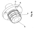
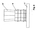
- Figs. 4a and 4b The principle of the tool is shown on Figs. 4a and 4b , whilst different applications of a cone shaped member 20, used as a mechanical force amplifier, fitted into the tool, to cause expansion of tool diameter to create beads in the pipe wall are shown in Figs. 4 - 6 .
- Fig. 7a shows a tool with a hydraulic force amplifier.
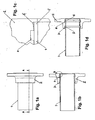
- Figs. 1a - 1d show that an outermost portion 2' of the coupling element 2 against which pipe end 1' rests is flared outward. This is to allow the tool to give the pipe end 1' an overbending outwards, which is necessary because the pipe end, as mentioned, will otherwise tend to taper inwards. Thus, the pipe 1 will appear almost straight after the beads 5, 6 have been pressed, as can be seen in the section shown in Fig. 1d .
- the cylindrical part of the coupling element 2; 2" as shown on Figs. 1 , 2 and 3 may advantageously be quite thin-walled. To a certain extent, the wall will then be resilient and yield a little during the pressing operation, and this will then mean that afterwards it is under inward tension and thus provides further pressure in the connection where the pipe 1 is in tension outwards.
- the principle of the tool is based on a plurality of segments 10, each having circle segment ridges 11 intended for being pressed out towards the inside of the pipe wall and thus forming the beads 5, 6 first.
- the cylinder segment parts 13 of each of the segments forming a cylindrical assembly of segments is pressed against the inside of the pipe at the portions thereof located sideways relative to the beads 5, 6 to prevent said portions from buckling inwards.
- Figs. 3a - 3d show the pipe 1 and the coupling 2 before the pressing operation
- FIG. 9 is an enlarged view of an intermediate stage during the pressing where the aforementioned buckled-in areas 1" of the pipe sideways relative to the beads 5, 6 can be seen.
- Figs. 3c and 3d it is seen that the cylindrical parts 13 of the segments 10 have pressed the buckled-in areas 1" back towards the coupling element 2 so that they lie almost flush with the inside wall of the pipe and its diameter.
- This after-pressing gives a powerful radial tensioning effect in the pipe which increases the contact pressure between pipe 1 and coupling element 2 the sealing points between beads 5, 6 and grooves 3, 4, and prevents the retraction of the pipe 1 as mentioned above when referring to plain ridges as previously described in, for example, DE 3144385 .
- a projection 14 is located innermost on the segments 10, i.e. close to a tool element flange 21, said projection 14 intended to cause pressure against the end 1"' of the pipe, as indicated also on fig. 9 .
- a recess 15 which may be made in the form of a bevel edge or a cut-out.
- This cut-out 15 can, for some uses, be partially filled with sealing material, or it may have an O-ring fitted therein.
- This special design of the tool and the coupling element has been found to be necessary in order to prevent the pipe from tapering or buckling inwards as previously mentioned.
- the segments 10 and especially the ridges 11 are subjected to extremely large stresses during the pressing operation and are therefore made of hardened steel. Consequently large radial forces are also required to operate the segments 10.
- the pressing of a connection between a coupling element 2 and a steel pipe 1 with an outer diameter of 76 mm and a wall thickness of 3.2 mm as shown on Figs. 1d , 2a and 2b by using eight segments 10 would require a radial force per segment of about 200 kN, in total a required force of about 1600 kN.
- Fig. 5a shows the tool with segments 10 and with a circular cone 20 acting as force amplifier
- Fig. 5b shows the tool with the cone 20 drawn in and the segments 10 in expanded position
- Fig. 6 shows the same tool with a polygonal pyramid 20' acting as force amplifier.
- Figs. 7a and 7b show a tool with hydraulically operated segments 22.
- a segment 22 is shown separately and it can be seen that the segment 22 is fastened to a piston 27 which can move in a corresponding cylinder 28 in a housing 24 which is filled with oil.
- the segments 22 have circle sector ridges 23 to create beads.
- the illustrated tool has a total of eight pistons 27 and eight cylinders 28. When a rod 25 is pressed into the housing, the oil in the housing 24 will press the pistons 27 outwards. The greater the diameter of the piston 27 in relation to the diameter of the rod 25, the greater the force amplification.
- Reference numeral 21 denotes a tool attachment flange, the flange having a plurality of attachment holes 26.
- the invention is suitable for couplings as shown on Figs. 8a and 8b where a coupling element 30 has an outer surface being part of a spherical surface, the coupling element 30 to be fastened to the pipe 1 and where a two-part flange has parts 30', 30" which can be joined to each other by screw action attachment, the two parts 30', 30" located on each side of the coupling element and facing one another.
- the flange with its flange parts 30', 30" will then be capable of being mounted at an angle which can be variably set relative to the pipe.
- the flange with is parts 30', 30" will either be freely movable, even after screwing the flange parts 30', 30" together, or will be such that it is locked to the coupling element 30 when the flange 30', 30" is tightened to another flange (not shown).
Landscapes
- Engineering & Computer Science (AREA)
- General Engineering & Computer Science (AREA)
- Mechanical Engineering (AREA)
- Non-Disconnectible Joints And Screw-Threaded Joints (AREA)
- Mutual Connection Of Rods And Tubes (AREA)
- Butt Welding And Welding Of Specific Article (AREA)
- Flanged Joints, Insulating Joints, And Other Joints (AREA)
- Joining Of Building Structures In Genera (AREA)
- Media Introduction/Drainage Providing Device (AREA)
- Conveying And Assembling Of Building Elements In Situ (AREA)
Claims (6)
- Verfahren zur Verbindung von einem Kupplungselement, z. B. einer Verbindungsflanschvorrichtung, mit einem Rohr, wobei das genannte Kupplungselement das Rohr umgibt und Rillen aufweist, die gegen das Rohr gerichtet und für die Aufnahme von einer entsprechenden Mehrheit von Wulsten, die sich am Rohr befinden, ausgebildet sind, durch folgende Schritte gekennzeichnet:- Erstellen des genannten Kupplungselements zur Umgebung des Rohrs an einem Endbereich hiervon,- Erstellen von einer ersten und zweckbestimmten radialbestimmten Anpresseinwirkung an der inneren Wand des Rohrs an axialen Stellen am Rohr entsprechend der Position von genannten Rillen am umgebenden Kupplungselement, um das Rohr hier zu deformieren und um genannte Wulsten zu erzeugen und in die genannten Rillen treten zu lassen und- Erstellen von einer ersten und zweckbestimmten radialbestimmten Nach-Anpresswirkung an der inneren Wand des Rohrs an gebogenen Stellen der Rohrwand" die natürlich zwischen und neben den hergestellten Wulsten vorkommen, während und verursacht von der ersten Anpresswirkung, um eine Nach-Anpresswirkung von den genannten Bereichen in Richtung nach außen und dadurch das Entstehen einer Spannung nach außen im Rohr an der Position des Kupplungselements zu erzeugen,
- Werkzeug zur Verbindung eines Kupplungselements, z. B. einer Verbindungsflanschvorrichtung, mit einem Rohr, genanntes Kupplungselement ist für Umgebung des Rohrs vorgesehen und hat Rillen, die gegen das Rohr gerichtet sind, und die für die Aufnahme einer entsprechenden Mehrheit von Wulsten, die sich am Rohr befinden, ausgebildet sind, durch folgendes gekennzeichnet:- dass das Werkzeug eine Mehrheit von axial getrennten, radial bewegbaren Segmenten (10) aufweist, jedes Segment hat eine Mehrheit von kreisausschnittförmigen Rippen, genannte Mehrheit von Segmenten bilden dadurch auf der Außenseite herausragende Rippen (11), die imstande sind, die Wand des Rohrs durch eine erste Anpresswirkung zu deformieren, um auf der Außenseite des Rohrs periphere Wulsten (5; 6) in der Wand des Rohrs zu erstellen, und um genannte Wulsten (5;6) in entsprechende Rillen (3; 4) im Kupplungselement eingreifen zu lassen, und- dass die Segmente auf der Außenseite herausragende Abschnitte (13) neben und zwischen den Rippen haben, genannte Abschnitte (13) sollen in einer zweiten, anschließenden Anpresswirkung eine Nach-Anpresswirkung an gebogenen Stellen, die natürlich in der Wand des Rohrs zwischen und neben den Wulsten während der ersten Anpresswirkung vorkommen, verursachen, um eine Spannung nach außen im Rohr an der Position vom Kupplungselement zu erzeugen
- Ein Werkzeug nach Anspruch 2, dadurch gekennzeichnet,- dass ein Teil der Segmente, die axial mit dem Rohrende fluchten müssen, einen Vorsprung (14) aufweist, der konfiguriert ist, um das Rohrende etwas weiter als der eigentliche Durchmesser des Rohrs auszudrücken.
- Ein Werkzeug nach Anspruch 2 oder 3, dadurch gekennzeichnet,- dass die Segmente einen internen kegelförmigen oder mehreckigen pyramidenförmigen Raum bilden, und- dass ein Kegel oder eine mehreckige Pyramide intern von und koaxial mit den Segmenten lokalisierbar ist, genannter Kegel oder genannte Pyramide verursachen, wenn in Richtung eines engen Endes von der genannten Form gezogen, eine radiale Bewegung der Segmente nach außen.
- Ein Kupplungselement, das mit einem Rohr verknüpfbar ist, genanntes Kupplungselement ist für Umgebung des Rohrs eingerichtet und hat Rillen, die gegen das Rohr gerichtet und für die Aufnahme von einer entsprechenden Mehrheit von Wulsten, die sich am Rohr befinden, gestaltet sind, für Anwendung mit einem Werkzeug nach den Ansprüchen 2, 3 und 4, vorgesehen, dadurch gekennzeichnet- dass das Kupplungselement am vordersten Abschnitt eine Vertiefung hat, deren Durchmesser größer der Außendurchmesser des Rohres ist, wobei das Kupplungselement bei Umgebung vom Rohr und genannter Vertiefung mit dem Rohrende angepasst ist, das Rohrende kann durch eine Biegewirkung nach außen in die genannte Vertiefung gepresst werden.
- Ein Kupplungselement nach Anspruch 5 dadurch gekennzeichnet, dass ein Teil von der äußeren Oberfläche des Kupplungselements (30) sphärisch so gestaltet ist, dass eine zweiteilige Flanscheinheit mit internem Raum hiervon auf die Oberfläche des Kupplungselements geklemmt werden kann, womit eine längslaufende Achse durch den genannten zweiteiligen Flansch winkelmässig einstellbar bezüglich einer längslaufenden Achse des Rohrs ist.
Priority Applications (2)
| Application Number | Priority Date | Filing Date | Title |
|---|---|---|---|
| PL05730356T PL1727632T3 (pl) | 2004-03-24 | 2005-03-18 | Sposób i urządzenie do łączenia na zimno kołnierzy i elementów łączących z rurami |
| SI200530758T SI1727632T1 (sl) | 2004-03-24 | 2005-03-18 | Postopek in naprava za hladno spajanje prirobnic in sklopnih elementov na cevi |
Applications Claiming Priority (2)
| Application Number | Priority Date | Filing Date | Title |
|---|---|---|---|
| NO20041215A NO20041215D0 (no) | 2004-03-24 | 2004-03-24 | Metode for anrekninger for festing av koblingselementer til ror |
| PCT/NO2005/000093 WO2005089975A1 (en) | 2004-03-24 | 2005-03-18 | Method and apparatus for cold joining flanges and couplings elements to pipes |
Publications (2)
| Publication Number | Publication Date |
|---|---|
| EP1727632A1 EP1727632A1 (de) | 2006-12-06 |
| EP1727632B1 true EP1727632B1 (de) | 2009-05-20 |
Family
ID=34859222
Family Applications (1)
| Application Number | Title | Priority Date | Filing Date |
|---|---|---|---|
| EP05730356A Expired - Lifetime EP1727632B1 (de) | 2004-03-24 | 2005-03-18 | Verfahren und vorrichtung zur kaltverbindung von flanschen und kupplungselementen mit rohren |
Country Status (23)
| Country | Link |
|---|---|
| US (2) | US8056208B2 (de) |
| EP (1) | EP1727632B1 (de) |
| JP (1) | JP5010462B2 (de) |
| KR (1) | KR100818682B1 (de) |
| CN (1) | CN100509201C (de) |
| AT (1) | ATE431765T1 (de) |
| AU (1) | AU2005224981B2 (de) |
| BR (1) | BRPI0509130B1 (de) |
| CA (1) | CA2560556C (de) |
| CY (1) | CY1109315T1 (de) |
| DE (1) | DE602005014547D1 (de) |
| DK (1) | DK1727632T3 (de) |
| EA (1) | EA009419B1 (de) |
| EG (1) | EG24702A (de) |
| ES (1) | ES2329694T3 (de) |
| HR (1) | HRP20090440T1 (de) |
| MX (1) | MXPA06010874A (de) |
| NO (2) | NO20041215D0 (de) |
| PL (1) | PL1727632T3 (de) |
| PT (1) | PT1727632E (de) |
| RS (1) | RS51184B (de) |
| SI (1) | SI1727632T1 (de) |
| WO (1) | WO2005089975A1 (de) |
Families Citing this family (18)
| Publication number | Priority date | Publication date | Assignee | Title |
|---|---|---|---|---|
| CN101362177B (zh) * | 2008-09-02 | 2012-07-18 | 王林秋 | 软管弯头芯子的成型工艺 |
| KR101053127B1 (ko) * | 2008-12-01 | 2011-08-02 | 김광희 | 금속 파이프용 이음구 |
| US9192975B2 (en) * | 2009-01-30 | 2015-11-24 | Larry John Verbowski | Vehicle suspension module |
| KR100924735B1 (ko) * | 2009-03-12 | 2009-11-04 | (주)로커스 | 냉매용 피팅 장치 |
| KR200463085Y1 (ko) | 2011-01-05 | 2012-10-16 | 한전케이피에스 주식회사 | 튜브 작업용 공구장치 |
| US8857036B2 (en) * | 2011-03-07 | 2014-10-14 | GM Global Technology Operations LLC | Leak-tight connection between pipe and port |
| US9199295B2 (en) * | 2012-09-10 | 2015-12-01 | The Boeing Company | Roller swage method and apparatus |
| AU2014236478B2 (en) * | 2013-03-14 | 2018-11-22 | Connector Subsea Solutions (UK) Ltd | Pipe end seal assembly |
| KR101654238B1 (ko) * | 2015-11-23 | 2016-09-06 | 정우금속공업 주식회사 | 배관 연결장치 및 이의 제조방법 |
| BR102016013772B1 (pt) * | 2016-06-14 | 2021-07-13 | Embraco Industria De Compressores E Soluqoes Em Refrigeraqao Ltda. | Aperfeiqoamento introduzido em sistema para conexao de tubos de descarga de fluido refrigerante em tampas de cilindro de compressores hermeticos, e correspondente processo de execuqao |
| CN105921630A (zh) * | 2016-06-29 | 2016-09-07 | 长沙天和钻具机械有限公司 | 一种同心钻具扩孔套组件的装配工艺 |
| CN107570613B (zh) * | 2017-08-31 | 2019-08-06 | 哈尔滨工程大学 | 水下冷成型管道连接装置 |
| DE102018108411B4 (de) * | 2018-04-10 | 2022-06-30 | Scherdel Innotec Forschungs- Und Entwicklungs-Gmbh | Verfahren zum lötfreien Ausbilden eines Anschluss-Stutzens an einem Rohrende sowie Rohr mit einem lötfrei ausgebildeten Anschluss-Stutzen an einem Rohrende |
| CN110445291A (zh) * | 2018-05-03 | 2019-11-12 | 舍弗勒技术股份两合公司 | 冷却水套、冷却装置及制造冷却水套的方法 |
| KR102286715B1 (ko) * | 2020-06-17 | 2021-08-09 | 최봉록 | 파이프 엘보 제조방법 |
| CN111604663B (zh) * | 2020-06-22 | 2024-07-16 | 杭州富阳伟立自动化科技有限公司 | 一种管件与基座的装配装置 |
| CN115519312B (zh) * | 2022-10-14 | 2024-11-08 | 常熟市华德粉末冶金有限公司 | 通孔用治具及通孔方法 |
| WO2025221238A1 (en) * | 2024-04-15 | 2025-10-23 | Carolina Components Group, Inc. | Heat exchanger tubing assembly and conductive casing |
Family Cites Families (27)
| Publication number | Priority date | Publication date | Assignee | Title |
|---|---|---|---|---|
| US1753005A (en) * | 1926-08-05 | 1930-04-01 | Eureka Fire Hose Mfg Company | Method of uniting tubular members |
| US2252274A (en) | 1938-09-07 | 1941-08-12 | Kellogg M W Co | Tube connecting device and method |
| GB841869A (en) * | 1955-10-06 | 1960-07-20 | Thos P Headland Ltd | Improvements in or relating to pipe couplings |
| US3575447A (en) * | 1969-03-24 | 1971-04-20 | Gen Motors Corp | Tube fitting |
| US3730567A (en) * | 1970-07-08 | 1973-05-01 | Axial Corp | Coupling sleeve |
| US4154464A (en) * | 1971-06-16 | 1979-05-15 | Stary Walter E | Tube holding means in a heat exchanger |
| SE7505866L (sv) | 1974-06-06 | 1975-12-08 | Boeing Co | Kopplingshylsa |
| BR7600832A (pt) * | 1975-05-01 | 1976-11-09 | Caterpillar Tractor Co | Montagem de tubo junta preparada para um ajustador e metodo para juntar mecanicamente um ajustador a extremidade de um comprimento de tubo metalico |
| FR2353785A1 (fr) | 1976-06-01 | 1977-12-30 | Euratom | Procede de realisation de l'etancheite d'un raccord tubulaire et raccord tubulaire etanche |
| JPS5630689U (de) * | 1979-08-17 | 1981-03-25 | ||
| JPS5630689A (en) | 1979-08-21 | 1981-03-27 | Doryokuro Kakunenryo | Nuclear fuel element with heattgeneration temperature measuring instrumentation |
| DE2945474C2 (de) | 1979-11-10 | 1983-02-03 | Vaw-Leichtmetall Gmbh, 5300 Bonn | Rohranschluß zum Verbinden von Rohren mit Flanschen, Voll- oder Hohlprofilen und Verfahren zur Herstellung des Rohranschlusses |
| FR2475949A1 (fr) | 1980-02-15 | 1981-08-21 | Vallourec | Procede de dudgeonnage, dudgeon susceptible d'etre utilise pour la mise en oeuvre de ce procede, et assemblage obtenu a l'aide de ce procede |
| DE3144385C2 (de) | 1981-11-07 | 1983-10-20 | Deutsche Schachtbau- und Tiefbohr-Gesellschaft mbH, 4450 Lingen | Überschiebemuffe |
| JPS59147917A (ja) | 1983-02-09 | 1984-08-24 | Dowa:Kk | 気化バ−ナにおける給油装置 |
| JPS59147917U (ja) * | 1983-03-25 | 1984-10-03 | 市光工業株式会社 | リンクレバ−の球継手連結構造 |
| IT1174062B (it) | 1984-03-14 | 1987-07-01 | Nuovo Pignone Spa | Perfezionamenti nel metodo per la giunzione a tenuta di un manicotto ad una tubazione sottomarina posata a grande prfondita |
| ES8604434A1 (es) | 1984-07-13 | 1986-02-01 | Ormaechea Mujica Marcos | Procedimiento de fabricacion de zapatas para frenos |
| JPS6163330U (de) * | 1984-07-27 | 1986-04-30 | ||
| JPS61133229A (ja) | 1984-11-30 | 1986-06-20 | Hitachi Chem Co Ltd | 熱硬化性水性樹脂組成物の製造法 |
| JPS61133229U (de) * | 1985-02-01 | 1986-08-20 | ||
| US4934038A (en) * | 1989-09-15 | 1990-06-19 | Caterpillar Inc. | Method and apparatus for tube expansion |
| AU628743B2 (en) | 1990-06-22 | 1992-09-17 | Crane Enfield Metals Pty Limited | Expanding mandrel method and product produced thereby |
| US5335729A (en) * | 1992-05-11 | 1994-08-09 | Cooper Industries, Inc. | Tubular connection, method for making same, and tool therefor |
| JPH10318452A (ja) | 1997-05-16 | 1998-12-04 | Fuji Koatsu Furekishiburu Hoosu Kk | パイプと継手との接続装置 |
| RU2159689C2 (ru) * | 1998-12-04 | 2000-11-27 | Самарский государственный аэрокосмический университет им. акад. С.П. Королева | Способ закрепления труб в трубных решетках |
| US6517126B1 (en) | 2000-09-22 | 2003-02-11 | General Electric Company | Internal swage fitting |
-
2004
- 2004-03-24 NO NO20041215A patent/NO20041215D0/no not_active Application Discontinuation
-
2005
- 2005-03-18 DE DE602005014547T patent/DE602005014547D1/de not_active Expired - Lifetime
- 2005-03-18 HR HR20090440T patent/HRP20090440T1/hr unknown
- 2005-03-18 JP JP2007504902A patent/JP5010462B2/ja not_active Expired - Fee Related
- 2005-03-18 MX MXPA06010874A patent/MXPA06010874A/es active IP Right Grant
- 2005-03-18 SI SI200530758T patent/SI1727632T1/sl unknown
- 2005-03-18 CA CA2560556A patent/CA2560556C/en not_active Expired - Lifetime
- 2005-03-18 WO PCT/NO2005/000093 patent/WO2005089975A1/en not_active Ceased
- 2005-03-18 PT PT05730356T patent/PT1727632E/pt unknown
- 2005-03-18 ES ES05730356T patent/ES2329694T3/es not_active Expired - Lifetime
- 2005-03-18 RS RSP-2009/0365A patent/RS51184B/sr unknown
- 2005-03-18 PL PL05730356T patent/PL1727632T3/pl unknown
- 2005-03-18 AT AT05730356T patent/ATE431765T1/de active
- 2005-03-18 EP EP05730356A patent/EP1727632B1/de not_active Expired - Lifetime
- 2005-03-18 KR KR1020067022097A patent/KR100818682B1/ko not_active Expired - Fee Related
- 2005-03-18 CN CNB2005800166364A patent/CN100509201C/zh not_active Expired - Fee Related
- 2005-03-18 AU AU2005224981A patent/AU2005224981B2/en not_active Ceased
- 2005-03-18 BR BRPI0509130-6A patent/BRPI0509130B1/pt not_active IP Right Cessation
- 2005-03-18 DK DK05730356T patent/DK1727632T3/da active
- 2005-03-18 EA EA200601762A patent/EA009419B1/ru unknown
- 2005-03-18 US US10/599,162 patent/US8056208B2/en not_active Expired - Fee Related
-
2006
- 2006-09-24 EG EGNA2007000916 patent/EG24702A/xx active
- 2006-10-18 NO NO20064730A patent/NO338972B1/no not_active IP Right Cessation
-
2009
- 2009-08-18 CY CY20091100879T patent/CY1109315T1/el unknown
-
2010
- 2010-11-05 US US12/940,539 patent/US8474131B2/en not_active Expired - Lifetime
Also Published As
Similar Documents
| Publication | Publication Date | Title |
|---|---|---|
| US8474131B2 (en) | Apparatus for cold joining a coupling element to a pipe | |
| US8156630B2 (en) | Method of joining members | |
| US7065995B2 (en) | Expansion tool for expanding tube ends and pressing device comprising such an expansion tool | |
| JP2008303901A (ja) | ノンボルト継手構造およびノンボルト継手構造を形成する方法 | |
| JPH06264909A (ja) | 張力装置 | |
| EP3091261B1 (de) | Muffenadapter | |
| US6543817B1 (en) | Process for forming radially upset tube flange and tube connector assembly formed thereby | |
| US4043160A (en) | Internal tooling for swaging apparatus | |
| US6877779B2 (en) | Conduit connector and method | |
| EP0211454A1 (de) | Verfahren und Vorrichtung zur Herstellung einer gasdichten Verbindung und auf diese Weise hergestellte Verbindung | |
| HK1106471B (en) | Method and apparatus for cold joining flanges and couplings elements to pipes | |
| JP4549686B2 (ja) | バルジ成形装置とバルジ成形方法及びその成形品 | |
| RU2386888C1 (ru) | Соединение трубопроводов | |
| JPS5928602B2 (ja) | 筒状物の整径方法とその装置 | |
| JPH08233171A (ja) | 離脱防止管継手とその接合方法 | |
| JP7628626B2 (ja) | 配管ユニットを製作する装置を備えるシステム及び配管ユニットを製作する方法 | |
| RU2174886C2 (ru) | Способ закрепления труб в трубных решетках | |
| FI95167B (fi) | Käyttösylinteri | |
| RU2171154C2 (ru) | Способ закрепления труб в трубных решетках | |
| JPS62199235A (ja) | ベロ−ズのフランジ取付け方法 | |
| ZA200710650B (en) | Socket forming machine |
Legal Events
| Date | Code | Title | Description |
|---|---|---|---|
| PUAI | Public reference made under article 153(3) epc to a published international application that has entered the european phase |
Free format text: ORIGINAL CODE: 0009012 |
|
| 17P | Request for examination filed |
Effective date: 20061002 |
|
| AK | Designated contracting states |
Kind code of ref document: A1 Designated state(s): AT BE BG CH CY CZ DE DK EE ES FI FR GB GR HU IE IS IT LI LT LU MC NL PL PT RO SE SI SK TR |
|
| AX | Request for extension of the european patent |
Extension state: AL BA HR LV MK YU |
|
| GRAP | Despatch of communication of intention to grant a patent |
Free format text: ORIGINAL CODE: EPIDOSNIGR1 |
|
| GRAS | Grant fee paid |
Free format text: ORIGINAL CODE: EPIDOSNIGR3 |
|
| GRAA | (expected) grant |
Free format text: ORIGINAL CODE: 0009210 |
|
| AK | Designated contracting states |
Kind code of ref document: B1 Designated state(s): AT BE BG CH CY CZ DE DK EE ES FI FR GB GR HU IE IS IT LI LT LU MC NL PL PT RO SE SI SK TR |
|
| AX | Request for extension of the european patent |
Extension state: AL BA HR LV MK YU |
|
| REG | Reference to a national code |
Ref country code: GB Ref legal event code: FG4D |
|
| REG | Reference to a national code |
Ref country code: CH Ref legal event code: EP |
|
| REG | Reference to a national code |
Ref country code: IE Ref legal event code: FG4D |
|
| REF | Corresponds to: |
Ref document number: 602005014547 Country of ref document: DE Date of ref document: 20090702 Kind code of ref document: P |
|
| REG | Reference to a national code |
Ref country code: HR Ref legal event code: TUEP Ref document number: P20090440 Country of ref document: HR Ref country code: PT Ref legal event code: SC4A Free format text: AVAILABILITY OF NATIONAL TRANSLATION Effective date: 20090806 |
|
| REG | Reference to a national code |
Ref country code: RO Ref legal event code: EPE |
|
| REG | Reference to a national code |
Ref country code: DK Ref legal event code: T3 |
|
| REG | Reference to a national code |
Ref country code: SE Ref legal event code: TRGR |
|
| REG | Reference to a national code |
Ref country code: GR Ref legal event code: EP Ref document number: 20090402110 Country of ref document: GR |
|
| REG | Reference to a national code |
Ref country code: HR Ref legal event code: T1PR Ref document number: P20090440 Country of ref document: HR |
|
| REG | Reference to a national code |
Ref country code: EE Ref legal event code: FG4A Ref document number: E003446 Country of ref document: EE Effective date: 20090819 |
|
| REG | Reference to a national code |
Ref country code: PL Ref legal event code: T3 |
|
| REG | Reference to a national code |
Ref country code: ES Ref legal event code: FG2A Ref document number: 2329694 Country of ref document: ES Kind code of ref document: T3 |
|
| REG | Reference to a national code |
Ref country code: HU Ref legal event code: AG4A Ref document number: E006204 Country of ref document: HU |
|
| PLBE | No opposition filed within time limit |
Free format text: ORIGINAL CODE: 0009261 |
|
| STAA | Information on the status of an ep patent application or granted ep patent |
Free format text: STATUS: NO OPPOSITION FILED WITHIN TIME LIMIT |
|
| 26N | No opposition filed |
Effective date: 20100223 |
|
| PG25 | Lapsed in a contracting state [announced via postgrant information from national office to epo] |
Ref country code: LU Free format text: LAPSE BECAUSE OF NON-PAYMENT OF DUE FEES Effective date: 20100318 |
|
| REG | Reference to a national code |
Ref country code: FR Ref legal event code: PLFP Year of fee payment: 12 |
|
| REG | Reference to a national code |
Ref country code: FR Ref legal event code: PLFP Year of fee payment: 13 |
|
| REG | Reference to a national code |
Ref country code: FR Ref legal event code: PLFP Year of fee payment: 14 |
|
| REG | Reference to a national code |
Ref country code: HR Ref legal event code: ODRP Ref document number: P20090440 Country of ref document: HR Payment date: 20190218 Year of fee payment: 15 |
|
| REG | Reference to a national code |
Ref country code: HR Ref legal event code: ODRP Ref document number: P20090440 Country of ref document: HR Payment date: 20200218 Year of fee payment: 16 |
|
| REG | Reference to a national code |
Ref country code: HR Ref legal event code: ODRP Ref document number: P20090440 Country of ref document: HR Payment date: 20210316 Year of fee payment: 17 |
|
| REG | Reference to a national code |
Ref country code: HR Ref legal event code: ODRP Ref document number: P20090440 Country of ref document: HR Payment date: 20220218 Year of fee payment: 18 |
|
| PGFP | Annual fee paid to national office [announced via postgrant information from national office to epo] |
Ref country code: LT Payment date: 20220215 Year of fee payment: 18 Ref country code: HU Payment date: 20220223 Year of fee payment: 18 Ref country code: FI Payment date: 20220310 Year of fee payment: 18 Ref country code: CH Payment date: 20220310 Year of fee payment: 18 |
|
| PGFP | Annual fee paid to national office [announced via postgrant information from national office to epo] |
Ref country code: TR Payment date: 20220224 Year of fee payment: 18 Ref country code: SK Payment date: 20220224 Year of fee payment: 18 Ref country code: RO Payment date: 20220218 Year of fee payment: 18 Ref country code: PT Payment date: 20220302 Year of fee payment: 18 Ref country code: PL Payment date: 20220218 Year of fee payment: 18 Ref country code: CZ Payment date: 20220218 Year of fee payment: 18 |
|
| PGFP | Annual fee paid to national office [announced via postgrant information from national office to epo] |
Ref country code: SI Payment date: 20220225 Year of fee payment: 18 |
|
| PGFP | Annual fee paid to national office [announced via postgrant information from national office to epo] |
Ref country code: SE Payment date: 20220603 Year of fee payment: 18 Ref country code: NL Payment date: 20220630 Year of fee payment: 18 Ref country code: MC Payment date: 20220623 Year of fee payment: 18 Ref country code: IT Payment date: 20220620 Year of fee payment: 18 Ref country code: IE Payment date: 20220611 Year of fee payment: 18 Ref country code: GB Payment date: 20220617 Year of fee payment: 18 Ref country code: EE Payment date: 20220628 Year of fee payment: 18 Ref country code: DK Payment date: 20220615 Year of fee payment: 18 Ref country code: DE Payment date: 20220621 Year of fee payment: 18 Ref country code: CY Payment date: 20220316 Year of fee payment: 18 Ref country code: BG Payment date: 20220603 Year of fee payment: 18 |
|
| PGFP | Annual fee paid to national office [announced via postgrant information from national office to epo] |
Ref country code: GR Payment date: 20220623 Year of fee payment: 18 Ref country code: BE Payment date: 20220613 Year of fee payment: 18 Ref country code: AT Payment date: 20220621 Year of fee payment: 18 |
|
| PGFP | Annual fee paid to national office [announced via postgrant information from national office to epo] |
Ref country code: IS Payment date: 20220623 Year of fee payment: 18 Ref country code: FR Payment date: 20220613 Year of fee payment: 18 |
|
| PGFP | Annual fee paid to national office [announced via postgrant information from national office to epo] |
Ref country code: ES Payment date: 20220831 Year of fee payment: 18 |
|
| REG | Reference to a national code |
Ref country code: HR Ref legal event code: PBON Ref document number: P20090440 Country of ref document: HR Effective date: 20230318 |
|
| REG | Reference to a national code |
Ref country code: DE Ref legal event code: R119 Ref document number: 602005014547 Country of ref document: DE |
|
| REG | Reference to a national code |
Ref country code: LT Ref legal event code: MM4D Effective date: 20230318 |
|
| REG | Reference to a national code |
Ref country code: EE Ref legal event code: MM4A Ref document number: E003446 Country of ref document: EE Effective date: 20230331 |
|
| PG25 | Lapsed in a contracting state [announced via postgrant information from national office to epo] |
Ref country code: RO Free format text: LAPSE BECAUSE OF NON-PAYMENT OF DUE FEES Effective date: 20230318 Ref country code: PT Free format text: LAPSE BECAUSE OF NON-PAYMENT OF DUE FEES Effective date: 20230918 Ref country code: MC Free format text: LAPSE BECAUSE OF NON-PAYMENT OF DUE FEES Effective date: 20230331 Ref country code: FI Free format text: LAPSE BECAUSE OF NON-PAYMENT OF DUE FEES Effective date: 20230318 Ref country code: CZ Free format text: LAPSE BECAUSE OF NON-PAYMENT OF DUE FEES Effective date: 20230318 Ref country code: CY Free format text: LAPSE BECAUSE OF NON-PAYMENT OF DUE FEES Effective date: 20230318 |
|
| REG | Reference to a national code |
Ref country code: SE Ref legal event code: EUG Ref country code: CH Ref legal event code: PL |
|
| REG | Reference to a national code |
Ref country code: DK Ref legal event code: EBP Effective date: 20230331 |
|
| REG | Reference to a national code |
Ref country code: SK Ref legal event code: MM4A Ref document number: E 5989 Country of ref document: SK Effective date: 20230318 Ref country code: NL Ref legal event code: MM Effective date: 20230401 |
|
| REG | Reference to a national code |
Ref country code: AT Ref legal event code: MM01 Ref document number: 431765 Country of ref document: AT Kind code of ref document: T Effective date: 20230318 |
|
| GBPC | Gb: european patent ceased through non-payment of renewal fee |
Effective date: 20230318 |
|
| REG | Reference to a national code |
Ref country code: BE Ref legal event code: MM Effective date: 20230331 |
|
| PG25 | Lapsed in a contracting state [announced via postgrant information from national office to epo] |
Ref country code: NL Free format text: LAPSE BECAUSE OF NON-PAYMENT OF DUE FEES Effective date: 20230401 |
|
| REG | Reference to a national code |
Ref country code: SI Ref legal event code: KO00 Effective date: 20231123 |
|
| PG25 | Lapsed in a contracting state [announced via postgrant information from national office to epo] |
Ref country code: SK Free format text: LAPSE BECAUSE OF NON-PAYMENT OF DUE FEES Effective date: 20230318 |
|
| REG | Reference to a national code |
Ref country code: IE Ref legal event code: MM4A |
|
| PG25 | Lapsed in a contracting state [announced via postgrant information from national office to epo] |
Ref country code: GR Free format text: LAPSE BECAUSE OF NON-PAYMENT OF DUE FEES Effective date: 20231009 Ref country code: GB Free format text: LAPSE BECAUSE OF NON-PAYMENT OF DUE FEES Effective date: 20230318 |
|
| PG25 | Lapsed in a contracting state [announced via postgrant information from national office to epo] |
Ref country code: SK Free format text: LAPSE BECAUSE OF NON-PAYMENT OF DUE FEES Effective date: 20230318 Ref country code: SI Free format text: LAPSE BECAUSE OF NON-PAYMENT OF DUE FEES Effective date: 20230319 Ref country code: SE Free format text: LAPSE BECAUSE OF NON-PAYMENT OF DUE FEES Effective date: 20230319 Ref country code: LT Free format text: LAPSE BECAUSE OF NON-PAYMENT OF DUE FEES Effective date: 20230318 Ref country code: LI Free format text: LAPSE BECAUSE OF NON-PAYMENT OF DUE FEES Effective date: 20230331 Ref country code: IE Free format text: LAPSE BECAUSE OF NON-PAYMENT OF DUE FEES Effective date: 20230318 Ref country code: HU Free format text: LAPSE BECAUSE OF NON-PAYMENT OF DUE FEES Effective date: 20230319 Ref country code: GR Free format text: LAPSE BECAUSE OF NON-PAYMENT OF DUE FEES Effective date: 20231009 Ref country code: GB Free format text: LAPSE BECAUSE OF NON-PAYMENT OF DUE FEES Effective date: 20230318 Ref country code: FR Free format text: LAPSE BECAUSE OF NON-PAYMENT OF DUE FEES Effective date: 20230331 Ref country code: EE Free format text: LAPSE BECAUSE OF NON-PAYMENT OF DUE FEES Effective date: 20230331 Ref country code: DE Free format text: LAPSE BECAUSE OF NON-PAYMENT OF DUE FEES Effective date: 20231003 Ref country code: CH Free format text: LAPSE BECAUSE OF NON-PAYMENT OF DUE FEES Effective date: 20230331 Ref country code: AT Free format text: LAPSE BECAUSE OF NON-PAYMENT OF DUE FEES Effective date: 20230318 |
|
| PG25 | Lapsed in a contracting state [announced via postgrant information from national office to epo] |
Ref country code: BE Free format text: LAPSE BECAUSE OF NON-PAYMENT OF DUE FEES Effective date: 20230331 |
|
| PG25 | Lapsed in a contracting state [announced via postgrant information from national office to epo] |
Ref country code: IT Free format text: LAPSE BECAUSE OF NON-PAYMENT OF DUE FEES Effective date: 20230318 Ref country code: DK Free format text: LAPSE BECAUSE OF NON-PAYMENT OF DUE FEES Effective date: 20230331 |
|
| REG | Reference to a national code |
Ref country code: ES Ref legal event code: FD2A Effective date: 20240430 |
|
| PG25 | Lapsed in a contracting state [announced via postgrant information from national office to epo] |
Ref country code: ES Free format text: LAPSE BECAUSE OF NON-PAYMENT OF DUE FEES Effective date: 20230319 |
|
| PG25 | Lapsed in a contracting state [announced via postgrant information from national office to epo] |
Ref country code: ES Free format text: LAPSE BECAUSE OF NON-PAYMENT OF DUE FEES Effective date: 20230319 |
|
| PG25 | Lapsed in a contracting state [announced via postgrant information from national office to epo] |
Ref country code: PL Free format text: LAPSE BECAUSE OF NON-PAYMENT OF DUE FEES Effective date: 20230318 |
|
| PG25 | Lapsed in a contracting state [announced via postgrant information from national office to epo] |
Ref country code: PL Free format text: LAPSE BECAUSE OF NON-PAYMENT OF DUE FEES Effective date: 20230318 |
|
| PG25 | Lapsed in a contracting state [announced via postgrant information from national office to epo] |
Ref country code: BG Free format text: LAPSE BECAUSE OF NON-PAYMENT OF DUE FEES Effective date: 20230318 |
|
| PG25 | Lapsed in a contracting state [announced via postgrant information from national office to epo] |
Ref country code: BG Free format text: LAPSE BECAUSE OF NON-PAYMENT OF DUE FEES Effective date: 20230318 |
|
| PG25 | Lapsed in a contracting state [announced via postgrant information from national office to epo] |
Ref country code: IS Free format text: LAPSE BECAUSE OF NON-PAYMENT OF DUE FEES Effective date: 20231002 |