EP1728023B1 - Lampe transportable - Google Patents
Lampe transportable Download PDFInfo
- Publication number
- EP1728023B1 EP1728023B1 EP05738427A EP05738427A EP1728023B1 EP 1728023 B1 EP1728023 B1 EP 1728023B1 EP 05738427 A EP05738427 A EP 05738427A EP 05738427 A EP05738427 A EP 05738427A EP 1728023 B1 EP1728023 B1 EP 1728023B1
- Authority
- EP
- European Patent Office
- Prior art keywords
- lamp
- tensioning
- tensioning means
- clamping
- aid
- Prior art date
- Legal status (The legal status is an assumption and is not a legal conclusion. Google has not performed a legal analysis and makes no representation as to the accuracy of the status listed.)
- Expired - Lifetime
Links
Images

Classifications
-
- F—MECHANICAL ENGINEERING; LIGHTING; HEATING; WEAPONS; BLASTING
- F21—LIGHTING
- F21L—LIGHTING DEVICES OR SYSTEMS THEREOF, BEING PORTABLE OR SPECIALLY ADAPTED FOR TRANSPORTATION
- F21L14/00—Electric lighting devices without a self-contained power source, e.g. for mains connection
-
- F—MECHANICAL ENGINEERING; LIGHTING; HEATING; WEAPONS; BLASTING
- F21—LIGHTING
- F21V—FUNCTIONAL FEATURES OR DETAILS OF LIGHTING DEVICES OR SYSTEMS THEREOF; STRUCTURAL COMBINATIONS OF LIGHTING DEVICES WITH OTHER ARTICLES, NOT OTHERWISE PROVIDED FOR
- F21V1/00—Shades for light sources, i.e. lampshades for table, floor, wall or ceiling lamps
- F21V1/02—Frames
- F21V1/06—Frames foldable or collapsible
-
- F—MECHANICAL ENGINEERING; LIGHTING; HEATING; WEAPONS; BLASTING
- F21—LIGHTING
- F21V—FUNCTIONAL FEATURES OR DETAILS OF LIGHTING DEVICES OR SYSTEMS THEREOF; STRUCTURAL COMBINATIONS OF LIGHTING DEVICES WITH OTHER ARTICLES, NOT OTHERWISE PROVIDED FOR
- F21V17/00—Fastening of component parts of lighting devices, e.g. shades, globes, refractors, reflectors, filters, screens, grids or protective cages
- F21V17/007—Fastening of component parts of lighting devices, e.g. shades, globes, refractors, reflectors, filters, screens, grids or protective cages with provision for shipment or storage
-
- F—MECHANICAL ENGINEERING; LIGHTING; HEATING; WEAPONS; BLASTING
- F21—LIGHTING
- F21V—FUNCTIONAL FEATURES OR DETAILS OF LIGHTING DEVICES OR SYSTEMS THEREOF; STRUCTURAL COMBINATIONS OF LIGHTING DEVICES WITH OTHER ARTICLES, NOT OTHERWISE PROVIDED FOR
- F21V23/00—Arrangement of electric circuit elements in or on lighting devices
- F21V23/04—Arrangement of electric circuit elements in or on lighting devices the elements being switches
-
- F—MECHANICAL ENGINEERING; LIGHTING; HEATING; WEAPONS; BLASTING
- F21—LIGHTING
- F21V—FUNCTIONAL FEATURES OR DETAILS OF LIGHTING DEVICES OR SYSTEMS THEREOF; STRUCTURAL COMBINATIONS OF LIGHTING DEVICES WITH OTHER ARTICLES, NOT OTHERWISE PROVIDED FOR
- F21V25/00—Safety devices structurally associated with lighting devices
- F21V25/02—Safety devices structurally associated with lighting devices coming into action when lighting device is disturbed, dismounted, or broken
- F21V25/04—Safety devices structurally associated with lighting devices coming into action when lighting device is disturbed, dismounted, or broken breaking the electric circuit
-
- F—MECHANICAL ENGINEERING; LIGHTING; HEATING; WEAPONS; BLASTING
- F21—LIGHTING
- F21V—FUNCTIONAL FEATURES OR DETAILS OF LIGHTING DEVICES OR SYSTEMS THEREOF; STRUCTURAL COMBINATIONS OF LIGHTING DEVICES WITH OTHER ARTICLES, NOT OTHERWISE PROVIDED FOR
- F21V3/00—Globes; Bowls; Cover glasses
- F21V3/02—Globes; Bowls; Cover glasses characterised by the shape
- F21V3/023—Chinese lanterns; Balloons
-
- F—MECHANICAL ENGINEERING; LIGHTING; HEATING; WEAPONS; BLASTING
- F21—LIGHTING
- F21L—LIGHTING DEVICES OR SYSTEMS THEREOF, BEING PORTABLE OR SPECIALLY ADAPTED FOR TRANSPORTATION
- F21L14/00—Electric lighting devices without a self-contained power source, e.g. for mains connection
- F21L14/02—Electric lighting devices without a self-contained power source, e.g. for mains connection capable of hand-held use, e.g. inspection lamps
-
- F—MECHANICAL ENGINEERING; LIGHTING; HEATING; WEAPONS; BLASTING
- F21—LIGHTING
- F21S—NON-PORTABLE LIGHTING DEVICES; SYSTEMS THEREOF; VEHICLE LIGHTING DEVICES SPECIALLY ADAPTED FOR VEHICLE EXTERIORS
- F21S6/00—Lighting devices intended to be free-standing
-
- F—MECHANICAL ENGINEERING; LIGHTING; HEATING; WEAPONS; BLASTING
- F21—LIGHTING
- F21W—INDEXING SCHEME ASSOCIATED WITH SUBCLASSES F21K, F21L, F21S and F21V, RELATING TO USES OR APPLICATIONS OF LIGHTING DEVICES OR SYSTEMS
- F21W2131/00—Use or application of lighting devices or systems not provided for in codes F21W2102/00-F21W2121/00
- F21W2131/10—Outdoor lighting
- F21W2131/1005—Outdoor lighting of working places, building sites or the like
Definitions
- the invention relates to a luminaire with a folding screen provided at least partially with a reflective layer, wherein one or more movable tensioning means are provided, which span the folding screen and the folding screen encloses a lighting means in the tensioned and in the relaxed state.
- Transportable lights with a folding screen are known as hand or floor lights and are preferably used for temporary illumination of rooms or exposed areas. Depending on the intended use, it can be lights with low power or even lights up to 1,000 watts and more. The latter are preferably used in open-air areas for the illumination of, for example, a construction site, accident sites, large-scale damage situations or sports events.
- the invention has for its object to provide a portable lamp available, which can not be destroyed by heat damage.
- the object according to the invention is achieved in that at least one device is provided which monitors the tensioned state of the folding screen and / or the temperature of the lighting means and at least one of the devices locks the clamping means of the folding screen as a function of the temperature of the lighting means.
- a safety device which prevents the simultaneous relaxation of the tensioning mechanism and warm phase of the lamp, ensures that the portable lamp can not be destroyed by heat damage, so that the lamp can not be turned on in the relaxed state of Faltless or relaxation of the folding screen can be done after heating , This results in the advantage that an inadvertently energized light bulb does not destroy the folding screen by heat.
- one of the elements of the clamping means in the relaxed state of the folding screen trigger an electrical breaker.
- the safety device may be a circuit breaker, which is arranged in the portable lamp, that this is triggered by a movable element of the clamping means in the relaxed state.
- the power supply of the lamp is interrupted in this case.
- the breaker is designed so that it closes the circuit only in the fully tensioned state of the folding screen. This prevents the light bulb from destroying an incompletely tensioned screen when switched on prematurely.
- the device according to the invention is not limited to a power interruption, which prevents the light source can be turned on in the relaxed state of the folding screen, but may also be a device that by the light itself, for example by heating by the light source, prevents the Clamping means can be relaxed.
- An element which locks the clamping means of the folding screen by the thermal expansion thus has the advantage that this is independent of a power supply, for example, after switching off the lamp.
- the locking device consists advantageously of two mutually encompassing elements, which are made of different materials, wherein the material of the first element has a different thermal expansion coefficient than the material of the second element. This ensures that in the device two elements which at ambient temperature, for example, outside temperature, can slide past each other, but in the heated state lock each other by the different thermal expansion coefficient. In this locked state, the two elements jam and only become detached after cooling has taken place.
- the device consists of a piston sliding in a hollow cylinder, wherein the material of the piston has a higher coefficient of thermal expansion than the material of the hollow cylinder.
- the piston slides inside the hollow cylinder during tensioning of the folding screen along. If the piston is made of brass, for example, which has a higher coefficient of expansion than stainless steel, and the hollow cylinder is made of stainless steel, so the brass piston, which slides in stainless steel hollow cylinder, after heating no longer be moved in this, as the brass piston through Expansion in the less expansive stainless steel hollow cylinder jammed.
- the device according to the invention is not limited to a piston which slides in a hollow cylinder. It is also possible that the heat-released locking device is a ring sliding on a rod. It has proven to be advantageous if the material of the ring has a lower coefficient of thermal expansion than the material of the rod, which locks by heating the rod in the sliding ring.
- a locking device can be used, for example, at the same time locks the screen as a normal locking element in the tensioned state, this locking element in turn stops by a locking element of a manual unlocking. It is for example possible that a bimetal, which in the cold
- Condition is arranged so that it does not protrude into the clamping path of a clamping means, after expansion or after deformation by heat protrudes into the clamping path of a locking element.
- a locking mechanism as it is found in umbrellas, wherein a bimetal is disposed within a rod in the clamping mechanism, which engages when heated in a latch bolt in the form of a recess of the central clamping element of the clamping mechanism. Only after the bimetal has cooled down again and thus indicates the cooling of the entire arrangement, it is possible to unlock the folding screen of the lamp according to the invention again and relax.
- the locking element can be held stationary, wherein the locking element locks another manual locking element, so that the actual locking element can not be triggered manually. But it is also possible that the locking element according to the invention itself inhibits or blocks the movement of the clamping means.
- the locking element can also be arranged on a movable tensioning element, the locking element projecting in the heated state into a corresponding latching catch.
- a latch bolt may in this case be a recess in an element of the clamping device, wherein the latch bolt is arranged so that when the locking member projects into the latch bolt, the clamping device can not be relaxed because the locking element prevents the lateral movement of two elements in the tensioning device ,
- the lamp according to the invention has at least one locking means which locks the screen in the incompletely tensioned state against relaxation, but opens against further tension of the tensioning mechanism. This ensures that when manually cocking the screen, which may require a lot of effort, can be temporarily reduced to rest, the screen then not back, due to its own resilience, back again.
- a tensioning aid is provided especially for larger screens, which reduces the force required to tension the screen, wherein the clamping means may be a pulley, a deflected rope or a transmission.
- the tension help is achieved that also a larger screen with relative little effort can be stretched, of course, extends the manual tensioning path by the tensioning aid.
- a tensioning aid may be a pulley, with the mechanical clamping of the clamping means by deflected ropes. But it is also possible that the tensioning aid is a gear which drives a winding roll, which is itself connected to a first end of the clamping means and a pull rope or a cable wound, which is connected to a second end of the tensioning means.
- the tensioning aid and the locking means are present in one unit. It is conceivable to provide both the tensioning aid and the locking means as individual or as separate mutually independent units within the luminaire. Advantageously, however, the tensioning aid and the locking means are combined in one unit. This has the advantage that the locking means can lock the clamping aid directly and a lock is not made via different paths within the lamp.
- a lamp with a tensioning aid and a locking means is a lamp which winds a drawstring or a cable, wherein the winding roll is connected to a first end of the clamping means and the drawstring or the cable to a second end of the clamping means and the roll through a torsion spring tensioned the drawstring or the cable during tensioning of the clamping means and thereby prevents unwinding of the drawstring or the cable by a locking means and allows the relaxation of the folding screen only by releasing the lock.
- the tensioning aid can be designed such that the ratio of the tensioning path and the manual triggering path is reversed relative to the above-mentioned embodiments. As a result, the torque required for clamping the clamping means or the force required for clamping is increased. At the same time, the trip path is shortened.
- This embodiment is particularly useful for lights whose tensioning screen can be tensioned with even little effort.
- the advantage is that a manual pull rope has to be pulled a very short way. When As a result, the pull rope does not hang down. A long, drooping pull rope could knock in the wind, it could come with. Knot cables or otherwise hang unfavorably and uncontrollably, which is perceived for lights in practical use, especially in emergencies as very disadvantageous.
- FIG. 1 a tensioning device 1 for a portable light 500 according to the invention is shown, which biases a folding screen 300.
- the tensioning device 1 consists of a telescopic rod 2 with inner telescopic rods 3, 3 'and outer, in FIG. 1 transparent drawn telescopic sleeves 4, 4 ', which are arranged one inside the other.
- the telescopic sleeves 4, 4 ' are made of stainless steel.
- the telescopic linkage 2 ends at its outer ends in each case in a clamping ring 6, 6 ', to which clamping means 9, 9' are fixed and are clamped by the clamping rings 6, 6 '.
- a lamp holder 7 is arranged, which receives the lamp 8, which is powered by a supply cable 10 with electrical power.
- the tensioning device 1 is shown in the tensioned state for the transportable lamp according to the invention, the telescopic linkage 2 and the pistons 5, 5 'located therein being heated by the heat of the illuminant 8. Due to a higher expansion coefficient of the pistons 5, 5 ', these expand more than the inner diameter of the telescopic sleeves 4, 4'.
- the bulb holder 7 is mounted on a support rod 140 of a stand 141.
- a Switzerlandseilcru 150, 151 ' is attached to the piston 5, 5' and guided by the telescopic sleeves 4, 4 '.
- a handle 150 connects the two traction cables 151, 151 'with each other.
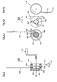
- a tensioning aid 100 is shown, which also serves as a locking means for locking the tensioning device 1.
- the tensioning aid 100 consists of a winding roller 101 about which the pull cable 151 'in FIG. 1 is wound and above the winding roll 100 leaves them again as pull 105.
- the pull cable 105 is connected to the piston 5 'in FIG. 1 connected.
- the winding roller 101 has a brake drum 103.
- In the brake drum 103 is an intake brake 102, which prevents unwinding of the drawstring or the cable 105. Turns the tensioning aid 100 in the FIG.
- the infeed brake 102 prevents unwinding in a clockwise direction, because the inlet brake 102 locks within the brake drum 103.
- counterclockwise winding allows the inlet brake 102, so that the tensioning aid 100 can wind up the tension band or the cable 105 without resistance.
- an optional torsion spring 104 which gives the clamping aid 100 so much torque that it winds the drawstring or the cable 105 against its own rigidity.
- the torsion spring 104 is not primarily intended to serve as Spannkrafterburg ceremonies, but it is possible here to install such a strong torsion spring 104, thereby tightening the clamping device 1 in FIG. 1 is relieved.
- the inlet brake 102 is lifted off the brake drum 103 with the aid of the trigger 160, so that the tensioning aid 100 by unwinding the winding roller 101, the tensioning device 1 in FIG. 1 allows.
- the intake brake this is constructed as a blind-lock, so that the inlet brake 102 by briefly actuation of the winding roll 100 releases its locking and thereby the relaxation of the clamping means 9, 9 'in FIG. 1 allows.
- the inlet brake 102 does not completely solve this, but brakes a movement of the winding roll 100, so that a relaxation of the clamping means 9, 9 'does not happen suddenly, but slowly. As a result, accidents can be avoided.
- FIG. 3 an expanded tensioning aid 200 is shown, which in addition to the previously described tensioning aid 100 another winding roller 110 on a common Has axis 90, wherein the winding roller 110 has a reversed to the clamping aid 100 or the same winding direction.
- This additional roller 110 with wrong or same sense of winding serves to receive a pull cable 111, which can be actuated by a handle 112. If the pulling cable 111 is pulled by the handle 112, then the winding roller 110 is unwound and, at the same time, the tensioning aid 100 wraps itself up and thereby shortens the path of the drawstring or of the cable 105 within the tensioning device 1 FIG. 1 , As a result, the clamping device 1 spans in FIG. 1 because the path between the clamping rings 6, 6 'shortens.
- the roller 110 and the tensioning aid 100 are connected to each other in the extended tensioning aid 200 via a planetary gear 109, so that the roller 110 during unwinding rotates faster than the tensioning aid 100 during clamping.
- a torque gain in the transmission of drawstring 111 to drawstring or cable 105 is achieved, which means a greater ease, especially for large lights with a correspondingly large clamping device 1.
- the winding roller 110 may also have a square in its axial center, in which a crank 113 can be inserted for manual actuation of the crank. As when pulling on the drawstring 111 by the handle 112 can be achieved by turning the crank 113 that the tensioning aid 100, the drawstring or the cable 105 winds and thereby the tensioning device 1 in FIG. 1 stressed.
- the planetary gear 109 can also couple the tensioning aid 100 and the winding roller 110 in such a way that the pulling path of the tension band 111 is shortened relative to the pulling path of the tension band or cable 105.
- This type of coupling is suitable for luminaires whose tensioning device 1 can be tensioned with little force.
- the drawstring 111 does not protrude so far from the tensioning aid 200 after tensioning and thus hangs down unfavorably from the lamp.
- FIG. 4 is the clamping aid 200 off FIG. 3 shown in disassembled form, with a plan view of the tensioning aid 100, the open planetary gear 109 and the winding roller 110 is given.
- the tensioning aid 100 is identical to the tensioning aid except for its seat on the common axis with the planetary gear 109 FIG. 2 .
- tensioning aid 100 is coupled to the sun gear 106 of the planetary gear 109 or meshes with a not shown internal teeth on the rear side of the tensioning aid 100 with the three planet gears 107, 107 ', 107 "of the planetary gear 109.
- the winding roller 110 engages the sun gear 106 or the planetary gears 107, 107', 107" at.
- the winding wheel 110 moves in the counterclockwise direction. If the winding roller is connected to the sun gear 106 of the planetary gear 109, then the central sun gear 106 meshes with the three planet gears 107, 107 ', 107 " Planetary gear 109. As a result, the three planetary gears mesh 107, 107 ', 107 "clockwise against the sun gear 106 and the three planetary gears 107, 107', 107" mesh against an internal toothing, not shown here, which on the rear side of the tensioning aid, not shown here 100 is arranged. As a result, the tensioning aid 100 also rotates in the clockwise direction, so that the tension band or the cable 105 is wound up.
- the torque which is applied to the tensioning aid 100 for clamping the tensioning device 1 in FIG. 1 is required, reduced when transferred to the winding roll 110.
- the winding roller 110 is not connected to the axis of the sun gear 106, but meshes with a not shown internal teeth on the back of the winding roller 110 to the three planetary gears 107, 107 ', 107 "and the clamping device 100 on the axis of the sun gear 106 of Connected to the planetary gear 109, so the torque ratio turns around, which leads to the advantages set out above.
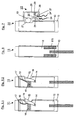
- FIG. 5 is an inventive locking assembly 11 for the telescopic rod 2 of a portable lamp FIG. 1 shown.
- the locking arrangement 11 is arranged within a telescopic linkage 2, which here consists of a telescopic rod 12 and a telescopic sleeve 13.
- a bimetallic bearing 17 On a bimetallic bearing 17, a bimetal 18 is arranged, which curves in the heated state and thus pushes against the train of the locking spring 16, the bolt 15 to the outside.
- the bolt 15 can protrude from a recess 19 in the telescopic sleeve 13 and thus prevent the expansion of the telescopic linkage 2.
- the same locking arrangement 11 is shown, but wherein the bimetal 18 in the cooled state has a different shape and thus the Bar spring 16 pulls the latch 15 in the interior of the telescopic rod 12.
- the bolt 15 thus clears the way for an expansion of the telescopic linkage 2, so that the inner telescopic rod 12 can slide within the telescopic sleeve 13.
- FIG. 6 is a further embodiment of the locking assembly 11 for the telescopic rod 2 of a portable lamp FIG. 1 shown.
- a bimetal which pushes into a latch bolt
- the brass cylinder 170 expands within the telescopic sleeve 13 and thus jammed, whereby the telescopic rod 12 can no longer slide within the telescopic sleeve 13.
- the brass cylinder 170 retracts within the telescoping sleeve 13 and clears the path for sliding the telescoping sleeve 12 within the telescoping sleeve 13.
- FIG. 7 an interruptor arrangement 20 according to the invention for a telescopic rod 2 of a portable lamp is shown.
- a recess 21 is arranged under a breaker contact 22, that a shoe 23 can connect a supply line 24 to form an electrical contact between contacts 25 and contact rod 26.
- the shoe 23 is disposed on a contact rod 26 and rotates about an axis 27 which is disposed in the breaker housing 28.
- a sliding shoe spring 29 presses the sliding block 23 in the direction of the recess 21 of the telescopic rod 12.
- the sliding block 23 is moved into the interior of the interrupter housing 28 by the displaced recess 21 and the contact between the contact rod 26 becomes and contact 25 is opened, so that the supply line 24 is electrically interrupted.
Landscapes
- Engineering & Computer Science (AREA)
- General Engineering & Computer Science (AREA)
- Non-Portable Lighting Devices Or Systems Thereof (AREA)
- Arrangement Of Elements, Cooling, Sealing, Or The Like Of Lighting Devices (AREA)
- Liquid Crystal Substances (AREA)
- Securing Globes, Refractors, Reflectors Or The Like (AREA)
- Eye Examination Apparatus (AREA)
- Telephone Set Structure (AREA)
- Fencing (AREA)
Claims (11)
- Luminaire (500) pourvue d'un abat-jour pliable présentant, au moins partiellement, une couche réfléchissante (300), au moins un moyen de tension mobile (2, 9) servant à tendre l'abat-jour pliable (300), l'abat-jour pliable (300) renfermant un moyen d'éclairage (8),
caractérisée par le fait qu'au moins un dispositif (11, 20) est prévu, qui surveille l'état tendu de l'abat-jour pliable (300) et/ou la température du moyen d'éclairage (8) et au moins un des dispositifs (11, 20), en fonction de la température du moyen d'éclairage (8), bloque le moyen de tension (2, 9) de l'abat-jour pliable (300). - Luminaire (500) selon la revendication 1, caractérisée par le fait qu'au moins un des dispositifs (11, 20) interrompt une alimentation en courant électrique du moyen d'éclairage (8) en fonction de l'état de tension du dispositif de tension (1).
- Luminaire (500) selon l'une des revendications 1 ou 2, caractérisée par le fait que le dispositif (11, 20) présente un élément (5, 5') qui bloque un élément de moyen de tension (3) des moyens de tension (2, 9) par dilatation thermique.
- Luminaire (500) selon l'une des revendications précédentes, caractérisée par le fait que le dispositif (11, 20) est constitué de deux éléments s'interpénétrant (4, 4', 5, 5') fabriqués en matériaux différents, le matériau du premier élément (4, 4') présentant un coefficient de dilatation thermique différent du second élément (5, 5').
- Luminaire (500) selon la revendication 4, caractérisée par le fait que le dispositif (11, 20) est un piston (5, 5') coulissant dans un cylindre creux en bois (4, 4'), le matériau du piston (5, 5') possédant un coefficient de dilatation thermique supérieur au matériau du cylindre creux en bois (4, 4').
- Lampe (500) selon l'une des revendications précédentes, caractérisée par le fait que le dispositif (11, 20) est un anneau coulissant sur une barre (3, 3').
- Luminaire (500) selon l'une des revendications précédentes, caractérisée par le fait qu'au moins un élément (2) des moyens de tension (9) est bloqué par un élément de verrouillage (15), l'élément de verrouillage (15) faisant saillie en raison de la dilatation thermique dans la course de tension de l'élément (2) du moyen de tension (9) libre en d'autres circonstances.
- Luminaire (500) selon la revendication 7, caractérisée par le fait que l'élément de verrouillage (15) est maintenu fixe et entrave ou bloque le déplacement du moyen de tension (2, 9).
- Luminaire (500) selon l'une des revendications 7 et 8, caractérisée par le fait que l'élément de verrouillage (15) est disposé sur l'élément de tension (2) et fait saillie à l'état chauffé dans un barillet de verrou correspondant (19).
- Luminaire (500) selon l'une des revendications précédentes, caractérisée par le fait qu'au moins un élément (21) des moyens de tension (2, 9) déclenche à l'état détendu un rupteur électrique (20).
- Luminaire (500) selon l'une des revendications 1 à 6, caractérisée par le fait qu'un dispositif auxiliaire de tension (100, 200) est prévu, qui modifie la quantité d'effort nécessaire à la tension du dispositif de tension (1), le moyen de tension (100, 200) présentant un palan (100), un câble de déviation (105) ou un engrenage (109).
Priority Applications (1)
| Application Number | Priority Date | Filing Date | Title |
|---|---|---|---|
| PL05738427T PL1728023T3 (pl) | 2004-03-26 | 2005-03-15 | Lampa przenośna |
Applications Claiming Priority (2)
| Application Number | Priority Date | Filing Date | Title |
|---|---|---|---|
| DE202004004984U DE202004004984U1 (de) | 2004-03-26 | 2004-03-26 | Transportable Leuchte |
| PCT/DE2005/000469 WO2005095845A2 (fr) | 2004-03-26 | 2005-03-15 | Lampe transportable |
Publications (2)
| Publication Number | Publication Date |
|---|---|
| EP1728023A2 EP1728023A2 (fr) | 2006-12-06 |
| EP1728023B1 true EP1728023B1 (fr) | 2009-05-20 |
Family
ID=32478554
Family Applications (1)
| Application Number | Title | Priority Date | Filing Date |
|---|---|---|---|
| EP05738427A Expired - Lifetime EP1728023B1 (fr) | 2004-03-26 | 2005-03-15 | Lampe transportable |
Country Status (9)
| Country | Link |
|---|---|
| EP (1) | EP1728023B1 (fr) |
| JP (2) | JP4451883B2 (fr) |
| CN (1) | CN1938543B (fr) |
| AT (1) | ATE431920T1 (fr) |
| AU (1) | AU2005228934B2 (fr) |
| DE (3) | DE202004004984U1 (fr) |
| NZ (1) | NZ549919A (fr) |
| PL (1) | PL1728023T3 (fr) |
| WO (1) | WO2005095845A2 (fr) |
Cited By (1)
| Publication number | Priority date | Publication date | Assignee | Title |
|---|---|---|---|---|
| US11287103B2 (en) | 2019-04-22 | 2022-03-29 | Ism Lighting, Llc. | Low wattage balloon work light |
Families Citing this family (7)
| Publication number | Priority date | Publication date | Assignee | Title |
|---|---|---|---|---|
| CN2847012Y (zh) * | 2005-08-29 | 2006-12-13 | 吴松吉 | 改良的轻气球装饰灯 |
| JP5341950B2 (ja) * | 2011-05-24 | 2013-11-13 | 株式会社モンベル | ランタンシェード |
| CN102853281A (zh) * | 2011-06-30 | 2013-01-02 | 天津工业大学 | 一种灯具 |
| DE102013002202A1 (de) * | 2013-02-07 | 2014-08-07 | Wacker Neuson Produktion GmbH & Co. KG | Transportable Leuchtvorrichtung |
| KR101655556B1 (ko) * | 2014-11-03 | 2016-09-23 | 현대자동차주식회사 | 무드등과 독서등 겸용 램프 |
| KR101812134B1 (ko) * | 2016-04-11 | 2017-12-27 | 아이투엠 주식회사 | 외형이 변형되는 주름형상의 갓을 갖는 조명기구 |
| CN110131612B (zh) * | 2019-03-25 | 2021-06-04 | 山东光明园迪儿童家具科技有限公司 | 一种防尘台灯 |
Family Cites Families (7)
| Publication number | Priority date | Publication date | Assignee | Title |
|---|---|---|---|---|
| US3870062A (en) * | 1974-04-22 | 1975-03-11 | Richard Larry Medlin | Illuminated pavilion umbrella |
| FR2678811A1 (fr) * | 1991-07-08 | 1993-01-15 | Perrier Noel | Parasol solaire multi-fonctions. |
| CN2152142Y (zh) * | 1993-04-02 | 1994-01-05 | 周贵新 | 可折叠的闪烁灯壳体 |
| US6527418B1 (en) * | 1997-05-27 | 2003-03-04 | Scherba Industries, Inc. | Light cooler |
| DE29910204U1 (de) * | 1999-06-11 | 2000-03-23 | Nölle, Jürgen, Dipl.-Ing., 47495 Rheinberg | Federschirmleuchte |
| JP2001067911A (ja) * | 1999-08-25 | 2001-03-16 | Shigeo Tamaoki | 装飾用照明具 |
| CN2492942Y (zh) * | 2001-08-03 | 2002-05-22 | 黄贵山 | 高空灯泡装卸器 |
-
2004
- 2004-03-26 DE DE202004004984U patent/DE202004004984U1/de not_active Expired - Lifetime
-
2005
- 2005-03-15 DE DE502005007319T patent/DE502005007319D1/de not_active Expired - Lifetime
- 2005-03-15 WO PCT/DE2005/000469 patent/WO2005095845A2/fr not_active Ceased
- 2005-03-15 PL PL05738427T patent/PL1728023T3/pl unknown
- 2005-03-15 EP EP05738427A patent/EP1728023B1/fr not_active Expired - Lifetime
- 2005-03-15 CN CN2005800098174A patent/CN1938543B/zh not_active Expired - Fee Related
- 2005-03-15 AT AT05738427T patent/ATE431920T1/de active
- 2005-03-15 JP JP2006551715A patent/JP4451883B2/ja not_active Expired - Fee Related
- 2005-03-15 AU AU2005228934A patent/AU2005228934B2/en not_active Ceased
- 2005-03-15 NZ NZ549919A patent/NZ549919A/en not_active IP Right Cessation
- 2005-03-15 DE DE112005001288T patent/DE112005001288A5/de not_active Withdrawn
-
2009
- 2009-09-11 JP JP2009211119A patent/JP4644297B2/ja not_active Expired - Fee Related
Cited By (1)
| Publication number | Priority date | Publication date | Assignee | Title |
|---|---|---|---|---|
| US11287103B2 (en) | 2019-04-22 | 2022-03-29 | Ism Lighting, Llc. | Low wattage balloon work light |
Also Published As
| Publication number | Publication date |
|---|---|
| DE112005001288A5 (de) | 2007-05-24 |
| AU2005228934A1 (en) | 2005-10-13 |
| ATE431920T1 (de) | 2009-06-15 |
| JP2007522614A (ja) | 2007-08-09 |
| PL1728023T3 (pl) | 2009-10-30 |
| WO2005095845A3 (fr) | 2006-05-11 |
| JP4451883B2 (ja) | 2010-04-14 |
| JP2010015999A (ja) | 2010-01-21 |
| CN1938543B (zh) | 2012-04-18 |
| DE502005007319D1 (de) | 2009-07-02 |
| JP4644297B2 (ja) | 2011-03-02 |
| NZ549919A (en) | 2009-10-30 |
| AU2005228934B2 (en) | 2009-02-26 |
| EP1728023A2 (fr) | 2006-12-06 |
| CN1938543A (zh) | 2007-03-28 |
| DE202004004984U1 (de) | 2004-06-03 |
| WO2005095845A2 (fr) | 2005-10-13 |
Similar Documents
| Publication | Publication Date | Title |
|---|---|---|
| EP1059483B1 (fr) | Lampe portative | |
| DE102011052394B4 (de) | Falt-Reflektor | |
| EP3619457B1 (fr) | Trépied | |
| EP1279350B1 (fr) | Manche de parasol et parasol comprenant un tel manche | |
| EP1728023B1 (fr) | Lampe transportable | |
| EP1182067A2 (fr) | Store à enrouleur pour fenêtre arrière | |
| JP2001081922A (ja) | モータ操作の幌(オーニング) | |
| DE20112948U1 (de) | Sichtschutzvorrichtung für eine Kraftfahrzeugscheibe | |
| DE202008004868U1 (de) | Schaltantrieb für einen Leistungstrennschalter | |
| EP0282851B1 (fr) | Barrière de parking rabattable | |
| CH594279A5 (en) | Toggle drive unit for medium voltage switch - has symmetrical double spring which reduces bearing load and gives compact construction | |
| EP2443956A2 (fr) | Parasol | |
| DE102008045312A1 (de) | Spannvorrichtung | |
| EP1102908B1 (fr) | Arret de porte | |
| EP0438145B1 (fr) | Bâche et dispositif pour l'enrouler | |
| AT5643U1 (de) | Federwelle | |
| EP4595804B1 (fr) | Mécanisme d'écartement pour dispositif pouvant être tendu et dispositif pouvant être tendu | |
| WO2007124724A1 (fr) | Élément d'éclairage | |
| DE102009036213B4 (de) | Sonnenschirmgetriebeeinheit und Sonnenschirm | |
| EP4260310B1 (fr) | Support publicitaire | |
| DE202016002322U1 (de) | Kurbel, Wickelmechanismus mit einer solchen Kurbel und Behälter mit einer Planenabdeckvorrichtung, die einen solchen Wickelmechanismus mit Kurbel umfasst | |
| DE69723064T2 (de) | Verriegelungsstange | |
| DE102009007962A1 (de) | Gebäudeöffnungs-Verschattungsvorrichtung mit ausstellbaren Führungsschienen | |
| DE102011109665B4 (de) | Schließvorrichtung | |
| DE2641885A1 (de) | Mechanischer antrieb fuer elektrische leistungsschalter |
Legal Events
| Date | Code | Title | Description |
|---|---|---|---|
| PUAI | Public reference made under article 153(3) epc to a published international application that has entered the european phase |
Free format text: ORIGINAL CODE: 0009012 |
|
| AK | Designated contracting states |
Kind code of ref document: A2 Designated state(s): AT BE BG CH CY CZ DE DK EE ES FI FR GB GR HU IE IS IT LI LT LU MC NL PL PT RO SE SI SK TR |
|
| AX | Request for extension of the european patent |
Extension state: AL BA HR LV MK YU |
|
| 17P | Request for examination filed |
Effective date: 20061024 |
|
| DAX | Request for extension of the european patent (deleted) | ||
| 17Q | First examination report despatched |
Effective date: 20070913 |
|
| R17C | First examination report despatched (corrected) |
Effective date: 20080411 |
|
| GRAP | Despatch of communication of intention to grant a patent |
Free format text: ORIGINAL CODE: EPIDOSNIGR1 |
|
| GRAS | Grant fee paid |
Free format text: ORIGINAL CODE: EPIDOSNIGR3 |
|
| GRAA | (expected) grant |
Free format text: ORIGINAL CODE: 0009210 |
|
| AK | Designated contracting states |
Kind code of ref document: B1 Designated state(s): AT BE BG CH CY CZ DE DK EE ES FI FR GB GR HU IE IS IT LI LT LU MC NL PL PT RO SE SI SK TR |
|
| REG | Reference to a national code |
Ref country code: GB Ref legal event code: FG4D Free format text: NOT ENGLISH |
|
| REG | Reference to a national code |
Ref country code: CH Ref legal event code: EP |
|
| REG | Reference to a national code |
Ref country code: IE Ref legal event code: FG4D Free format text: LANGUAGE OF EP DOCUMENT: GERMAN |
|
| REF | Corresponds to: |
Ref document number: 502005007319 Country of ref document: DE Date of ref document: 20090702 Kind code of ref document: P |
|
| REG | Reference to a national code |
Ref country code: RO Ref legal event code: EPE |
|
| REG | Reference to a national code |
Ref country code: EE Ref legal event code: FG4A Ref document number: E003540 Country of ref document: EE Effective date: 20090818 |
|
| PG25 | Lapsed in a contracting state [announced via postgrant information from national office to epo] |
Ref country code: PT Free format text: LAPSE BECAUSE OF FAILURE TO SUBMIT A TRANSLATION OF THE DESCRIPTION OR TO PAY THE FEE WITHIN THE PRESCRIBED TIME-LIMIT Effective date: 20090920 Ref country code: LT Free format text: LAPSE BECAUSE OF FAILURE TO SUBMIT A TRANSLATION OF THE DESCRIPTION OR TO PAY THE FEE WITHIN THE PRESCRIBED TIME-LIMIT Effective date: 20090520 Ref country code: FI Free format text: LAPSE BECAUSE OF FAILURE TO SUBMIT A TRANSLATION OF THE DESCRIPTION OR TO PAY THE FEE WITHIN THE PRESCRIBED TIME-LIMIT Effective date: 20090520 Ref country code: ES Free format text: LAPSE BECAUSE OF FAILURE TO SUBMIT A TRANSLATION OF THE DESCRIPTION OR TO PAY THE FEE WITHIN THE PRESCRIBED TIME-LIMIT Effective date: 20090831 |
|
| REG | Reference to a national code |
Ref country code: PL Ref legal event code: T3 |
|
| PG25 | Lapsed in a contracting state [announced via postgrant information from national office to epo] |
Ref country code: IS Free format text: LAPSE BECAUSE OF FAILURE TO SUBMIT A TRANSLATION OF THE DESCRIPTION OR TO PAY THE FEE WITHIN THE PRESCRIBED TIME-LIMIT Effective date: 20090920 Ref country code: SI Free format text: LAPSE BECAUSE OF FAILURE TO SUBMIT A TRANSLATION OF THE DESCRIPTION OR TO PAY THE FEE WITHIN THE PRESCRIBED TIME-LIMIT Effective date: 20090520 Ref country code: SE Free format text: LAPSE BECAUSE OF FAILURE TO SUBMIT A TRANSLATION OF THE DESCRIPTION OR TO PAY THE FEE WITHIN THE PRESCRIBED TIME-LIMIT Effective date: 20090820 |
|
| REG | Reference to a national code |
Ref country code: IE Ref legal event code: FD4D |
|
| PG25 | Lapsed in a contracting state [announced via postgrant information from national office to epo] |
Ref country code: DK Free format text: LAPSE BECAUSE OF FAILURE TO SUBMIT A TRANSLATION OF THE DESCRIPTION OR TO PAY THE FEE WITHIN THE PRESCRIBED TIME-LIMIT Effective date: 20090520 Ref country code: IE Free format text: LAPSE BECAUSE OF FAILURE TO SUBMIT A TRANSLATION OF THE DESCRIPTION OR TO PAY THE FEE WITHIN THE PRESCRIBED TIME-LIMIT Effective date: 20090520 |
|
| REG | Reference to a national code |
Ref country code: HU Ref legal event code: AG4A Ref document number: E006576 Country of ref document: HU |
|
| PLBE | No opposition filed within time limit |
Free format text: ORIGINAL CODE: 0009261 |
|
| STAA | Information on the status of an ep patent application or granted ep patent |
Free format text: STATUS: NO OPPOSITION FILED WITHIN TIME LIMIT |
|
| 26N | No opposition filed |
Effective date: 20100223 |
|
| PG25 | Lapsed in a contracting state [announced via postgrant information from national office to epo] |
Ref country code: MC Free format text: LAPSE BECAUSE OF NON-PAYMENT OF DUE FEES Effective date: 20100331 Ref country code: GR Free format text: LAPSE BECAUSE OF FAILURE TO SUBMIT A TRANSLATION OF THE DESCRIPTION OR TO PAY THE FEE WITHIN THE PRESCRIBED TIME-LIMIT Effective date: 20090821 |
|
| PG25 | Lapsed in a contracting state [announced via postgrant information from national office to epo] |
Ref country code: CY Free format text: LAPSE BECAUSE OF FAILURE TO SUBMIT A TRANSLATION OF THE DESCRIPTION OR TO PAY THE FEE WITHIN THE PRESCRIBED TIME-LIMIT Effective date: 20090520 |
|
| REG | Reference to a national code |
Ref country code: FR Ref legal event code: PLFP Year of fee payment: 12 |
|
| REG | Reference to a national code |
Ref country code: FR Ref legal event code: PLFP Year of fee payment: 13 |
|
| REG | Reference to a national code |
Ref country code: FR Ref legal event code: PLFP Year of fee payment: 14 |
|
| PGFP | Annual fee paid to national office [announced via postgrant information from national office to epo] |
Ref country code: HU Payment date: 20220308 Year of fee payment: 18 Ref country code: GB Payment date: 20220324 Year of fee payment: 18 Ref country code: CH Payment date: 20220324 Year of fee payment: 18 Ref country code: BG Payment date: 20220318 Year of fee payment: 18 Ref country code: AT Payment date: 20220318 Year of fee payment: 18 |
|
| PGFP | Annual fee paid to national office [announced via postgrant information from national office to epo] |
Ref country code: TR Payment date: 20220304 Year of fee payment: 18 Ref country code: SK Payment date: 20220303 Year of fee payment: 18 Ref country code: RO Payment date: 20220303 Year of fee payment: 18 Ref country code: PL Payment date: 20220225 Year of fee payment: 18 Ref country code: NL Payment date: 20220322 Year of fee payment: 18 Ref country code: LU Payment date: 20220322 Year of fee payment: 18 Ref country code: FR Payment date: 20220322 Year of fee payment: 18 Ref country code: EE Payment date: 20220321 Year of fee payment: 18 Ref country code: CZ Payment date: 20220303 Year of fee payment: 18 Ref country code: BE Payment date: 20220322 Year of fee payment: 18 |
|
| PGFP | Annual fee paid to national office [announced via postgrant information from national office to epo] |
Ref country code: IT Payment date: 20220331 Year of fee payment: 18 Ref country code: DE Payment date: 20220530 Year of fee payment: 18 |
|
| REG | Reference to a national code |
Ref country code: DE Ref legal event code: R119 Ref document number: 502005007319 Country of ref document: DE |
|
| REG | Reference to a national code |
Ref country code: EE Ref legal event code: MM4A Ref document number: E003540 Country of ref document: EE Effective date: 20230331 |
|
| PG25 | Lapsed in a contracting state [announced via postgrant information from national office to epo] |
Ref country code: RO Free format text: LAPSE BECAUSE OF NON-PAYMENT OF DUE FEES Effective date: 20230315 Ref country code: CZ Free format text: LAPSE BECAUSE OF NON-PAYMENT OF DUE FEES Effective date: 20230315 |
|
| REG | Reference to a national code |
Ref country code: CH Ref legal event code: PL |
|
| REG | Reference to a national code |
Ref country code: SK Ref legal event code: MM4A Ref document number: E 5884 Country of ref document: SK Effective date: 20230315 Ref country code: NL Ref legal event code: MM Effective date: 20230401 |
|
| REG | Reference to a national code |
Ref country code: AT Ref legal event code: MM01 Ref document number: 431920 Country of ref document: AT Kind code of ref document: T Effective date: 20230315 |
|
| GBPC | Gb: european patent ceased through non-payment of renewal fee |
Effective date: 20230315 |
|
| REG | Reference to a national code |
Ref country code: BE Ref legal event code: MM Effective date: 20230331 |
|
| PG25 | Lapsed in a contracting state [announced via postgrant information from national office to epo] |
Ref country code: NL Free format text: LAPSE BECAUSE OF NON-PAYMENT OF DUE FEES Effective date: 20230401 Ref country code: LU Free format text: LAPSE BECAUSE OF NON-PAYMENT OF DUE FEES Effective date: 20230315 |
|
| PG25 | Lapsed in a contracting state [announced via postgrant information from national office to epo] |
Ref country code: SK Free format text: LAPSE BECAUSE OF NON-PAYMENT OF DUE FEES Effective date: 20230315 |
|
| PG25 | Lapsed in a contracting state [announced via postgrant information from national office to epo] |
Ref country code: GB Free format text: LAPSE BECAUSE OF NON-PAYMENT OF DUE FEES Effective date: 20230315 |
|
| PG25 | Lapsed in a contracting state [announced via postgrant information from national office to epo] |
Ref country code: SK Free format text: LAPSE BECAUSE OF NON-PAYMENT OF DUE FEES Effective date: 20230315 Ref country code: LI Free format text: LAPSE BECAUSE OF NON-PAYMENT OF DUE FEES Effective date: 20230331 Ref country code: HU Free format text: LAPSE BECAUSE OF NON-PAYMENT OF DUE FEES Effective date: 20230316 Ref country code: GB Free format text: LAPSE BECAUSE OF NON-PAYMENT OF DUE FEES Effective date: 20230315 Ref country code: FR Free format text: LAPSE BECAUSE OF NON-PAYMENT OF DUE FEES Effective date: 20230331 Ref country code: EE Free format text: LAPSE BECAUSE OF NON-PAYMENT OF DUE FEES Effective date: 20230331 Ref country code: DE Free format text: LAPSE BECAUSE OF NON-PAYMENT OF DUE FEES Effective date: 20231003 Ref country code: CH Free format text: LAPSE BECAUSE OF NON-PAYMENT OF DUE FEES Effective date: 20230331 Ref country code: AT Free format text: LAPSE BECAUSE OF NON-PAYMENT OF DUE FEES Effective date: 20230315 |
|
| PG25 | Lapsed in a contracting state [announced via postgrant information from national office to epo] |
Ref country code: BE Free format text: LAPSE BECAUSE OF NON-PAYMENT OF DUE FEES Effective date: 20230331 |
|
| PG25 | Lapsed in a contracting state [announced via postgrant information from national office to epo] |
Ref country code: IT Free format text: LAPSE BECAUSE OF NON-PAYMENT OF DUE FEES Effective date: 20230315 |
|
| PG25 | Lapsed in a contracting state [announced via postgrant information from national office to epo] |
Ref country code: PL Free format text: LAPSE BECAUSE OF NON-PAYMENT OF DUE FEES Effective date: 20230315 |
|
| PG25 | Lapsed in a contracting state [announced via postgrant information from national office to epo] |
Ref country code: PL Free format text: LAPSE BECAUSE OF NON-PAYMENT OF DUE FEES Effective date: 20230315 |
|
| PG25 | Lapsed in a contracting state [announced via postgrant information from national office to epo] |
Ref country code: BG Free format text: LAPSE BECAUSE OF NON-PAYMENT OF DUE FEES Effective date: 20230315 |
|
| PG25 | Lapsed in a contracting state [announced via postgrant information from national office to epo] |
Ref country code: BG Free format text: LAPSE BECAUSE OF NON-PAYMENT OF DUE FEES Effective date: 20230315 |