EP1728546A2 - Tauchmembrankassette und deren Herstellungsverfahren - Google Patents
Tauchmembrankassette und deren Herstellungsverfahren Download PDFInfo
- Publication number
- EP1728546A2 EP1728546A2 EP06008357A EP06008357A EP1728546A2 EP 1728546 A2 EP1728546 A2 EP 1728546A2 EP 06008357 A EP06008357 A EP 06008357A EP 06008357 A EP06008357 A EP 06008357A EP 1728546 A2 EP1728546 A2 EP 1728546A2
- Authority
- EP
- European Patent Office
- Prior art keywords
- membrane
- supporting plate
- welding
- fixing portion
- welding allowance
- Prior art date
- Legal status (The legal status is an assumption and is not a legal conclusion. Google has not performed a legal analysis and makes no representation as to the accuracy of the status listed.)
- Ceased
Links
Images


Classifications
-
- B—PERFORMING OPERATIONS; TRANSPORTING
- B29—WORKING OF PLASTICS; WORKING OF SUBSTANCES IN A PLASTIC STATE IN GENERAL
- B29C—SHAPING OR JOINING OF PLASTICS; SHAPING OF MATERIAL IN A PLASTIC STATE, NOT OTHERWISE PROVIDED FOR; AFTER-TREATMENT OF THE SHAPED PRODUCTS, e.g. REPAIRING
- B29C65/00—Joining or sealing of preformed parts, e.g. welding of plastics materials; Apparatus therefor
- B29C65/02—Joining or sealing of preformed parts, e.g. welding of plastics materials; Apparatus therefor by heating, with or without pressure
- B29C65/08—Joining or sealing of preformed parts, e.g. welding of plastics materials; Apparatus therefor by heating, with or without pressure using ultrasonic vibrations
-
- B—PERFORMING OPERATIONS; TRANSPORTING
- B01—PHYSICAL OR CHEMICAL PROCESSES OR APPARATUS IN GENERAL
- B01D—SEPARATION
- B01D61/00—Processes of separation using semi-permeable membranes, e.g. dialysis, osmosis or ultrafiltration; Apparatus, accessories or auxiliary operations specially adapted therefor
- B01D61/14—Ultrafiltration; Microfiltration
- B01D61/18—Apparatus therefor
-
- B—PERFORMING OPERATIONS; TRANSPORTING
- B01—PHYSICAL OR CHEMICAL PROCESSES OR APPARATUS IN GENERAL
- B01D—SEPARATION
- B01D63/00—Apparatus in general for separation processes using semi-permeable membranes
- B01D63/08—Flat membrane modules
- B01D63/081—Manufacturing thereof
-
- B—PERFORMING OPERATIONS; TRANSPORTING
- B01—PHYSICAL OR CHEMICAL PROCESSES OR APPARATUS IN GENERAL
- B01D—SEPARATION
- B01D63/00—Apparatus in general for separation processes using semi-permeable membranes
- B01D63/08—Flat membrane modules
- B01D63/082—Flat membrane modules comprising a stack of flat membranes
- B01D63/0821—Membrane plate arrangements for submerged operation
-
- B—PERFORMING OPERATIONS; TRANSPORTING
- B01—PHYSICAL OR CHEMICAL PROCESSES OR APPARATUS IN GENERAL
- B01D—SEPARATION
- B01D65/00—Accessories or auxiliary operations, in general, for separation processes or apparatus using semi-permeable membranes
- B01D65/08—Prevention of membrane fouling or of concentration polarisation
-
- B—PERFORMING OPERATIONS; TRANSPORTING
- B29—WORKING OF PLASTICS; WORKING OF SUBSTANCES IN A PLASTIC STATE IN GENERAL
- B29C—SHAPING OR JOINING OF PLASTICS; SHAPING OF MATERIAL IN A PLASTIC STATE, NOT OTHERWISE PROVIDED FOR; AFTER-TREATMENT OF THE SHAPED PRODUCTS, e.g. REPAIRING
- B29C65/00—Joining or sealing of preformed parts, e.g. welding of plastics materials; Apparatus therefor
- B29C65/02—Joining or sealing of preformed parts, e.g. welding of plastics materials; Apparatus therefor by heating, with or without pressure
- B29C65/08—Joining or sealing of preformed parts, e.g. welding of plastics materials; Apparatus therefor by heating, with or without pressure using ultrasonic vibrations
- B29C65/083—Joining or sealing of preformed parts, e.g. welding of plastics materials; Apparatus therefor by heating, with or without pressure using ultrasonic vibrations using a rotary sonotrode or a rotary anvil
- B29C65/085—Joining or sealing of preformed parts, e.g. welding of plastics materials; Apparatus therefor by heating, with or without pressure using ultrasonic vibrations using a rotary sonotrode or a rotary anvil using a rotary sonotrode
-
- B—PERFORMING OPERATIONS; TRANSPORTING
- B29—WORKING OF PLASTICS; WORKING OF SUBSTANCES IN A PLASTIC STATE IN GENERAL
- B29C—SHAPING OR JOINING OF PLASTICS; SHAPING OF MATERIAL IN A PLASTIC STATE, NOT OTHERWISE PROVIDED FOR; AFTER-TREATMENT OF THE SHAPED PRODUCTS, e.g. REPAIRING
- B29C66/00—General aspects of processes or apparatus for joining preformed parts
- B29C66/01—General aspects dealing with the joint area or with the area to be joined
- B29C66/05—Particular design of joint configurations
- B29C66/10—Particular design of joint configurations particular design of the joint cross-sections
- B29C66/11—Joint cross-sections comprising a single joint-segment, i.e. one of the parts to be joined comprising a single joint-segment in the joint cross-section
- B29C66/112—Single lapped joints
- B29C66/1122—Single lap to lap joints, i.e. overlap joints
-
- B—PERFORMING OPERATIONS; TRANSPORTING
- B29—WORKING OF PLASTICS; WORKING OF SUBSTANCES IN A PLASTIC STATE IN GENERAL
- B29C—SHAPING OR JOINING OF PLASTICS; SHAPING OF MATERIAL IN A PLASTIC STATE, NOT OTHERWISE PROVIDED FOR; AFTER-TREATMENT OF THE SHAPED PRODUCTS, e.g. REPAIRING
- B29C66/00—General aspects of processes or apparatus for joining preformed parts
- B29C66/01—General aspects dealing with the joint area or with the area to be joined
- B29C66/05—Particular design of joint configurations
- B29C66/20—Particular design of joint configurations particular design of the joint lines, e.g. of the weld lines
- B29C66/23—Particular design of joint configurations particular design of the joint lines, e.g. of the weld lines said joint lines being multiple and parallel or being in the form of tessellations
- B29C66/232—Particular design of joint configurations particular design of the joint lines, e.g. of the weld lines said joint lines being multiple and parallel or being in the form of tessellations said joint lines being multiple and parallel, i.e. the joint being formed by several parallel joint lines
-
- B—PERFORMING OPERATIONS; TRANSPORTING
- B29—WORKING OF PLASTICS; WORKING OF SUBSTANCES IN A PLASTIC STATE IN GENERAL
- B29C—SHAPING OR JOINING OF PLASTICS; SHAPING OF MATERIAL IN A PLASTIC STATE, NOT OTHERWISE PROVIDED FOR; AFTER-TREATMENT OF THE SHAPED PRODUCTS, e.g. REPAIRING
- B29C66/00—General aspects of processes or apparatus for joining preformed parts
- B29C66/01—General aspects dealing with the joint area or with the area to be joined
- B29C66/05—Particular design of joint configurations
- B29C66/20—Particular design of joint configurations particular design of the joint lines, e.g. of the weld lines
- B29C66/23—Particular design of joint configurations particular design of the joint lines, e.g. of the weld lines said joint lines being multiple and parallel or being in the form of tessellations
- B29C66/234—Particular design of joint configurations particular design of the joint lines, e.g. of the weld lines said joint lines being multiple and parallel or being in the form of tessellations said joint lines being in the form of tessellations
-
- B—PERFORMING OPERATIONS; TRANSPORTING
- B29—WORKING OF PLASTICS; WORKING OF SUBSTANCES IN A PLASTIC STATE IN GENERAL
- B29C—SHAPING OR JOINING OF PLASTICS; SHAPING OF MATERIAL IN A PLASTIC STATE, NOT OTHERWISE PROVIDED FOR; AFTER-TREATMENT OF THE SHAPED PRODUCTS, e.g. REPAIRING
- B29C66/00—General aspects of processes or apparatus for joining preformed parts
- B29C66/01—General aspects dealing with the joint area or with the area to be joined
- B29C66/05—Particular design of joint configurations
- B29C66/302—Particular design of joint configurations the area to be joined comprising melt initiators
- B29C66/3022—Particular design of joint configurations the area to be joined comprising melt initiators said melt initiators being integral with at least one of the parts to be joined
- B29C66/30223—Particular design of joint configurations the area to be joined comprising melt initiators said melt initiators being integral with at least one of the parts to be joined said melt initiators being rib-like
-
- B—PERFORMING OPERATIONS; TRANSPORTING
- B29—WORKING OF PLASTICS; WORKING OF SUBSTANCES IN A PLASTIC STATE IN GENERAL
- B29C—SHAPING OR JOINING OF PLASTICS; SHAPING OF MATERIAL IN A PLASTIC STATE, NOT OTHERWISE PROVIDED FOR; AFTER-TREATMENT OF THE SHAPED PRODUCTS, e.g. REPAIRING
- B29C66/00—General aspects of processes or apparatus for joining preformed parts
- B29C66/40—General aspects of joining substantially flat articles, e.g. plates, sheets or web-like materials; Making flat seams in tubular or hollow articles; Joining single elements to substantially flat surfaces
- B29C66/41—Joining substantially flat articles ; Making flat seams in tubular or hollow articles
- B29C66/43—Joining a relatively small portion of the surface of said articles
-
- B—PERFORMING OPERATIONS; TRANSPORTING
- B29—WORKING OF PLASTICS; WORKING OF SUBSTANCES IN A PLASTIC STATE IN GENERAL
- B29C—SHAPING OR JOINING OF PLASTICS; SHAPING OF MATERIAL IN A PLASTIC STATE, NOT OTHERWISE PROVIDED FOR; AFTER-TREATMENT OF THE SHAPED PRODUCTS, e.g. REPAIRING
- B29C66/00—General aspects of processes or apparatus for joining preformed parts
- B29C66/70—General aspects of processes or apparatus for joining preformed parts characterised by the composition, physical properties or the structure of the material of the parts to be joined; Joining with non-plastics material
- B29C66/72—General aspects of processes or apparatus for joining preformed parts characterised by the composition, physical properties or the structure of the material of the parts to be joined; Joining with non-plastics material characterised by the structure of the material of the parts to be joined
- B29C66/729—Textile or other fibrous material made from plastics
- B29C66/7294—Non woven mats, e.g. felt
- B29C66/72941—Non woven mats, e.g. felt coated
-
- B—PERFORMING OPERATIONS; TRANSPORTING
- B29—WORKING OF PLASTICS; WORKING OF SUBSTANCES IN A PLASTIC STATE IN GENERAL
- B29C—SHAPING OR JOINING OF PLASTICS; SHAPING OF MATERIAL IN A PLASTIC STATE, NOT OTHERWISE PROVIDED FOR; AFTER-TREATMENT OF THE SHAPED PRODUCTS, e.g. REPAIRING
- B29C66/00—General aspects of processes or apparatus for joining preformed parts
- B29C66/70—General aspects of processes or apparatus for joining preformed parts characterised by the composition, physical properties or the structure of the material of the parts to be joined; Joining with non-plastics material
- B29C66/73—General aspects of processes or apparatus for joining preformed parts characterised by the composition, physical properties or the structure of the material of the parts to be joined; Joining with non-plastics material characterised by the intensive physical properties of the material of the parts to be joined, by the optical properties of the material of the parts to be joined, by the extensive physical properties of the parts to be joined, by the state of the material of the parts to be joined or by the material of the parts to be joined being a thermoplastic or a thermoset
- B29C66/739—General aspects of processes or apparatus for joining preformed parts characterised by the composition, physical properties or the structure of the material of the parts to be joined; Joining with non-plastics material characterised by the intensive physical properties of the material of the parts to be joined, by the optical properties of the material of the parts to be joined, by the extensive physical properties of the parts to be joined, by the state of the material of the parts to be joined or by the material of the parts to be joined being a thermoplastic or a thermoset characterised by the material of the parts to be joined being a thermoplastic or a thermoset
- B29C66/7392—General aspects of processes or apparatus for joining preformed parts characterised by the composition, physical properties or the structure of the material of the parts to be joined; Joining with non-plastics material characterised by the intensive physical properties of the material of the parts to be joined, by the optical properties of the material of the parts to be joined, by the extensive physical properties of the parts to be joined, by the state of the material of the parts to be joined or by the material of the parts to be joined being a thermoplastic or a thermoset characterised by the material of the parts to be joined being a thermoplastic or a thermoset characterised by the material of at least one of the parts being a thermoplastic
-
- B—PERFORMING OPERATIONS; TRANSPORTING
- B29—WORKING OF PLASTICS; WORKING OF SUBSTANCES IN A PLASTIC STATE IN GENERAL
- B29C—SHAPING OR JOINING OF PLASTICS; SHAPING OF MATERIAL IN A PLASTIC STATE, NOT OTHERWISE PROVIDED FOR; AFTER-TREATMENT OF THE SHAPED PRODUCTS, e.g. REPAIRING
- B29C66/00—General aspects of processes or apparatus for joining preformed parts
- B29C66/80—General aspects of machine operations or constructions and parts thereof
- B29C66/81—General aspects of the pressing elements, i.e. the elements applying pressure on the parts to be joined in the area to be joined, e.g. the welding jaws or clamps
- B29C66/814—General aspects of the pressing elements, i.e. the elements applying pressure on the parts to be joined in the area to be joined, e.g. the welding jaws or clamps characterised by the design of the pressing elements, e.g. of the welding jaws or clamps
- B29C66/8141—General aspects of the pressing elements, i.e. the elements applying pressure on the parts to be joined in the area to be joined, e.g. the welding jaws or clamps characterised by the design of the pressing elements, e.g. of the welding jaws or clamps characterised by the surface geometry of the part of the pressing elements, e.g. welding jaws or clamps, coming into contact with the parts to be joined
- B29C66/81411—General aspects of the pressing elements, i.e. the elements applying pressure on the parts to be joined in the area to be joined, e.g. the welding jaws or clamps characterised by the design of the pressing elements, e.g. of the welding jaws or clamps characterised by the surface geometry of the part of the pressing elements, e.g. welding jaws or clamps, coming into contact with the parts to be joined characterised by its cross-section, e.g. transversal or longitudinal, being non-flat
- B29C66/81425—General aspects of the pressing elements, i.e. the elements applying pressure on the parts to be joined in the area to be joined, e.g. the welding jaws or clamps characterised by the design of the pressing elements, e.g. of the welding jaws or clamps characterised by the surface geometry of the part of the pressing elements, e.g. welding jaws or clamps, coming into contact with the parts to be joined characterised by its cross-section, e.g. transversal or longitudinal, being non-flat being stepped, e.g. comprising a shoulder
-
- B—PERFORMING OPERATIONS; TRANSPORTING
- B29—WORKING OF PLASTICS; WORKING OF SUBSTANCES IN A PLASTIC STATE IN GENERAL
- B29C—SHAPING OR JOINING OF PLASTICS; SHAPING OF MATERIAL IN A PLASTIC STATE, NOT OTHERWISE PROVIDED FOR; AFTER-TREATMENT OF THE SHAPED PRODUCTS, e.g. REPAIRING
- B29C66/00—General aspects of processes or apparatus for joining preformed parts
- B29C66/80—General aspects of machine operations or constructions and parts thereof
- B29C66/81—General aspects of the pressing elements, i.e. the elements applying pressure on the parts to be joined in the area to be joined, e.g. the welding jaws or clamps
- B29C66/814—General aspects of the pressing elements, i.e. the elements applying pressure on the parts to be joined in the area to be joined, e.g. the welding jaws or clamps characterised by the design of the pressing elements, e.g. of the welding jaws or clamps
- B29C66/8141—General aspects of the pressing elements, i.e. the elements applying pressure on the parts to be joined in the area to be joined, e.g. the welding jaws or clamps characterised by the design of the pressing elements, e.g. of the welding jaws or clamps characterised by the surface geometry of the part of the pressing elements, e.g. welding jaws or clamps, coming into contact with the parts to be joined
- B29C66/81433—General aspects of the pressing elements, i.e. the elements applying pressure on the parts to be joined in the area to be joined, e.g. the welding jaws or clamps characterised by the design of the pressing elements, e.g. of the welding jaws or clamps characterised by the surface geometry of the part of the pressing elements, e.g. welding jaws or clamps, coming into contact with the parts to be joined being toothed, i.e. comprising several teeth or pins, or being patterned
-
- B—PERFORMING OPERATIONS; TRANSPORTING
- B29—WORKING OF PLASTICS; WORKING OF SUBSTANCES IN A PLASTIC STATE IN GENERAL
- B29C—SHAPING OR JOINING OF PLASTICS; SHAPING OF MATERIAL IN A PLASTIC STATE, NOT OTHERWISE PROVIDED FOR; AFTER-TREATMENT OF THE SHAPED PRODUCTS, e.g. REPAIRING
- B29C66/00—General aspects of processes or apparatus for joining preformed parts
- B29C66/80—General aspects of machine operations or constructions and parts thereof
- B29C66/83—General aspects of machine operations or constructions and parts thereof characterised by the movement of the joining or pressing tools
- B29C66/832—Reciprocating joining or pressing tools
- B29C66/8322—Joining or pressing tools reciprocating along one axis
-
- B—PERFORMING OPERATIONS; TRANSPORTING
- B29—WORKING OF PLASTICS; WORKING OF SUBSTANCES IN A PLASTIC STATE IN GENERAL
- B29C—SHAPING OR JOINING OF PLASTICS; SHAPING OF MATERIAL IN A PLASTIC STATE, NOT OTHERWISE PROVIDED FOR; AFTER-TREATMENT OF THE SHAPED PRODUCTS, e.g. REPAIRING
- B29C66/00—General aspects of processes or apparatus for joining preformed parts
- B29C66/80—General aspects of machine operations or constructions and parts thereof
- B29C66/83—General aspects of machine operations or constructions and parts thereof characterised by the movement of the joining or pressing tools
- B29C66/836—Moving relative to and tangentially to the parts to be joined, e.g. transversely to the displacement of the parts to be joined, e.g. using a X-Y table
- B29C66/8362—Rollers, cylinders or drums moving relative to and tangentially to the parts to be joined
-
- B—PERFORMING OPERATIONS; TRANSPORTING
- B01—PHYSICAL OR CHEMICAL PROCESSES OR APPARATUS IN GENERAL
- B01D—SEPARATION
- B01D2321/00—Details relating to membrane cleaning, regeneration, sterilization or to the prevention of fouling
- B01D2321/18—Use of gases
- B01D2321/185—Aeration
-
- B—PERFORMING OPERATIONS; TRANSPORTING
- B29—WORKING OF PLASTICS; WORKING OF SUBSTANCES IN A PLASTIC STATE IN GENERAL
- B29C—SHAPING OR JOINING OF PLASTICS; SHAPING OF MATERIAL IN A PLASTIC STATE, NOT OTHERWISE PROVIDED FOR; AFTER-TREATMENT OF THE SHAPED PRODUCTS, e.g. REPAIRING
- B29C66/00—General aspects of processes or apparatus for joining preformed parts
- B29C66/70—General aspects of processes or apparatus for joining preformed parts characterised by the composition, physical properties or the structure of the material of the parts to be joined; Joining with non-plastics material
- B29C66/71—General aspects of processes or apparatus for joining preformed parts characterised by the composition, physical properties or the structure of the material of the parts to be joined; Joining with non-plastics material characterised by the composition of the plastics material of the parts to be joined
-
- B—PERFORMING OPERATIONS; TRANSPORTING
- B29—WORKING OF PLASTICS; WORKING OF SUBSTANCES IN A PLASTIC STATE IN GENERAL
- B29L—INDEXING SCHEME ASSOCIATED WITH SUBCLASS B29C, RELATING TO PARTICULAR ARTICLES
- B29L2007/00—Flat articles, e.g. films or sheets
- B29L2007/008—Wide strips, e.g. films, webs
-
- B—PERFORMING OPERATIONS; TRANSPORTING
- B29—WORKING OF PLASTICS; WORKING OF SUBSTANCES IN A PLASTIC STATE IN GENERAL
- B29L—INDEXING SCHEME ASSOCIATED WITH SUBCLASS B29C, RELATING TO PARTICULAR ARTICLES
- B29L2012/00—Frames
-
- B—PERFORMING OPERATIONS; TRANSPORTING
- B29—WORKING OF PLASTICS; WORKING OF SUBSTANCES IN A PLASTIC STATE IN GENERAL
- B29L—INDEXING SCHEME ASSOCIATED WITH SUBCLASS B29C, RELATING TO PARTICULAR ARTICLES
- B29L2031/00—Other particular articles
- B29L2031/737—Articles provided with holes, e.g. grids, sieves
-
- C—CHEMISTRY; METALLURGY
- C02—TREATMENT OF WATER, WASTE WATER, SEWAGE, OR SLUDGE
- C02F—TREATMENT OF WATER, WASTE WATER, SEWAGE, OR SLUDGE
- C02F1/00—Treatment of water, waste water, or sewage
- C02F1/44—Treatment of water, waste water, or sewage by dialysis, osmosis or reverse osmosis
- C02F1/444—Treatment of water, waste water, or sewage by dialysis, osmosis or reverse osmosis by ultrafiltration or microfiltration
Definitions
- the present invention relates to a submerged membrane cartridge and a method of manufacturing the same and to a technique of membrane cartridges installed on to solid-liquid separation unit used in domestic or industrial wastewater treatment.
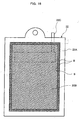
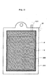
- a submerged membrane unit as shown in Fig. 15.
- a membrane unit 21 a plurality of plate-like membrane cartridges 22, and a diffuser 23 that flows a membrane surface cleaning air from the bottom of the membrane cartridges 22, are disposed in a case 24.
- the case 24 consists of a membrane case 25 and a diffuser case 26, and it is designed so that the entire air dispersed from the diffuser 23 to clean membrane surface enters into the membrane case 25.
- a membrane 22B is disposed on both surfaces of a supporting plate 22A made of ABS resin, and the membranes 22B are sealed, at a water sealing portion S of the periphery, to the supporting plate 22A by supersonic welding.
- a permeate passage is formed between the supporting plate 22A and membrane 22B, and inside of the supporting plate 22A, and a nozzle 22C connected to the permeate passage is formed at an upper edge of the supporting plate 22A.
- Each membrane cartridge 22 is connected, via a tube 27 connected to the nozzel 22C, to a manifold 28.
- a permeate discharge pipe 29 that discharges the liquid transmitted through the membrane is connected to the manifold 28.
- a membrane unit 21 When a membrane unit 21 is used in an activated sludge treatment plant, the membrane unit 21 is submerged in a mixed liquor of activated sludge in an aeration tank, organic substances and nitrogen in raw water are treated with the activated sludge, under the condition that an aerated air is dispersed from an diffuser 23.
- the mixed liquor of activated sludge is subjected to gravity filtration by the membrane cartridges 22 by using the water head in the aeration tank as a driving pressure (alternatively, a suction filtration may be conducted by interposing a suction pump in a permeate discharge pipe 29), and the permeate through the membrane surface of the membrane cartridges 22 is discharged, as a treated water, via the permeate discharge pipe to the outside of the tank.
- the bubble swarm dispersed from the diffuser 23, and an upward current caused by the bubbling will flow a narrow watercourse (5 to 10 mm in width) between the adjacent membrane cartridges 22.
- the membrane surfaces of the membrane cartridges 22 are cleaned to suppress a separation function reduction, thereby preventing a malfunction of the membrane unit 21.
- One of ultrasonic welding processes is a rotary welding.
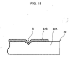
- a membrane 22B is disposed so as to cover the surface of a supporting plate 22A, a rotary horn 31 is rotated while it presses the membrane 22B against the supporting plate 22A and, by the ultrasonic generated from the rotary horn 31, the membrane 22B is sealed to the supporting plate 22A, thereby to form a water sealing portion S and auxiliary fixing portion B.
- the supporting plate 22A is melted at the water sealing portion S, to make a dent in the form of a groove, as shown in Fig. 18. Since the membrane 22B is sealed to the supporting plate 22A so as to bite into the plate 22A, the membrane 22B is damaged at the time of welding, which is susceptible to a fatigue failure.
- a linear welding allowance 32 and zonal auxiliary welding allowance 33 for forming a water sealing portion S are previously formed on the surface of a supporting plate 22A, so as to project therefrom, a membrane 22B is disposed so as to cover the welding allowance 32 and auxiliary welding allowance 33, and an up-down horn 34 is pressed against the welding allowances 32 and 33, from above the membrane 22B.
- the up-down horn 34 has, on its bottom facing to the membrane 22B, a pattern 34a.
- the pattern 34a is formed in such a manner that 0.3-mm-high regular quadrangular pyramids are positioned from one another by a pitch of 0.6 mm.
- the membrane 22B is sealed to the supporting plate 22A at the welding allowances 32 and 33, to form a linear water sealing portion S and auxiliary fixing portion B.
- the membrane 22B is obtained by forming an organic substance on the front and rear surfaces of a nonwoven fabric serving as a substrate. Its mechanical strength is ensured by the nonwoven fabric. Therefore, in the foregoing method, the membrane 22B is locally pressed at the position corresponding to the top of the pattern 34a of the up-down horn 34, and an excessive energy is concentrated at that position. Thereby, the fabric of the nonwoven fabric is easily broken and its mechanical strength is thus impaired.
- a submerged membrane cartridge comprising a supporting plate made of a resin, and a membrane disposed so as to cover the surface of the supporting plate, characterized in that the membrane is fused in a plurality of welding allowances formed, in multiple, along the periphery of the supporting plate; an inner fixing portion that retains the membrane under tension is formed by an inner welding allowance; a water sealing portion that ensures a sealing function through the entire periphery of the membrane is formed by a central welding allowance; and an outer fixing portion that fixes the periphery of the membrane to the supporting plate is formed by an outer welding allowance.
- the submerged membrane cartridge is submerged in a reaction tank and used in the state that an aeration is made from the bottom.
- a gas-liquid-solid mixed phase upward flow that is derived from the aeration will flow along the membrane surface. Therefore, the vibration caused by the gas-liquid-solid mixed phase upward flow is exert on the submerged membrane cartridge.
- the service environment of the submerged membrane cartridge in the reaction tank is varied depending on the shape of the reaction tank, the property of a liquid treated that is stored in the reaction tank, seasonal variable factors, and the like. Thus, depending on the change in the service environment, an eventual external force might be exerted on the submerged membrane cartridge.
- the inner fixing portion that retains the membrane under tension, and the outer fixing portion that fixes the periphery of the membrane to the supporting plate, have a sufficient strength to the external force exerted on the membrane in the usual service condition. Therefore, by receiving an external force at the inner fixing portion and the outer fixing portion, no external force reaches the water sealing portion, thus preventing damage to the water sealing portion.
- the submerged membrane cartridge has an improved durability against aeration.
- the outer fixing portion is shaped like a mesh.
- the membrane is fused through its entire periphery to the supporting plate, in the inner fixing portion, water sealing portion and outer fixing portion.
- the membrane is formed by providing an organic membrane on the front and rear surfaces of a membrane substrate made of a nonwoven fabric, and a fusing layer reaching the topt layer on the welding surface side of the membrane substrate is formed in the inner fixing portion, water sealing portion and outer fixing portion.
- the membrane in the event that the membrane peels at the inner or outer fixing portion, due to vibration fatigue and eventual external force, the membrane separates from the inner or outer fixing portion, without causing a breakage of the membrane substrate. This facilitates to repair the membrane.
- a submerged membrane cartridge which comprises:
- a submerged membrane cartridge in one preferred embodiment is for use in an submerged membrane unit.
- the basic structure of the membrane unit is the same as that previously described by referring to Fig. 15. Therefore, like parts are identified by the same reference numerals as in Fig. 15, and its description is omitted.
- a supporting plate 41 of a submerged membrane cartridge 40 is composed of an ABS resin, and it has a shape of 490 mm wide, 1000 mm long, and 6 mm high.
- the linear welding allowances 42a and 42b have a height in the range of 0.4 to 0.6 mm.
- the mesh-like welding allowance 43 corresponds to the periphery of the membrane 44, and is lower than the linear welding allowances 42a and 42b by the amount of about 0.1 mm.
- the welding allowance 43 is formed by overlapping three irregular-line trails 43a, 43b and 43c.
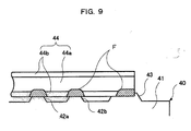
- a membrane 44 is disposed on the front and rear surfaces of the supporting plate 41, so as to cover the linear welding allowances 42a, 42b and the mesh-like welding allowance 43.
- the membrane 44 is formed by providing an organic membrane 44b on the front and rear of a substrate 44a composed of a nonwoven fabric.
- the supporting plate 41 provided with the membrane 44 is disposed on a fixture 45, and the mesh-like welding allowance 43 underlying the supporting plate 41 is supported by the fixture 45, with the membrane 44 interposed.
- an up-down horn 46 is pressed against the liner welding allowances 42a and 42b, and the mesh-like welding allowance 43.
- the up-down horn 46 causes ultrasonic vibration, and its bottom surface facing to the membrane 44 forms a flat surface.
- the membrane 44 By vibrating the up-down horn 46 using a ultrasonic, the membrane 44 is fused at the linear welding allowances 42a, 42b and the mesh-like welding allowance 43. At that time, since the mesh-like welding allowance 43 is lower than the linear welding allowances 42a and 42b, the membrane 44 is sandwiched by the up-down horn 46 and the linear welding allowances 42a and 42b, on the top surface of the supporting plate 41, and the membrane 44 has no contact with the mesh-like welding allowance 43. Therefore, in the linear welding allowances 42a and 42b, a fusion occurs between the membrane 44 and supporting plate 41, thereby providing a sufficiently strong welding. In the mesh-like welding allowance 43, a fusion occurs only at a high position, which is caused by an error in height.
- the fusion between the membrane 44 and supporting plate 41 is limited to the mesh-like welding allowance 43, thereby providing a sufficiently strong welding.
- the supporting plate 41 having the membrane 44 is reversed so that it is disposed on the fixture 45 again, and a welding is conducted again in the same procedure.
- a fusing layer F reaching the top layer on the welding surface side of a membrane substrate 44a is formed at an inner fixing portion A, water sealing portion S, and outer fixing portion C. Therefore, the pressure (0.2 to 0.6 MPa), amplitude (30 to 60 ⁇ m) and oscillation time (0.1 to 0.5 sec.) of the up-down horn 46 are set.
- the membrane 44 is fused in the linear welding allowances 42a, 42b and the mesh-like welding allowance 43, each projecting from the surface of the supporting plate 41, thereby to form the inner fixing portion A, the water sealing portion S and the outer fixing portion C.
- This construction enables to prevent the membrane 44 from being deteriorated due to an excess energy concentration, and to prevent the occurrence of knurling flaw as has been conventional.
- the wide mesh-like welding allowance 43 tends to have an irregular height. Therefore, when the flat surface of the up-down horn 46 presses against the linear welding allowances 42a and 42b and the mesh-like welding allowance 43 at the same time, a fusing layer F of the outer fixing portion C in the mesh-like welding allowance 43 will become insufficient and thus discontinuous, alternatively, a fusing layer F of the inner fixing portion A and water sealing portion S in the linear welding allowances 42a and 42b will becomes excessive. As a result, it is difficult to form an appropriate fusing layer F in the inner fixing portion A, water sealing portion S and outer fixing portion C, at the same time.
- an appropriate fusing layer F can be formed in the inner fixing portion A, water sealing portion S and outer fixing portion C by performing a suitable welding according to the characteristic of each welding allowance by using the linear welding allowances 42a, 42b and the mesh-like welding allowance 43 which have different heights one another, and by performing a fusing procedure of the front and rear of the supporting plate 41, respectively.
- a linear inner fixing portion A is formed at the inner linear welding allowance 42a, and a water sealing portion S is formed at the central linear welding allowance 42b, and an effective filtration area of the membrane 44 surrounded by the fused inner fixing portion A and water sealing portion S is retained under tension.
- the outer fixing portion C disposed at the mesh-like welding allowance 43 intermittently fixes the periphery of the membrane 44 to the supporting plate 41.
- the inner fixing portion A, water sealing portion S and outer fixing portion C are so shaped that their respective trajectories are continuous through the entire periphery of the membrane 44.
- the membrane 44 is fused through its entire periphery to the supporting plate 41, thereby to accomplish a sealing function.
- the outer fixing portion C is sealed in multiple by three trajectories 43a, 43b and 43c.
- the outer fixing portion C is not necessarily required to have a sealing function, but it can be formed so as to have a discontinuous trajectory.
- a submerged membrane cartridge 40 is fit in a case 24 of a membrane unit 21, and it is submerged in an aeration tank and then used under the condition that an aeration is conducted from the bottom.
- a gas-liquid-solid mixed phase upward flow that is derived from the aeration will flow along the membrane surface. Therefore, vibration caused by the gas-liquid-solid mixed phase upward flow is exerted on the submerged membrane cartridge 40.
- a high load to be caused by the aeration upon termination of filtration is exerted on the submerged membrane cartridge 40, and the repetitive stress due to this load is concentrated in the vicinity of the boundary between the membrane 44 and supporting plate 41 at the inner fixing portion A.
- the service environment of the submerged membrane cartridge 40 in the aeration tank is varied depending on the shape of the aeration tank, the property of a liquid to be treated that is stored in the aeration tank, seasonal variable factors, and the like. Thus, depending on the change in the service environment, an eventual external force might exert on the submerged membrane cartridge 40.
- the inner fixing portion A that retains the membrane 44 under tension, and the outer fixing portion C that fixes the periphery of the membrane 44 to the supporting plate 41, have a sufficient strength to an external force exerted on the membrane 44 in the usual service conditions. Therefore, any external force is received at the inner fixing portion A and the outer fixing portion C, thereby it is able to prevent the external force from reaching the water sealing portion S, and thus prevent damage to the water sealing portion S.
- the inner fixing portion A and outer fixing portion C act as a protector against an external force, even when the membrane 44 peels at the inner fixing portion A or the outer fixing portion C, because of vibration fatigue and eventual external force, the water sealing portion S does not peel at the same time, and it is therefore able to prevent the filtration performance of the submerged membrane cartridge 40 from being damaged at an eventual circumstance. Thereby, the submerged membrane cartridge 40 has an improved durability against aeration.
- the outer fixing portion C By shaping the outer fixing portion C like a mesh, the periphery of the membrane 44 is welded at the outer fixing portion C having a predetermined width. Therefore, the dimensional errors of the membrane 44 and the supporting plate 41 can be cancelled at the outer fixing portion C.
- the inner fixing portion A, water sealing portion S and outer fixing portion C accomplish a sealing function, thereby the sealing function is ensured in multiple.
- a fusing layer F reaching the top surface of the membrane substrate 44a is formed by welding in the inner fixing portion A, water sealing portion S and outer fixing portion C, even when the membrane 44 peels at the inner fixing portion A and outer fixing portion C, due to vibration fatigue and eventual external force, the membrane 44 can maintain the function as a membrane. Specifically, before the membrane 44 is broken at the water sealing portion S, it comes off from the inner fixing portion A or outer fixing portion C, without causing a breakage of the membrane substrate 44a. Therefore, the life of the membrane cartridge 40 is extended by repairing the peeled inner fixing portion A or outer fixing portion C at the time of checking or the like.
- a peeling test for the strength of welding will be described hereinafter. As shown in Fig. 5, the peeling test is conducted in the following manner that the membrane 44 fused to the supporting plate 41 (test specimens cut in a predetermined width) is vertically pulled with respect to the supporting plate 41.
- a fusing layer F that reaches a deep position in a membrane substrate 44a of the membrane 44 is formed in an inner fixing portion A, water sealing portion S and outer fixing portion C, the membrane 44 is broken at the inner fixing portion A, as shown in Fig. 7.
- the peak of strength is high, however, a rapid breakage takes place as is apparent from the correlation between tensile strength and tensile time in Fig. 8.
- a fusing layer F that reaches a shallow position in a membrane substrate 44a of the membrane 44 is formed in an inner fixing portion A, water sealing portion S and outer fixing portion C, the membrane 44 is broken at the membrane substrate 44a as shown in Fig. 10.
- the peak of strength is lower than the case of fusing strongly and, after the inner fixing portion A peels at the water sealing portion S and outer fixing portion C are successively broken and peel at the membrane substrate 44a, thus making it impossible to repair.
- a fusing layer F reaching the top layer on the welding surface side of the membrane substrate 44a of the membrane 44 is formed by fusing in an inner fixing portion A, water sealing portion S and outer fixing portion C, the membrane 44 peels on the front surface on the welding side of the membrane substrate 44a.
- the peak of strength is lower than the case of fusing strongly, however, a predetermined fusing strength is retained at the water sealing portion S even after the inner fixing portion A comes off. This enables to extend the life of the submerged membrane cartridge 40.
- the inner fixing portion that retains the membrane under tension state, and the outer fixing portion that fixes the periphery of the membrane to the supporting plate act as a protector against an external force exerted to the membrane in the usual service conditions. Therefore, any external force cannot be exerted on the water sealing portion, thereby avoiding damage to the water sealing portion. Even if the membrane peels at the inner and outer fixing portions due to vibration fatigue and eventual external force, the water sealing portion does not peel at the same time, and the submerged membrane cartridge has an improved durability against aeration.
- the former or later is repaired to recover its protecting function for preventing the peeling of the water sealing portion, thereby extending the life of the submerged membrane.
- the outer fixing portion like a mesh
- the sealing function can be ensured in multiple by arranging so that the membrane is fused to the supporting plate through its entire periphery in the inner fixing portion, water sealing portion and outer fixing portion.
Landscapes
- Engineering & Computer Science (AREA)
- Mechanical Engineering (AREA)
- Chemical & Material Sciences (AREA)
- Chemical Kinetics & Catalysis (AREA)
- Water Supply & Treatment (AREA)
- Textile Engineering (AREA)
- Manufacturing & Machinery (AREA)
- Separation Using Semi-Permeable Membranes (AREA)
- Activated Sludge Processes (AREA)
Applications Claiming Priority (2)
| Application Number | Priority Date | Filing Date | Title |
|---|---|---|---|
| JP2000026887A JP3778758B2 (ja) | 2000-02-04 | 2000-02-04 | 浸漬型膜カートリッジの製造方法 |
| EP00109662A EP1121971A3 (de) | 2000-02-04 | 2000-05-06 | Tauchmembrankassette und dessen Herstellungsverfahren |
Related Parent Applications (1)
| Application Number | Title | Priority Date | Filing Date |
|---|---|---|---|
| EP00109662A Division EP1121971A3 (de) | 2000-02-04 | 2000-05-06 | Tauchmembrankassette und dessen Herstellungsverfahren |
Publications (2)
| Publication Number | Publication Date |
|---|---|
| EP1728546A2 true EP1728546A2 (de) | 2006-12-06 |
| EP1728546A3 EP1728546A3 (de) | 2006-12-20 |
Family
ID=18552550
Family Applications (2)
| Application Number | Title | Priority Date | Filing Date |
|---|---|---|---|
| EP06008357A Ceased EP1728546A3 (de) | 2000-02-04 | 2000-05-06 | Tauchmembrankassette und deren Herstellungsverfahren |
| EP00109662A Withdrawn EP1121971A3 (de) | 2000-02-04 | 2000-05-06 | Tauchmembrankassette und dessen Herstellungsverfahren |
Family Applications After (1)
| Application Number | Title | Priority Date | Filing Date |
|---|---|---|---|
| EP00109662A Withdrawn EP1121971A3 (de) | 2000-02-04 | 2000-05-06 | Tauchmembrankassette und dessen Herstellungsverfahren |
Country Status (4)
| Country | Link |
|---|---|
| US (1) | US6287467B1 (de) |
| EP (2) | EP1728546A3 (de) |
| JP (1) | JP3778758B2 (de) |
| CA (1) | CA2311355C (de) |
Cited By (3)
| Publication number | Priority date | Publication date | Assignee | Title |
|---|---|---|---|---|
| CN103508558A (zh) * | 2013-07-16 | 2014-01-15 | 中石化宁波工程有限公司 | 一种淹没式模架 |
| CN104001425A (zh) * | 2014-04-30 | 2014-08-27 | 山东中保康医疗器具有限公司 | 血浆去白细胞滤器用不亲水膜透水机 |
| EP3721974A4 (de) * | 2017-12-04 | 2021-09-22 | Kubota Corporation | Flachmembranelement und verfahren zu seiner herstellung |
Families Citing this family (29)
| Publication number | Priority date | Publication date | Assignee | Title |
|---|---|---|---|---|
| DE602004013731D1 (de) * | 2003-03-05 | 2008-06-26 | Hydranautics | Tauchbares membranmodul mit austauschbaren membranelementen |
| US6986428B2 (en) * | 2003-05-14 | 2006-01-17 | 3M Innovative Properties Company | Fluid separation membrane module |
| US7279215B2 (en) * | 2003-12-03 | 2007-10-09 | 3M Innovative Properties Company | Membrane modules and integrated membrane cassettes |
| EP1625885A1 (de) | 2004-08-11 | 2006-02-15 | Vlaamse Instelling Voor Technologisch Onderzoek (Vito) | Membran mit integriertem Permeatkanal |
| JP5079984B2 (ja) | 2005-02-23 | 2012-11-21 | 株式会社Gsユアサ | 膜エレメントの製造方法 |
| US20060191837A1 (en) * | 2005-02-28 | 2006-08-31 | Alfa Laval Corporate Ab | Permeate spacer module |
| JP2008531269A (ja) * | 2005-02-28 | 2008-08-14 | アルファ ラヴァル コーポレイト アクチボラゲット | 透過液スペーサモジュール |
| JP2007181779A (ja) | 2006-01-06 | 2007-07-19 | Hitachi Plant Technologies Ltd | 平膜エレメントの製造方法 |
| DE502007005904D1 (de) * | 2007-09-19 | 2011-01-20 | Freudenberg Carl Kg | Separatorplatte |
| JP5187055B2 (ja) * | 2008-08-04 | 2013-04-24 | 東レ株式会社 | 膜エレメントおよびその製造方法 |
| JP2010042375A (ja) * | 2008-08-18 | 2010-02-25 | Toray Ind Inc | 膜エレメントおよびその製造方法ならびに樹脂板 |
| CN101940881B (zh) * | 2009-07-07 | 2012-05-30 | 上海斯纳普膜分离科技有限公司 | 平片式滤膜元件封接方法 |
| CN102481522B (zh) * | 2009-08-28 | 2014-09-24 | 陶氏环球技术有限责任公司 | 包含具有毛细管通道的膜片材的过滤组件 |
| IN2012DN01794A (de) | 2009-09-03 | 2015-06-05 | Vito | |
| JP5603111B2 (ja) * | 2010-03-17 | 2014-10-08 | 志摩環境事業協業組合 | 平板状膜エレメント及びそれを用いた浸漬型膜分離装置 |
| CN102892576B (zh) | 2010-04-20 | 2016-02-10 | 法伊布拉卡斯特有限公司 | 成形的板膜元件和过滤系统 |
| KR101136025B1 (ko) * | 2010-05-17 | 2012-04-18 | 주식회사 퓨어엔비텍 | 여과막모듈 |
| US8114478B1 (en) | 2010-09-17 | 2012-02-14 | Dow Global Technologies Llc | Dual-sided membrane sheet and method for making the same |
| CN102173052B (zh) * | 2010-12-08 | 2013-12-18 | 上海斯纳普膜分离科技有限公司 | 热板熔接机及平片式滤膜元件封接方法 |
| GB201021524D0 (en) | 2010-12-20 | 2011-02-02 | Univ Leuven Kath | Fouling control in membrane filtration processes by magnetic field induced membrane vibration |
| KR102015613B1 (ko) | 2011-10-20 | 2019-08-28 | 파이브라케스트 리미티드 | 성형 시이트 막 요소를 코팅하기 위한 코팅 기기 및 공정 |
| JP6300602B2 (ja) * | 2014-03-31 | 2018-03-28 | 株式会社クボタ | 平膜エレメントの製造方法および平膜エレメント |
| GR1008540B (el) | 2014-06-27 | 2015-07-28 | Κωνσταντινος Χατζηκωνσταντινου | Χρηση υψηλης συχνοτητας μηχανικης δονησης για την βελτιωση λειτουργιας διεργασιων διαχωρισμου ρευστων με μεμβρανες |
| WO2017049408A1 (en) | 2015-09-24 | 2017-03-30 | Fibracast Ltd. | Method of operating membrane filter |
| US12343682B2 (en) | 2018-07-03 | 2025-07-01 | Fibracast Ltd. | Tightly spaced flat sheet immersed membranes and fine bubble aeration |
| IL289660A (en) | 2019-07-16 | 2022-07-01 | Fibracast Ltd | System and method for feeding submerged membrane units |
| WO2021059885A1 (ja) * | 2019-09-26 | 2021-04-01 | 東洋紡株式会社 | 浸漬型平膜エレメントおよびその製造方法 |
| CN111603941B (zh) * | 2020-05-25 | 2024-12-27 | 厦门世脉科技有限公司 | 一种平板膜元件及其制备方法 |
| JP7695114B2 (ja) | 2021-06-11 | 2025-06-18 | 株式会社クボタ | 膜カートリッジおよび膜カートリッジの製造方法 |
Family Cites Families (8)
| Publication number | Priority date | Publication date | Assignee | Title |
|---|---|---|---|---|
| US4952317A (en) * | 1989-03-10 | 1990-08-28 | Bradley Culkin | Device and method for filtering a colloidal suspension |
| FR2662114B1 (fr) * | 1990-05-15 | 1994-04-29 | Eurodia Sa | Procede de fabrication d'un cadre separateur pour empilement dans un dispositif d'echange. |
| US5651888A (en) * | 1992-12-16 | 1997-07-29 | Kubota Corporation | Filtration membrane cartridge |
| US5624555A (en) * | 1993-10-04 | 1997-04-29 | National Research Council Of Canada | Fluid fractionating, stacked permeable membrane assembly |
| US5772831A (en) * | 1995-04-03 | 1998-06-30 | Kubota Corporation | Filter membrane element and method of manufacturing same |
| JPH09117645A (ja) * | 1995-10-24 | 1997-05-06 | Kurita Water Ind Ltd | 浸漬型膜分離装置の平膜エレメント |
| JPH10202069A (ja) * | 1997-01-17 | 1998-08-04 | Nitto Denko Corp | 平膜エレメント |
| JPH11235519A (ja) * | 1998-02-24 | 1999-08-31 | Kubota Corp | 膜カートリッジ |
-
2000
- 2000-02-04 JP JP2000026887A patent/JP3778758B2/ja not_active Expired - Lifetime
- 2000-04-06 US US09/544,064 patent/US6287467B1/en not_active Expired - Lifetime
- 2000-05-06 EP EP06008357A patent/EP1728546A3/de not_active Ceased
- 2000-05-06 EP EP00109662A patent/EP1121971A3/de not_active Withdrawn
- 2000-06-13 CA CA002311355A patent/CA2311355C/en not_active Expired - Lifetime
Cited By (6)
| Publication number | Priority date | Publication date | Assignee | Title |
|---|---|---|---|---|
| CN103508558A (zh) * | 2013-07-16 | 2014-01-15 | 中石化宁波工程有限公司 | 一种淹没式模架 |
| CN104001425A (zh) * | 2014-04-30 | 2014-08-27 | 山东中保康医疗器具有限公司 | 血浆去白细胞滤器用不亲水膜透水机 |
| CN104001425B (zh) * | 2014-04-30 | 2015-11-18 | 山东中保康医疗器具有限公司 | 血浆去白细胞滤器用不亲水膜透水机 |
| EP3721974A4 (de) * | 2017-12-04 | 2021-09-22 | Kubota Corporation | Flachmembranelement und verfahren zu seiner herstellung |
| TWI774888B (zh) * | 2017-12-04 | 2022-08-21 | 日商久保田股份有限公司 | 平膜元件及其製造方法 |
| US12521679B2 (en) | 2017-12-04 | 2026-01-13 | Kubota Corporation | Flat membrane element and method for producing same |
Also Published As
| Publication number | Publication date |
|---|---|
| CA2311355A1 (en) | 2001-08-04 |
| EP1121971A2 (de) | 2001-08-08 |
| CA2311355C (en) | 2007-09-18 |
| JP2001212436A (ja) | 2001-08-07 |
| JP3778758B2 (ja) | 2006-05-24 |
| EP1728546A3 (de) | 2006-12-20 |
| EP1121971A3 (de) | 2001-08-22 |
| US6287467B1 (en) | 2001-09-11 |
Similar Documents
| Publication | Publication Date | Title |
|---|---|---|
| US6287467B1 (en) | Submerged membrane cartridge | |
| EP1366804B1 (de) | Verfahren zum Ersetzen einer Filtrationsmembran einer Filterpatrone für Belebtschlamm | |
| CN102470323A (zh) | 用于过滤的平膜元件、平膜型分离膜组件以及过滤装置 | |
| JP5611032B2 (ja) | 浸漬型膜分離装置 | |
| JP2010149064A (ja) | 浸漬型膜分離装置 | |
| JP6300602B2 (ja) | 平膜エレメントの製造方法および平膜エレメント | |
| US10328394B2 (en) | Membrane cartridge and membrane-cartridge production method | |
| JP2008049239A (ja) | 膜エレメント | |
| JP6215551B2 (ja) | 膜カートリッジ | |
| JP4969079B2 (ja) | 浸漬型膜カートリッジの膜周縁固定構造 | |
| JP3576050B2 (ja) | 浸漬型膜カートリッジの製造方法 | |
| JP2006007223A (ja) | 浸漬型膜カートリッジ | |
| CN114514064A (zh) | 浸渍型平膜元件及其制造方法 | |
| JP2001120959A (ja) | 浸漬型膜カートリッジの製造方法 | |
| JP2002275693A (ja) | 電解メッキ装置用セパレート膜体およびその製造方法と電解メッキ装置 | |
| JPH11309345A (ja) | 浸漬型膜分離装置の集合管構造 | |
| JPH11235519A (ja) | 膜カートリッジ | |
| JP3059943U (ja) | フィルタサポートおよび微生物補集用濾過装置 | |
| JP2009045559A (ja) | 膜エレメント、膜エレメントの製造方法および膜分離装置 | |
| JP2000107576A (ja) | 活性汚泥用膜カートリッジの再生方法 | |
| JPH0724270A (ja) | 膜エレメントの溶着方法 | |
| JP3028899B2 (ja) | 膜モジュールの製造方法 | |
| JPH078007Y2 (ja) | 濾過装置の濾過筒保持装置 | |
| JPH09122456A (ja) | 膜カートリッジ | |
| KR101391681B1 (ko) | 여과 농축 장치 |
Legal Events
| Date | Code | Title | Description |
|---|---|---|---|
| PUAI | Public reference made under article 153(3) epc to a published international application that has entered the european phase |
Free format text: ORIGINAL CODE: 0009012 |
|
| PUAL | Search report despatched |
Free format text: ORIGINAL CODE: 0009013 |
|
| AC | Divisional application: reference to earlier application |
Ref document number: 1121971 Country of ref document: EP Kind code of ref document: P |
|
| AK | Designated contracting states |
Kind code of ref document: A2 Designated state(s): DE FR GB IT |
|
| AK | Designated contracting states |
Kind code of ref document: A3 Designated state(s): DE FR GB IT |
|
| RIN1 | Information on inventor provided before grant (corrected) |
Inventor name: YAMADA, YUTAKA Inventor name: UEJIMA, TATSUYA,KUBOTA CORPORATION Inventor name: IZUMI, KIYOSHI,KUBOTA CORPORATION Inventor name: NAGANO, MASAAKI,KUBOTA CORPORATION Inventor name: OKAJIMA, YASUNOBU,KUBOTA CORPORATION |
|
| 17P | Request for examination filed |
Effective date: 20070620 |
|
| 17Q | First examination report despatched |
Effective date: 20070718 |
|
| AKX | Designation fees paid |
Designated state(s): DE FR GB IT |
|
| STAA | Information on the status of an ep patent application or granted ep patent |
Free format text: STATUS: THE APPLICATION HAS BEEN REFUSED |
|
| 18R | Application refused |
Effective date: 20091225 |