EP1728691A2 - Dispositif d'airbag pour véhicule - Google Patents
Dispositif d'airbag pour véhicule Download PDFInfo
- Publication number
- EP1728691A2 EP1728691A2 EP06114763A EP06114763A EP1728691A2 EP 1728691 A2 EP1728691 A2 EP 1728691A2 EP 06114763 A EP06114763 A EP 06114763A EP 06114763 A EP06114763 A EP 06114763A EP 1728691 A2 EP1728691 A2 EP 1728691A2
- Authority
- EP
- European Patent Office
- Prior art keywords
- fracture
- opening
- airbag
- interior panel
- hinge
- Prior art date
- Legal status (The legal status is an assumption and is not a legal conclusion. Google has not performed a legal analysis and makes no representation as to the accuracy of the status listed.)
- Withdrawn
Links
- 230000002787 reinforcement Effects 0.000 claims abstract description 50
- 238000003466 welding Methods 0.000 claims description 15
- 239000000758 substrate Substances 0.000 claims description 11
- 229920003002 synthetic resin Polymers 0.000 claims description 9
- 239000000057 synthetic resin Substances 0.000 claims description 9
- 239000010410 layer Substances 0.000 claims description 7
- 239000006260 foam Substances 0.000 claims description 6
- 239000002344 surface layer Substances 0.000 claims description 6
- 229920005989 resin Polymers 0.000 claims description 4
- 239000011347 resin Substances 0.000 claims description 4
- 230000008878 coupling Effects 0.000 claims description 2
- 238000010168 coupling process Methods 0.000 claims description 2
- 238000005859 coupling reaction Methods 0.000 claims description 2
- 230000003014 reinforcing effect Effects 0.000 claims description 2
- 238000000034 method Methods 0.000 description 9
- 239000004743 Polypropylene Substances 0.000 description 7
- 229920001155 polypropylene Polymers 0.000 description 7
- 230000008569 process Effects 0.000 description 6
- 239000000463 material Substances 0.000 description 5
- -1 polypropylene Polymers 0.000 description 5
- 229920002397 thermoplastic olefin Polymers 0.000 description 4
- 230000004308 accommodation Effects 0.000 description 2
- 230000000694 effects Effects 0.000 description 2
- 239000002184 metal Substances 0.000 description 2
- 230000009471 action Effects 0.000 description 1
- 239000000853 adhesive Substances 0.000 description 1
- 230000001070 adhesive effect Effects 0.000 description 1
- 239000003365 glass fiber Substances 0.000 description 1
- 238000007689 inspection Methods 0.000 description 1
- 230000002452 interceptive effect Effects 0.000 description 1
- 238000003698 laser cutting Methods 0.000 description 1
- 230000004048 modification Effects 0.000 description 1
- 238000012986 modification Methods 0.000 description 1
- 229920005673 polypropylene based resin Polymers 0.000 description 1
- 239000012779 reinforcing material Substances 0.000 description 1
- 239000000454 talc Substances 0.000 description 1
- 229910052623 talc Inorganic materials 0.000 description 1
- 210000005239 tubule Anatomy 0.000 description 1
Images


Classifications
-
- B—PERFORMING OPERATIONS; TRANSPORTING
- B60—VEHICLES IN GENERAL
- B60R—VEHICLES, VEHICLE FITTINGS, OR VEHICLE PARTS, NOT OTHERWISE PROVIDED FOR
- B60R21/00—Arrangements or fittings on vehicles for protecting or preventing injuries to occupants or pedestrians in case of accidents or other traffic risks
- B60R21/02—Occupant safety arrangements or fittings, e.g. crash pads
- B60R21/16—Inflatable occupant restraints or confinements designed to inflate upon impact or impending impact, e.g. air bags
- B60R21/20—Arrangements for storing inflatable members in their non-use or deflated condition; Arrangement or mounting of air bag modules or components
- B60R21/215—Arrangements for storing inflatable members in their non-use or deflated condition; Arrangement or mounting of air bag modules or components characterised by the covers for the inflatable member
- B60R21/2165—Arrangements for storing inflatable members in their non-use or deflated condition; Arrangement or mounting of air bag modules or components characterised by the covers for the inflatable member characterised by a tear line for defining a deployment opening
-
- B—PERFORMING OPERATIONS; TRANSPORTING
- B60—VEHICLES IN GENERAL
- B60R—VEHICLES, VEHICLE FITTINGS, OR VEHICLE PARTS, NOT OTHERWISE PROVIDED FOR
- B60R21/00—Arrangements or fittings on vehicles for protecting or preventing injuries to occupants or pedestrians in case of accidents or other traffic risks
- B60R21/02—Occupant safety arrangements or fittings, e.g. crash pads
- B60R21/16—Inflatable occupant restraints or confinements designed to inflate upon impact or impending impact, e.g. air bags
- B60R21/20—Arrangements for storing inflatable members in their non-use or deflated condition; Arrangement or mounting of air bag modules or components
- B60R21/205—Arrangements for storing inflatable members in their non-use or deflated condition; Arrangement or mounting of air bag modules or components in dashboards
-
- B—PERFORMING OPERATIONS; TRANSPORTING
- B29—WORKING OF PLASTICS; WORKING OF SUBSTANCES IN A PLASTIC STATE IN GENERAL
- B29C—SHAPING OR JOINING OF PLASTICS; SHAPING OF MATERIAL IN A PLASTIC STATE, NOT OTHERWISE PROVIDED FOR; AFTER-TREATMENT OF THE SHAPED PRODUCTS, e.g. REPAIRING
- B29C65/00—Joining or sealing of preformed parts, e.g. welding of plastics materials; Apparatus therefor
- B29C65/02—Joining or sealing of preformed parts, e.g. welding of plastics materials; Apparatus therefor by heating, with or without pressure
- B29C65/06—Joining or sealing of preformed parts, e.g. welding of plastics materials; Apparatus therefor by heating, with or without pressure using friction, e.g. spin welding
-
- B—PERFORMING OPERATIONS; TRANSPORTING
- B29—WORKING OF PLASTICS; WORKING OF SUBSTANCES IN A PLASTIC STATE IN GENERAL
- B29C—SHAPING OR JOINING OF PLASTICS; SHAPING OF MATERIAL IN A PLASTIC STATE, NOT OTHERWISE PROVIDED FOR; AFTER-TREATMENT OF THE SHAPED PRODUCTS, e.g. REPAIRING
- B29C66/00—General aspects of processes or apparatus for joining preformed parts
- B29C66/50—General aspects of joining tubular articles; General aspects of joining long products, i.e. bars or profiled elements; General aspects of joining single elements to tubular articles, hollow articles or bars; General aspects of joining several hollow-preforms to form hollow or tubular articles
- B29C66/51—Joining tubular articles, profiled elements or bars; Joining single elements to tubular articles, hollow articles or bars; Joining several hollow-preforms to form hollow or tubular articles
- B29C66/53—Joining single elements to tubular articles, hollow articles or bars
- B29C66/532—Joining single elements to the wall of tubular articles, hollow articles or bars
-
- B—PERFORMING OPERATIONS; TRANSPORTING
- B29—WORKING OF PLASTICS; WORKING OF SUBSTANCES IN A PLASTIC STATE IN GENERAL
- B29C—SHAPING OR JOINING OF PLASTICS; SHAPING OF MATERIAL IN A PLASTIC STATE, NOT OTHERWISE PROVIDED FOR; AFTER-TREATMENT OF THE SHAPED PRODUCTS, e.g. REPAIRING
- B29C66/00—General aspects of processes or apparatus for joining preformed parts
- B29C66/50—General aspects of joining tubular articles; General aspects of joining long products, i.e. bars or profiled elements; General aspects of joining single elements to tubular articles, hollow articles or bars; General aspects of joining several hollow-preforms to form hollow or tubular articles
- B29C66/51—Joining tubular articles, profiled elements or bars; Joining single elements to tubular articles, hollow articles or bars; Joining several hollow-preforms to form hollow or tubular articles
- B29C66/54—Joining several hollow-preforms, e.g. half-shells, to form hollow articles, e.g. for making balls, containers; Joining several hollow-preforms, e.g. half-cylinders, to form tubular articles
-
- B—PERFORMING OPERATIONS; TRANSPORTING
- B29—WORKING OF PLASTICS; WORKING OF SUBSTANCES IN A PLASTIC STATE IN GENERAL
- B29L—INDEXING SCHEME ASSOCIATED WITH SUBCLASS B29C, RELATING TO PARTICULAR ARTICLES
- B29L2031/00—Other particular articles
- B29L2031/30—Vehicles, e.g. ships or aircraft, or body parts thereof
- B29L2031/3005—Body finishings
- B29L2031/3038—Air bag covers
-
- B—PERFORMING OPERATIONS; TRANSPORTING
- B60—VEHICLES IN GENERAL
- B60R—VEHICLES, VEHICLE FITTINGS, OR VEHICLE PARTS, NOT OTHERWISE PROVIDED FOR
- B60R21/00—Arrangements or fittings on vehicles for protecting or preventing injuries to occupants or pedestrians in case of accidents or other traffic risks
- B60R21/02—Occupant safety arrangements or fittings, e.g. crash pads
- B60R21/16—Inflatable occupant restraints or confinements designed to inflate upon impact or impending impact, e.g. air bags
- B60R21/20—Arrangements for storing inflatable members in their non-use or deflated condition; Arrangement or mounting of air bag modules or components
- B60R21/215—Arrangements for storing inflatable members in their non-use or deflated condition; Arrangement or mounting of air bag modules or components characterised by the covers for the inflatable member
- B60R2021/21537—Arrangements for storing inflatable members in their non-use or deflated condition; Arrangement or mounting of air bag modules or components characterised by the covers for the inflatable member characterised by hinges
Definitions
- the present invention relates to airbag apparatus for a vehicle for protecting a person in a vehicle such as an automobile - for example, a driver or a passenger sitting in the front passenger seat - from impact upon head-on or side collision of the vehicle, thereby to ensure safety of the person. More particularly, the invention relates to an airbag apparatus for a vehicle configured such that upon inflation and deployment of an airbag, a portion of an interior panel surrounded by a fracture groove for fracture opening is ruptured along the fracture groove thereby to enable the airbag to inflate and deploy to the outside (front side) of the interior panel.
- fracture groove used in relation to the present invention refers to a weakened portion or a fracture portion for fracture opening which is, for example, composed of successive holes formed on the reverse or inside surface of an interior panel of a vehicle through irradiation with a laser beam generated from laser generation means in the form of laser pulses, or a groove continuously or intermittently formed on the reverse or inside surface of the interior panel by use of a cutting tool or the like.
- Such an airbag apparatus includes an airbag, an airbag case for accommodating the airbag folded such that the airbag can easily inflate and deploy, and an inflator for inflating the folded airbag within a short period of time.
- an airbag apparatus which is used for the front passenger seat of an automobile is typically disposed behind an interior panel of the automobile.
- the inflator is operated so as to rapidly inflate the airbag, thereby to rupture and open the interior panel along the fracture groove and cause the airbag to inflate and deploy toward the outside of the interior panel through the opening.
- the airbag apparatus protects the passenger from impact of the collision.
- the fracture groove for causing the airbag of the airbag apparatus to inflate and deploy toward the outside of the interior panel is typically formed by forming successive small holes on the reverse surface of the interior panel through irradiation with a laser beam ( see, for example, Japanese Patent Application Laid-Open (kokai) No. 2004-1671 ) .
- Figure 1 is a vertical cross-sectional view of a main portion of a conventional airbag apparatus for a vehicle;
- Figure 2 is a plan view of the main portion;
- Figure 3 is a vertical cross-sectional view showing operation of the airbag apparatus when the airbag is inflated.
- an airbag apparatus 1 for a vehicle includes an interior panel 2, an airbag 3, an airbag case 4, a frame 5, a pair of reinforcement members 6, an inflator (not shown), etc.
- the interior panel 2 is attached in front of the front passenger seat of a vehicle, e.g. an automobile, and is formed of a synthetic resin material, such as polypropylene. Further, when necessary, the outer surface of the interior panel 2 is covered with a surface layer.
- a fracture groove 7 is formed on the reverse surface of the interior panel 2 so as to form an opening 8 (see Figure 3) when the airbag apparatus is operated, thereby to enable the airbag 3 to inflate and deploy to the outside of the interior panel 1 through the opening 8.
- the fracture groove 7 which forms a laterally elongated rectangle of a size corresponding to an opening required to inflate and deploy the airbag 3, is composed of hinge-side fracture groove sections 7a and 7b corresponding to the two longer sides of the rectangle, side fracture groove sections 7c and 7d corresponding to the two shorter sides of the rectangle, and a centre fracture groove section 7e extending between the side fracture groove sections 7c and 7d in parallel with the hinge-side fracture groove sections 7a and 7b.
- the fracture groove sections 7a to 7e enable the rectangular region surrounded by the fracture groove sections 7a to 7e to be ruptured and opened in the manner of a casement (as in a French window).
- the fracture groove sections 7a to 7e are formed by forming successive small holes (blind holes) on the reverse surface of the interior panel 2 through irradiation with an infrared laser beam having a beam diameter of 0.2 to 0.5 mm and a wavelength of 10.6 ⁇ m, in such a manner that the small holes do not pass completely through the interior panel 2.
- the frame 5 which assumes a rectangular tubular shape, is bonded, by means of vibration welding or any other suitable process, to the reverse surface of the interior panel 2 via a flange portion 5A of the frame 5.
- the frame 5 is formed of a synthetic resin material, and extends along the rectangular fracture groove 7 so as to surround the groove.
- the pair of reinforcement members 6, formed of a synthetic resin material, are attached to the inner wall surface of the frame 5, and are bonded to the reverse surface of the interior panel 2 so as to reinforce a portion of the interior panel 2 surrounded by the fracture groove 7.
- Each of the reinforcement members 6 includes a support portion 6a coupled with the inner wall surface of the frame 5 via a dovetail, and a reinforcement portion 6c bendably connected via a hinge portion 6b to the upper end of the support portion 6a and bonded, by means of vibration welding or any other suitable process, to the reverse surface of the portion of the interior panel 2 surrounded by the fracture groove 7.
- the airbag 3 is accommodated within the airbag case 4 formed from a metal plate in a folded condition as shown in Figure 1.
- a plurality of hooks 9 are provided on the side wall portions of the airbag case 4 in the vicinity of an upper end opening 4a thereof such that they project outward.
- the hooks 9 are engaged with holes 6d formed in the support portions 6a of the reinforcement members 6 and holes 5b formed in the frame 5 to correspond to the holes 6d, whereby the airbag case 4 is secured to the frame 5.
- An inflator accommodation portion 10 is provided at the lower end of the airbag case 4 so as to accommodate an inflator (not shown) for supplying an inflation gas to the airbag 3.
- the airbag case 4 is fixed to a stationary member, such as a cross member 12, via a support member 11 and by means of a bolt and nut 13.
- the thus-configured conventional airbag apparatus functions in the following manner.
- an impact force caused by the collision is detected by a sensor (not shown).
- a control unit including a CPU judges whether or not the detected impact force is equal to or greater than a predetermined value.
- the control unit judges that the impact force is equal to or greater than the predetermined value, the control unit issues a signal for causing the inflator to generate a high-pressure gas.
- the gas is fed to the airbag 3 so as to promptly inflate the airbag 3.
- the inflating airbag 3 presses, from inside, the portion of the interior panel 2 surrounded by the fracture groove 7.
- the centre fracture groove section 7e, the side fracture groove sections 7c and 7d, and the hinge-side fracture groove sections 7a and 7b are fractured, whereby the portion surrounded by the fracture groove 7 is divided into two fracture-opening subsections 2A and 2B.
- the fracture-opening subsections 2A and 2B are separated from the interior panel 2, and are opened in the manner of a casement as shown in Figure 3, while being turned about the hinge portions 6b of the reinforcement members 6.
- the airbag 3 inflates and deploys to the outside of the interior panel 2 via the opening 8, which is formed through opening of the fracture-opening subsections 2A and 2B.
- the inflated airbag 3 supports the passenger at his/her chest or head, thereby protecting the passenger from the impact force of collision.
- the above-described conventional airbag apparatus for a vehicle has the following drawback.
- a rupture edge 2A1 of the fracture-opening subsection 2A along the hinge-side fracture groove section 7a and the distance L1 between the rupture edge 2A1 and a welding rib 6c1 of the reinforcement portion 6c of the corresponding reinforcement member 6 are relatively long.
- a rupture edge 2B1 of the fracture-opening subsection 2B along the hinge-side fracture groove section 7b and the distance L2 between the rupture edge 2B1 and a welding rib 6c1 of the reinforcement portion 6c of the corresponding reinforcement member 6 are relatively long.
- the rupture edges 2A1 and 2B1 of the fracture-opening subsections 2A and 2B abut against the surface of the interior panel 2 thereby to limit the open angles of the fracture-opening subsections 2A and 2B. That is, as shown in Figure 3, the open angles of the fracture-opening subsections 2A and 2B are limited such that the fracture-opening subsections 2A and 2B incline toward each other.
- the welding ribs 6c1 of the reinforcement portions 6c may separate from the fracture-opening subsections 2A and 2B, or cracks may be generated in the fracture-opening subsections 2A and 2B at locations corresponding to the welding ribs 6c1, so that portions of the fracture-opening subsections 2A and 2B extending from the cracks over the distance L1 and L2, respectively, may break and scatter as indicated by imaginary lines in Figure 3.
- the open angles of the fracture-opening subsections 2A and 2B are limited such that the fracture-opening subsections 2A and 2B incline toward each other, the inflation of the airbag 3 toward the outside of the interior panel 2 is restricted.
- Preferred embodiments of the present invention aim to provide an airbag apparatus for a vehicle which is configured such that upon inflation of an airbag, a portion of an interior panel of the vehicle surrounded by a fracture groove is divided into two fracture-opening subsections to be opened in the manner of a casement and which eliminates interference between the fracture-opening subsections and the interior panel, which interference would otherwise occur when the fracture-opening subsections are opened in the manner of a casement.
- Another aim is to provide an airbag apparatus for a vehicle which facilitates deployment of the airbag toward the outside of the interior panel of the vehicle.
- an airbag apparatus for a vehicle comprising:
- the fracture-opening section of the interior panel is configured such that, when the airbag inflates and deploys, the fracture-opening section is divided into two fracture-opening subsections surrounded by the hinge-side fracture groove sections, the side fracture groove sections, and the centre fracture groove section; the fracture-opening subsections are separated from the interior panel and are opened in the manner of a casement, while being turned about the hinge portions of the reinforcement members; and the hinge portions are brought into engagement with the hinge motion restricting members.
- the above-described configuration may facilitate deployment of the airbag toward the outside of the interior panel of the vehicle.
- each of the hinge-side fracture groove sections, the side fracture groove sections, and the centre fracture groove section is formed by forming successive small holes on the reverse surface of the interior panel along a corresponding line through irradiation with a laser beam from the reverse side of the interior panel.
- the frame is bonded to the reverse surface of the interior panel by means of vibration welding, and the reinforcement portions of the reinforcement members are bonded to the reverse surface of the fracture-opening section of the interior panel by means of vibration welding.
- the fracture-opening section of the interior panel is configured such that, when the airbag inflates and deploys, the fracture-opening section is divided into two fracture-opening subsections surrounded by the hinge-side fracture groove sections, the side fracture groove sections, and the centre fracture groove section; the fracture-opening subsections are separated from the interior panel and are opened in the manner of a casement, while being turned about the hinge portions of the reinforcement members; and the centre fracture groove section is offset from the boundary between the two fracture-opening subsections toward one of the fracture-opening subsections, so that the area of the other fracture-opening subsection becomes greater than that of the one fracture-opening subsection.
- the hinge-side fracture groove sections are formed at locations corresponding to the ends of the hinge motion restricting members.
- the interior panel includes a substrate formed of a synthetic resin, a foam layer layered over and bonded to an outer surface of the substrate and formed of a synthetic resin, and a surface layer layered over and bonded to an outer surface of the foam layer; and the fracture groove is formed on a reverse surface of the substrate.
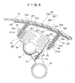
- an airbag apparatus 20 for a vehicle includes an interior panel 22, an airbag 24, an airbag case 26, a frame 28, a pair of reinforcement members 30, an inflator (not shown), etc.
- the interior panel 22 is attached in front of the front passenger seat of the automobile and is formed of a synthetic resin material, such as polypropylene, such that the interior panel 22 has a three-dimensional curved surface.
- the frame 28 holds the airbag case 26 and the reinforcement members 30 on the reverse surface side of the interior panel 22.
- the frame 28 is formed of a highly elastic, polypropylene-based resin material containing a reinforcing material such as talc and glass fibre in an amount of 10 to 30% by weight, and assumes the form of a rectangular tubule having a transverse cross-sectional area required to inflate and deploy the airbag 24.
- the frame 28 has a rectangular opening 28a having the same transverse cross-sectional area.
- a joint flange 281 is integrally formed at the upper end of the frame 28 where the opening 28a is provided, and extends outwardly perpendicular to the frame 28. The flange 281 is bonded, by means of vibration welding or any other suitable process, to the reverse surface of the interior panel 22, whereby the frame 28 is fixed to the interior panel 22.
- hinge motion restricting portions (hinge motion restricting members) 32a and 32b are formed along the entirety of the opposite longer sides of the rectangular opening 28a of the frame 28 in such a manner that the hinge motion restricting portions 32a and 32b project toward the longitudinal centreline (or a central area) of the opening 28a over a predetermined distance.
- a rectangular portion of the interior panel 22 facing the rectangular opening 28a of the frame 28 serves as a fracture-opening section 34 for allowing the airbag 24 to inflate and deploy through the interior panel 22.
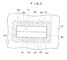
- a fracture groove 36 is formed on the reverse surface of the interior panel 22 to be located within the fracture-opening section 34 so as to form an opening 48 (see Figure 6) when the airbag apparatus is operated, thereby to enable the airbag 24 to inflate and deploy to the outside of the interior panel 22 through the opening 48.
- the fracture groove 36 is composed of side fracture groove sections 36a and 36b which are formed on the reverse surface of the fracture-opening section 34 to face the shorter sides of the rectangular opening 28a; hinge-side fracture groove sections 36c and 36d which are formed on the reverse surface of the fracture-opening section 34 at locations corresponding to the ends of the hinge motion restricting portions 32a and 32b or locations offset from the ends of the hinge motion restricting portions 32a and 32b toward the longitudinal centreline of the opening 28a; and a centre fracture groove section 36e which is formed on the reverse surface of the fracture-opening section 34 to connect the side fracture groove sections 36a and 36b.
- the fracture-opening section 34 is divided into two fracture-opening subsections 34a and 34b, surrounded by the side fracture groove sections 36a and 36b, the hinge-side fracture groove sections 36c and 36d, and the centre fracture groove section 36e.
- the fracture-opening subsections 34a and 34b are separated from the interior panel 22, and are opened in the manner of a casement, while being turned about hinge portions 303 of the reinforcement members 30, whereby the hinge portions 303 come into engagement with the hinge motion restricting portions 32a and 32b.
- the paired reinforcement members 30, which reinforce the fracture-opening section 34 from the reverse side thereof, are formed of a synthetic resin such as polypropylene (PP) or thermoplastic polyolefin (TPO).
- PP polypropylene
- TPO thermoplastic polyolefin
- Each of the reinforcement members 30 includes a support portion 301 coupled with the inner wall surface of the frame 28 via a dovetail; a reinforcement portion 302 bonded, by means of vibration welding or any other suitable process, to the reverse surfaces of the fracture-opening subsections 34a and 34b, which are ruptured along the side fracture groove sections 36a and 36b, the hinge-side fracture groove sections 36c and 36d, and the centre fracture groove section 36e; and the hinge portion 303 which faces the hinge motion restricting portion 32a or 32b and which connects the support portion 301 and the reinforcement portion 302 in a bendable manner.
- the centre fracture groove section 36e is offset from the boundary between the two fracture-opening subsections 34a and 34b toward the fracture-opening subsection 34b, so that the area of the fracture-opening subsection 34a becomes greater than that of the fracture-opening subsection 34b.
- the fracture groove sections 36a to 36e are formed by forming successive small holes (blind holes) on the reverse surface of the interior panel 22 through irradiation with an infrared laser beam having a beam diameter of 0.2 to 0.5 mm and a wavelength of 10.6 ⁇ m, in such a manner that the small holes do not pass completely through the interior panel 22.
- the airbag 24 is accommodated within the airbag case 26 formed from a metal plate in a folded condition as shown in Figure 4.
- a plurality of hooks 38 are provided on the side wall portions of the airbag case 26 in the vicinity of an upper end opening 26a thereof such that they project outward.
- the hooks 38 are engaged with holes 301a formed in the support portions 301 of the reinforcement members 30 and holes 28b formed in the frame 28 to correspond to the holes 301a, whereby the airbag case 26 is secured to the frame 28.
- An inflator accommodation portion 40 is provided at the lower end of the airbag case 26 so as to accommodate an inflator (not shown) for supplying an inflation gas to the airbag 24.
- the airbag case 26 is fixed to a stationary member, such as a cross-member 44, via a support member 42 and by means of a bolt and nut 46.
- the thus-configured airbag apparatus 20 of the first embodiment functions in the following manner.
- a control unit including a CPU judges whether or not the detected impact force is equal to or greater than a predetermined value.
- the control unit judges that the impact force is equal to or greater than the predetermined value, the control unit issues a signal for causing the inflator to generate a high-pressure gas.
- the gas is fed to the airbag 24 so as to promptly inflate the airbag 24.
- the inflating airbag 24 presses, from inside, the fracture-opening section 34 surrounded by the fracture groove sections 36a to 36d.
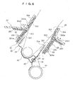
- the centre fracture groove section 36e, the side fracture groove sections 36a and 36b, and the hinge-side fracture groove sections 36c and 36d of the fracture-opening section 34 are fractured, whereby the fracture-opening section 34 surrounded by the fracture groove sections 36a to 36d is divided into the two fracture-opening subsections 34a and 34b.
- the fracture-opening subsections 34a and 34b are separated from the interior panel 22, and are opened in the manner of a casement as shown in Figure 6, while being turned about hinge portions 303 of the reinforcement members 30, whereby the hinge portions 303 come into engagement with the hinge motion restricting portions 32a and 32b.
- the airbag 24 inflates and deploys to the outside of the interior panel 22 via the opening 48, which is formed through opening of the fracture-opening subsections 34a and 34b in the manner of a casement.
- the inflated airbag 24 supports the passenger at his/her chest or head, thereby protecting the passenger from the impact force of collision.
- the hinge motion restricting portions 32a and 32b are formed along the entirety of the opposite longer sides of the rectangular opening 28a of the frame 28 in such a manner that the hinge motion restricting portions 32a and 32b project toward the longitudinal centreline of the opening 28a.
- the fracture groove 36 which enables the airbag 24 to inflate and deploy toward the outside the interior panel 22 via the fracture-opening section 34 of the interior panel 22, includes the side fracture groove sections 36a and 36b, the hinge-side fracture groove sections 36c and 36d and the centre fracture groove section 36e.
- the fracture-opening section 34 is divided into the two fracture-opening subsections 34a and 34b, surrounded by the side fracture groove sections 36a and 36b, the hinge-side fracture groove sections 36c and 36d and the centre fracture groove section 36e, whereby the fracture-opening subsections 34a and 34b, separated from the interior panel 22, are opened in the manner of a casement, while being turned about hinge portions 303 of the reinforcement members 30, and the hinge portions 303 are brought into engagement with the hinge motion restricting portions 32a and 32b.
- the hinge-side fracture groove sections 36c and 36d of the fracture-opening section 34 are formed at locations corresponding to the ends of the hinge motion restricting portions 32a and 32b or locations offset from the ends of the hinge motion restricting portions 32a and 32b toward the longitudinal centreline of the opening 28a. Therefore, as shown in Figure 6, a distance L3 between the hinge-side rupture edge 34a1 of the fracture-opening subsection 34a and a welding rib 302a of the corresponding reinforcement portion 302 and a distance L4 between the hinge-side rupture edge 34b1 of the fracture-opening subsection 34b and a welding rib 302a of the corresponding reinforcement portion 302 can be shortened as compared with those in conventional airbag apparatuses. Therefore, the fracture-opening subsections 34a and 34b, which have been separated as a result of rupture of the fracture groove 36, can be smoothly opened in opposite directions without causing interference with the interior panel 22, and deployment of the airbag can be facilitated.
- the centre fracture groove section 36e is offset from the boundary between the two fracture-opening subsections 34a and 34b toward the fracture-opening subsection 34b, so that the area of the fracture-opening subsection 34a becomes greater than that of the fracture-opening subsection 34b.
- the second embodiment differs from the first embodiment in that the interior panel 22 has a three-layer structure; i.e., includes a substrate 221 formed of hard polypropylene (PP) and having a thickness of 3 mm to 4 mm; a foam layer 222 layered over and bonded to the surface of the substrate 221, formed of foamed polypropylene, and having a thickness of 1.5 mm to 2 mm; and a surface layer 223 layered over and bonded to the surface of the foam layer 222, formed of thermoplastic polyolefin (TPO), and having a thickness of 0.6 mm to 1 mm.
- PP hard polypropylene
- TPO thermoplastic polyolefin
- the side fracture groove sections 36a and 36b, the hinge-side fracture groove sections 36c and 36d, and the centre fracture groove section 36e are formed by forming small holes (blind holes), by means of a laser beam, on the reverse surface of the interior panel 22 in such a manner that the small holes do not pass completely through the substrate 221.
- a control unit including a CPU judges whether or not the detected impact force is equal to or greater than a predetermined value.
- the control unit judges that the impact force is equal to or greater than the predetermined value, the control unit issues a signal for causing the inflator to generate a high-pressure gas.
- the gas is fed to the airbag 24 so as to promptly inflate the airbag 24.
- the inflating airbag 24 presses, from inside, the fracture-opening section 34 of the substrate 221 surrounded by the fracture groove 36.
- the centre fracture groove section 36e, the side fracture groove sections 36a and 36b, and the hinge-side fracture groove sections 36c and 36d of the fracture-opening section 34 are fractured, whereby the fracture-opening section 34 surrounded by the fracture groove sections 36a to 36d is divided into two fracture-opening subsections 34a and 34b.
- the fracture-opening subsections 34a and 34b are separated from the substrate 221.
- the rupture edges of the fracture-opening subsections 34a and 34b cut the surface layer 223 along lines corresponding to the centre fracture groove section 36e and the side fracture groove sections 36a and 36b. In this case, the surface layer 223 is not cut along lines corresponding to the hinge-side fracture groove sections 36c and 36d.
- the fracture-opening subsections 34a and 34b are opened in the manner of a casement as shown in Figure 6, while being turned about hinge portions 303 of the reinforcement members 30, whereby the hinge portions 303 come into engagement with the hinge motion restricting portions 32a and 32b.
- the airbag 24 inflates and deploys to the outside of the interior panel 22 via the opening 48, which is formed through opening of the fracture-opening subsections 34a and 34b in the manner of a casement.
- the inflated airbag 24 supports the passenger at his/her chest or head, thereby protecting the passenger from the impact force of collision.
- the airbag apparatus according to the second embodiment achieves action and effects similar to those attained by the first embodiment.
- the fracture groove 36 is formed by means of laser cutting.
- the present invention is not limited thereto, and can be applied to airbag apparatuses in which continuous or intermittent grooves or like depressions are formed on the reverse surface of the interior panel 22 by use of a cutting tool or the like.
- the method of bonding the frame 28 and the reinforcement members 30 to the reverse surface of the interior panel 22 is not limited to vibration welding, and adhesive may be used to bond the frame 28 and the reinforcement members 30 to the reverse surface of the interior panel 22.
- the invention provides an airbag apparatus in which, when the airbag inflates, a fracture-opening section of an interior panel is ruptured and divided into two fracture-opening subsections, which are turned outward about hinge portions of reinforcement members in the manner of a casement, with hinge motion restricting members being provided on a frame such that, when the fracture-opening subsections are turned, the hinge motion restricting members come into engagement with the hinge portions.
Landscapes
- Engineering & Computer Science (AREA)
- Mechanical Engineering (AREA)
- Air Bags (AREA)
Applications Claiming Priority (1)
| Application Number | Priority Date | Filing Date | Title |
|---|---|---|---|
| JP2005160250A JP4838539B2 (ja) | 2005-05-31 | 2005-05-31 | 車両用エアーバック装置 |
Publications (2)
| Publication Number | Publication Date |
|---|---|
| EP1728691A2 true EP1728691A2 (fr) | 2006-12-06 |
| EP1728691A3 EP1728691A3 (fr) | 2008-01-30 |
Family
ID=36928628
Family Applications (1)
| Application Number | Title | Priority Date | Filing Date |
|---|---|---|---|
| EP06114763A Withdrawn EP1728691A3 (fr) | 2005-05-31 | 2006-05-31 | Dispositif d'airbag pour véhicule |
Country Status (3)
| Country | Link |
|---|---|
| US (1) | US7354061B2 (fr) |
| EP (1) | EP1728691A3 (fr) |
| JP (1) | JP4838539B2 (fr) |
Cited By (4)
| Publication number | Priority date | Publication date | Assignee | Title |
|---|---|---|---|---|
| FR2913387A1 (fr) * | 2007-03-06 | 2008-09-12 | Renault Sas | Assemblage de fixation d'un module de coussin de securite sur une structure mecaniquement resistante de la planche de bord. |
| EP2080675A1 (fr) * | 2008-01-18 | 2009-07-22 | Takata Corporation | Couvercle d'airbag, panneau d'instrument, dispositif d'airbag, et stockage d'airbag |
| WO2015183918A3 (fr) * | 2014-05-27 | 2016-02-25 | Johnson Controls Technology Company | Panneau intérieur de véhicule et procédé de fabrication |
| WO2019134796A1 (fr) * | 2018-01-08 | 2019-07-11 | Volkswagen Aktiengesellschaft | Recouvrement d'habitacle servant à recevoir un coussin de sécurité servant à protéger un passager dans une cabine de conducteur d'un véhicule automobile |
Families Citing this family (18)
| Publication number | Priority date | Publication date | Assignee | Title |
|---|---|---|---|---|
| DE10345026B4 (de) * | 2003-09-24 | 2007-07-19 | Faurecia Innenraum Systeme Gmbh | Innenverkleidungsteil zur Abdeckung eines Airbags |
| JP4843371B2 (ja) * | 2006-05-09 | 2011-12-21 | 本田技研工業株式会社 | エアバッグ装置 |
| JP4843442B2 (ja) * | 2006-10-02 | 2011-12-21 | 本田技研工業株式会社 | エアバッグ装置 |
| JP4842095B2 (ja) * | 2006-11-06 | 2011-12-21 | タカタ株式会社 | エアバッグカバー、インストルメントパネル、エアバッグ装置 |
| DE102007005922B4 (de) * | 2007-02-06 | 2010-11-18 | Lisa Dräxlmaier GmbH | Richtungsgeber für die Entfaltung eines Airbags |
| US7891702B2 (en) * | 2008-03-27 | 2011-02-22 | Intertec Systems, Llc | Apparatus and method for attaching passenger side inflatable restraint chute |
| JP5190292B2 (ja) * | 2008-04-18 | 2013-04-24 | 三光合成株式会社 | 車両用エアーバック装置 |
| KR101071733B1 (ko) * | 2008-12-01 | 2011-10-11 | 기아자동차주식회사 | 차량용 에어백장치 |
| KR101113667B1 (ko) * | 2008-12-04 | 2012-02-14 | 기아자동차주식회사 | 차량의 에어백 장착용 크래쉬패드 |
| JP5191054B2 (ja) * | 2009-01-09 | 2013-04-24 | 日本プラスト株式会社 | エアバッグ装置のカバー体及びエアバッグ装置 |
| CN102939224A (zh) * | 2010-05-11 | 2013-02-20 | 江森自控科技公司 | 车辆内部组件 |
| US8251435B2 (en) * | 2010-07-19 | 2012-08-28 | Inoac Corporation | Spoiler |
| EP2543553B1 (fr) * | 2011-07-07 | 2015-03-04 | Zodiac Seats France | Absorbeur d'énergie pneumatique et mécanique |
| FR3007346B1 (fr) * | 2013-06-24 | 2016-11-04 | Visteon Global Tech Inc | Dispositif de fermeture de logement pour airbag |
| WO2015025630A1 (fr) * | 2013-08-23 | 2015-02-26 | 本田技研工業株式会社 | Dispositif de coussin de sécurité gonflable |
| HUE056064T2 (hu) * | 2018-01-22 | 2022-01-28 | Motherson Innovations Co Ltd | Légzsákvezetõ berendezés egy gépjármû egy légzsákjának vezetésére, légzsák egység, ami tartalmaz egy ilyen légzsákvezetõ berendezést, valamint belsõ burkoló elem és eljárás egy ilyen belsõ burkoló elem elõállítására, ami tartalmaz egy ilyen légzsákvezet.. |
| JP7059913B2 (ja) * | 2018-12-10 | 2022-04-26 | トヨタ自動車株式会社 | エアバッグ装置 |
| FR3096630B1 (fr) * | 2019-05-29 | 2021-06-18 | Renault Sas | Véhicule doté de volets d’airbag passager allégés |
Citations (5)
| Publication number | Priority date | Publication date | Assignee | Title |
|---|---|---|---|---|
| DE4137926C2 (de) | 1990-11-19 | 1997-11-27 | Toyota Motor Co Ltd | Abdeckung für ein Airbagmodul in einem Kraftfahrzeug |
| WO1999001317A1 (fr) | 1997-07-03 | 1999-01-14 | Sanko Gosei Uk Ltd. | Couvercle d'airbag |
| EP1348601A2 (fr) | 2002-03-28 | 2003-10-01 | Sanko Gosei Kabushiki Kaisha | Dispositif d'airbag pour automobile |
| EP1388467A1 (fr) | 2002-08-06 | 2004-02-11 | Sanko Gosei Kabushiki Kaisha | Dispositif d'airbag pour automobile |
| JP2004114919A (ja) | 2002-09-27 | 2004-04-15 | Sanko Gosei Ltd | 自動車用エアーバッグ装置における破断開放部の改良 |
Family Cites Families (14)
| Publication number | Priority date | Publication date | Assignee | Title |
|---|---|---|---|---|
| GB2287226B (en) * | 1994-03-10 | 1997-05-14 | Autoliv Dev | Improvements in or relating to an air-bag arrangement |
| JP3417295B2 (ja) * | 1998-04-28 | 2003-06-16 | トヨタ自動車株式会社 | エアバッグドア部を有する車両用内装部材 |
| JP2001088646A (ja) | 1999-09-22 | 2001-04-03 | Mitsuboshi Belting Ltd | エアバッグドア構造 |
| US6761375B2 (en) | 2000-04-26 | 2004-07-13 | Sanko Gosei Kabushiki Kaisha | Structure of reinforcement plate member used in automobile airbag apparatus |
| JP2002029356A (ja) * | 2000-05-12 | 2002-01-29 | Sanko Gosei Ltd | 助手席用エアーバッグ装置 |
| JP2002160601A (ja) * | 2000-11-28 | 2002-06-04 | Inoac Corp | ドア補強部材 |
| US6692017B2 (en) | 2000-12-25 | 2004-02-17 | Daihatsu Motor Co., Ltd. | Airbag apparatus for automobile |
| JP4085308B2 (ja) * | 2002-05-29 | 2008-05-14 | 株式会社イノアックコーポレーション | エアバッグドアの開放構造 |
| JP2004155212A (ja) * | 2002-11-01 | 2004-06-03 | Nishikawa Kasei Co Ltd | エアバッグドア部を有する車両用内装部材 |
| JP2005007984A (ja) * | 2003-06-18 | 2005-01-13 | Nishikawa Kasei Co Ltd | エアバッグドア部付内装品 |
| JP4426813B2 (ja) * | 2003-10-10 | 2010-03-03 | 三光合成株式会社 | 自動車用エアーバッグ装置 |
| JP2005206142A (ja) * | 2003-12-24 | 2005-08-04 | Takata Corp | エアバッグ装置 |
| JP4382518B2 (ja) * | 2004-02-19 | 2009-12-16 | 三光合成株式会社 | 自動車用エアーバッグ装置 |
| US7275759B2 (en) * | 2005-03-08 | 2007-10-02 | Takata Corporation | Cover for use in airbag apparatus, and airbag apparatus |
-
2005
- 2005-05-31 JP JP2005160250A patent/JP4838539B2/ja not_active Expired - Lifetime
-
2006
- 2006-05-25 US US11/442,023 patent/US7354061B2/en active Active
- 2006-05-31 EP EP06114763A patent/EP1728691A3/fr not_active Withdrawn
Patent Citations (5)
| Publication number | Priority date | Publication date | Assignee | Title |
|---|---|---|---|---|
| DE4137926C2 (de) | 1990-11-19 | 1997-11-27 | Toyota Motor Co Ltd | Abdeckung für ein Airbagmodul in einem Kraftfahrzeug |
| WO1999001317A1 (fr) | 1997-07-03 | 1999-01-14 | Sanko Gosei Uk Ltd. | Couvercle d'airbag |
| EP1348601A2 (fr) | 2002-03-28 | 2003-10-01 | Sanko Gosei Kabushiki Kaisha | Dispositif d'airbag pour automobile |
| EP1388467A1 (fr) | 2002-08-06 | 2004-02-11 | Sanko Gosei Kabushiki Kaisha | Dispositif d'airbag pour automobile |
| JP2004114919A (ja) | 2002-09-27 | 2004-04-15 | Sanko Gosei Ltd | 自動車用エアーバッグ装置における破断開放部の改良 |
Cited By (7)
| Publication number | Priority date | Publication date | Assignee | Title |
|---|---|---|---|---|
| FR2913387A1 (fr) * | 2007-03-06 | 2008-09-12 | Renault Sas | Assemblage de fixation d'un module de coussin de securite sur une structure mecaniquement resistante de la planche de bord. |
| WO2008113960A3 (fr) * | 2007-03-06 | 2008-11-06 | Renault Sa | Assemblage de fixation d'un module de coussin de securite sur une structure mecaniquement resistante de la planche de bord |
| EP2080675A1 (fr) * | 2008-01-18 | 2009-07-22 | Takata Corporation | Couvercle d'airbag, panneau d'instrument, dispositif d'airbag, et stockage d'airbag |
| US7934745B2 (en) | 2008-01-18 | 2011-05-03 | Takata Corporation | Airbag cover, instrument panel, airbag device, and airbag storage |
| CN101486338B (zh) * | 2008-01-18 | 2013-07-17 | 高田株式会社 | 气囊罩、仪表板、气囊装置、气囊收容体 |
| WO2015183918A3 (fr) * | 2014-05-27 | 2016-02-25 | Johnson Controls Technology Company | Panneau intérieur de véhicule et procédé de fabrication |
| WO2019134796A1 (fr) * | 2018-01-08 | 2019-07-11 | Volkswagen Aktiengesellschaft | Recouvrement d'habitacle servant à recevoir un coussin de sécurité servant à protéger un passager dans une cabine de conducteur d'un véhicule automobile |
Also Published As
| Publication number | Publication date |
|---|---|
| JP4838539B2 (ja) | 2011-12-14 |
| US7354061B2 (en) | 2008-04-08 |
| EP1728691A3 (fr) | 2008-01-30 |
| US20060267313A1 (en) | 2006-11-30 |
| JP2006335152A (ja) | 2006-12-14 |
Similar Documents
| Publication | Publication Date | Title |
|---|---|---|
| EP1728691A2 (fr) | Dispositif d'airbag pour véhicule | |
| EP1738970B1 (fr) | Dispositif d'airbag pour véhicule et couvercle d'airbag | |
| US7165782B2 (en) | Airbag apparatus for automobile | |
| EP1348601B1 (fr) | Dispositif d'airbag pour automobile | |
| US7168731B2 (en) | Airbag apparatus for automobile | |
| JP2001502996A (ja) | エアバッグカバー | |
| KR20000048597A (ko) | 은폐식 에어백 커버의 전방 취약부 구조 | |
| US20060202446A1 (en) | Airbag module | |
| US6460876B1 (en) | Vehicular air-bag lid structure | |
| JP2921996B2 (ja) | 車体側部のエネルギ吸収構造 | |
| JP2003146172A (ja) | 自動車用エアーバッグ装置の破断開口部構造 | |
| JP4296040B2 (ja) | 自動車用エアーバッグ装置の開口部構造 | |
| JP2007283865A (ja) | 車両のパネル部材、該パネル部材を用いた車両のインストルメントパネル、およびエアバックドアの製造方法 | |
| JP2007216873A (ja) | 車両用エアーバッグ装置及びエアーバッグカバ− | |
| JP2009248610A (ja) | エアバッグドア支持構造 | |
| JP4426878B2 (ja) | 自動車用エアーバッグ装置 | |
| JP2006327578A (ja) | 側方に開口するエアバッグドア付きエアバッグモジュールカバー | |
| KR20150139740A (ko) | 에어백 모듈 | |
| JP2005271652A (ja) | 自動車用エアーバッグ装置 | |
| KR101360340B1 (ko) | 차량의 커튼에어백 | |
| BR102024014933A2 (pt) | Forro de painel para airbag de teto e veículo | |
| JP2005238917A (ja) | エアバッグカバー | |
| JP2006298311A (ja) | 車両用エアーバック装置及びエアーバックカバー | |
| JP2005059723A (ja) | 自動車用エアーバッグ装置 | |
| JPH10129386A (ja) | エアバッグドア部を一体に有するインストルメントパ ネル |
Legal Events
| Date | Code | Title | Description |
|---|---|---|---|
| PUAI | Public reference made under article 153(3) epc to a published international application that has entered the european phase |
Free format text: ORIGINAL CODE: 0009012 |
|
| AK | Designated contracting states |
Kind code of ref document: A2 Designated state(s): AT BE BG CH CY CZ DE DK EE ES FI FR GB GR HU IE IS IT LI LT LU LV MC NL PL PT RO SE SI SK TR |
|
| AX | Request for extension of the european patent |
Extension state: AL BA HR MK YU |
|
| PUAL | Search report despatched |
Free format text: ORIGINAL CODE: 0009013 |
|
| AK | Designated contracting states |
Kind code of ref document: A3 Designated state(s): AT BE BG CH CY CZ DE DK EE ES FI FR GB GR HU IE IS IT LI LT LU LV MC NL PL PT RO SE SI SK TR |
|
| AX | Request for extension of the european patent |
Extension state: AL BA HR MK YU |
|
| 17P | Request for examination filed |
Effective date: 20080730 |
|
| AKX | Designation fees paid |
Designated state(s): DE FR GB NL |
|
| 17Q | First examination report despatched |
Effective date: 20081006 |
|
| STAA | Information on the status of an ep patent application or granted ep patent |
Free format text: STATUS: THE APPLICATION IS DEEMED TO BE WITHDRAWN |
|
| 18D | Application deemed to be withdrawn |
Effective date: 20091218 |