EP1729367A1 - Gefaltete antenne - Google Patents
Gefaltete antenne Download PDFInfo
- Publication number
- EP1729367A1 EP1729367A1 EP05726669A EP05726669A EP1729367A1 EP 1729367 A1 EP1729367 A1 EP 1729367A1 EP 05726669 A EP05726669 A EP 05726669A EP 05726669 A EP05726669 A EP 05726669A EP 1729367 A1 EP1729367 A1 EP 1729367A1
- Authority
- EP
- European Patent Office
- Prior art keywords
- segments
- face
- antenna
- conductor film
- antenna element
- Prior art date
- Legal status (The legal status is an assumption and is not a legal conclusion. Google has not performed a legal analysis and makes no representation as to the accuracy of the status listed.)
- Withdrawn
Links
Images



Classifications
-
- H—ELECTRICITY
- H01—ELECTRIC ELEMENTS
- H01Q—ANTENNAS, i.e. RADIO AERIALS
- H01Q1/00—Details of, or arrangements associated with, antennas
- H01Q1/36—Structural form of radiating elements, e.g. cone, spiral, umbrella; Particular materials used therewith
- H01Q1/38—Structural form of radiating elements, e.g. cone, spiral, umbrella; Particular materials used therewith formed by a conductive layer on an insulating support
-
- H—ELECTRICITY
- H01—ELECTRIC ELEMENTS
- H01Q—ANTENNAS, i.e. RADIO AERIALS
- H01Q1/00—Details of, or arrangements associated with, antennas
- H01Q1/12—Supports; Mounting means
- H01Q1/22—Supports; Mounting means by structural association with other equipment or articles
- H01Q1/2283—Supports; Mounting means by structural association with other equipment or articles mounted in or on the surface of a semiconductor substrate as a chip-type antenna or integrated with other components into an IC package
-
- H—ELECTRICITY
- H01—ELECTRIC ELEMENTS
- H01Q—ANTENNAS, i.e. RADIO AERIALS
- H01Q1/00—Details of, or arrangements associated with, antennas
- H01Q1/36—Structural form of radiating elements, e.g. cone, spiral, umbrella; Particular materials used therewith
-
- H—ELECTRICITY
- H01—ELECTRIC ELEMENTS
- H01Q—ANTENNAS, i.e. RADIO AERIALS
- H01Q13/00—Waveguide horns or mouths; Slot antennas; Leaky-waveguide antennas; Equivalent structures causing radiation along the transmission path of a guided wave
- H01Q13/20—Non-resonant leaky-waveguide or transmission-line antennas; Equivalent structures causing radiation along the transmission path of a guided wave
- H01Q13/206—Microstrip transmission line antennas
-
- H—ELECTRICITY
- H01—ELECTRIC ELEMENTS
- H01Q—ANTENNAS, i.e. RADIO AERIALS
- H01Q5/00—Arrangements for simultaneous operation of antennas on two or more different wavebands, e.g. dual-band or multi-band arrangements
-
- H—ELECTRICITY
- H01—ELECTRIC ELEMENTS
- H01Q—ANTENNAS, i.e. RADIO AERIALS
- H01Q5/00—Arrangements for simultaneous operation of antennas on two or more different wavebands, e.g. dual-band or multi-band arrangements
- H01Q5/30—Arrangements for providing operation on different wavebands
- H01Q5/307—Individual or coupled radiating elements, each element being fed in an unspecified way
- H01Q5/342—Individual or coupled radiating elements, each element being fed in an unspecified way for different propagation modes
- H01Q5/357—Individual or coupled radiating elements, each element being fed in an unspecified way for different propagation modes using a single feed point
-
- H—ELECTRICITY
- H01—ELECTRIC ELEMENTS
- H01Q—ANTENNAS, i.e. RADIO AERIALS
- H01Q9/00—Electrically-short antennas having dimensions not more than twice the operating wavelength and consisting of conductive active radiating elements
- H01Q9/04—Resonant antennas
- H01Q9/30—Resonant antennas with feed to end of elongated active element, e.g. unipole
- H01Q9/42—Resonant antennas with feed to end of elongated active element, e.g. unipole with folded element, the folded parts being spaced apart a small fraction of the operating wavelength
Definitions
- the present invention relates to an antenna suitable for use in, for example, wireless LANs (Local Area Networks) or the like, which can transmit and receive signals of two or more frequency bands, each of which has a wide bandwidth, a small size and a high function. More particularly, the present invention relates to a small-sized antenna which can operate at two frequency bands of, for example, 2.4 GHz and 5 GHz, and which still has a bandwidth of approximately 1 GHz at the frequency band of 5 GHz.
- wireless LANs Local Area Networks
- a folded antenna 50 for example, shown in Fig. 10 has been introduced as an antenna suitable for transmitting and receiving signals of two or more frequency bands having approximately two times relationship (for example, cf. PATENT DOCUMENT 1).
- the folded antenna 50 it is known that resonance at two or more frequency bands having approximately two times relationship can be achieved, since resonance frequencies can be adjusted by arranging intervals between adjacent segments 51, or the like.
- the antenna of this kind is formed on a surface of a cylindrical base made of, for example, dielectric materials or the like, mounted on a top part of a casing as an antenna for a portable telephone or the like, and used by setting the antenna element 51 located through a certain distance h to a ground face (a ground plate) 52 which is the casing of the portable telephone or the like.
- PATENT DOCUMENT 1 Japanese Patent Application Laid-Open No. HEI10-13135
- present wireless LANs require an antenna resonating at two frequency bands of 2.4 GHz and 5 GHz, and having a bandwidth of 100 MHz at the frequency of 2.4 GHz and a bandwidth of approximately 1 GHz at the frequency of 5 GHz, operating from 5 to 6 GHz.
- the present invention is directed to solve the above-described problems and an object of the present invention is to provide a folded antenna to resonate at two or more frequency bands, for example such as 2.4 GHz and 5 GHz, and to widen a bandwidth to approximately 1 GHz, for example from 5 GHz to 6 GHz, only by a single antenna.
- Another object of the present invention is to provide a folded antenna of a structure in which a desired impedance or a desired resonance frequency can be obtained only by adjusting turning parts, widths of segments and intervals between segments, with less influence caused by a relationship to the ground plate in adjusting the impedance.
- the present inventors have studied earnestly to develop an antenna, for use in present wireless LANs as described above, which can be used at two frequency bands of 2.4 GHz and 5 GHz which has a bandwidth from 5 to 6 GHz.
- the antenna which satisfies the above-described conditions required in the wireless LANs, has been consequently realized, by a structure where an antenna element is turned back in a direction parallel to one face of a ground plate (a direction perpendicular to a direction in which the antenna element mainly extends), or in a direction parallel to a ground conductor film (the ground plate) which is perpendicular to the antenna element on a side of a feeding part, and the lengths of the segments parallel to the ground conductor film increase as the segments are away from the feeding part, wherein resonance frequencies can be adjusted by arranging the lengths of the segments between each turning part and intervals between adjacent segments, resonance can be nearly obtained in a range between the two resonance frequencies by setting them closely each other in high resonance frequencies, and a wide bandwidth of approximately 1
- a folded antenna according to the present invention includes; a ground plate, and an antenna element having a plurality of turning parts and a plurality of segments formed between the turning parts, the segments being formed by being turned back in zigzag in parallel to one face of the ground plate at the turning parts, while the antenna element extending perpendicularly to the one face of the ground plate, wherein a length of one segment or a length of a set of segments, which is a pair of arbitrary two adjacent segments having the same length, is shorter on a side of the one face of the ground plate and increase gradually as the segment or the set of segments is away from the one face of the ground plate, and wherein the antenna element is formed such that the folded antenna resonates at two or more frequency bands and has a fractional bandwidth of 4% or more of a frequency in a first frequency band and a fractional bandwidth of 15% or more of a frequency in a second frequency band, by adjusting lengths of the segments or sets of segments having the same length, and intervals between adjacent segments.
- the fractional bandwidth means
- the one face of the ground plate means a principal face or an end face of the ground plate, nearest a feeding part of the antenna, for example a face in a direction of a thickness of the ground conductor film at an end part of the ground conductor film nearest the feeding part of the antenna element in case that the antenna element and the ground plate (the ground conductor film) are formed of a conductor film, side by side, on a surface of a dielectric substrate.
- the folded antenna according to the present invention may further include: a dielectric base, on a dielectric face, that is, a surface or an inside face of which the antenna element is formed by a conductor film; a ground conductor film to be connected to ground as the one face of the ground plate, the ground conductor film being provided on a side surface of the dielectric base which is perpendicular to the dielectric face; and an end part of the antenna element which is provided on the side surface so as not to contact to the ground conductor film; wherein the antenna element is extended in a direction perpendicular to the side surface from the end part on the dielectric face, and then turned so as to be in parallel to one side which is a cross line of the side surface and the dielectric face, and this construction is repeated such that a plurality of turning parts are formed in a direction away from the side surface.
- a distance between a first segment, which is nearest the ground conductor film among segments parallel to the one side, and the ground conductor film is from 0.8 to 1 mm
- a length of the first segment is from 4 to 4.5 mm
- the lengths of the segments are set so as to increase gradually as the segments are away from the ground conductor film, by a ratio from 1.05 to 2, which is a ratio of the length of adjacent segments or adjacent a segment and a set of segments parallel to the one side surface.
- the turning parts may be formed so as to spread symmetrically at a same angle for both sides of the center line which is defined as an extension of the end part of the antenna element perpendicularly to the one face of the ground plate, or the turning parts of one side are formed on the center line or a line apart from the center line by a certain distance and parallel to it and the turning parts of another side are formed to spread to only one direction as to the center line, in order.
- ground conductor film By forming the ground conductor film so as to extend to the dielectric face of the dielectric base, for example, influence by other parts located on a circuit board or by users hand of portable telephones can be reduced.
- the structure according to the present invention gives a small influence to an input impedance of the antenna because of a small capacitance between the ground plate and the antenna element, since the segments of the antenna element are short near the ground plate, and increase in length as the segments are away from the ground plate. And as explained later, since a resonance frequency can be adjusted by changing the lengths of the segments in order, a low frequency band can be set closely to a desired frequency, and, simultaneously, two resonance frequencies in high frequency can also be set very near, and the range between two resonance frequencies can be treated as one resonance in a high frequency band.
- the impedance can be prevented from lowering related to the ground plate, and an antenna which resonates at a desired frequency band with a desired bandwidth can be realized.
- the folded antenna according to the present invention includes a ground plate 2 and an antenna element 1 having a plurality of turning parts 13, 15, 17 and a plurality of segments (a first segment 12, a set of a second segment 14 and a third segment 16, and a forth segment 18) formed between the turning parts.
- the segments are formed by turning back the antenna element in zigzag in parallel to one face of the ground plate 2 at the turning parts, while the antenna element generally extending perpendicularly to the one face of the ground plate 2.
- a length of one segment or a length of a set of segments which is a pair of arbitrary two adjacent segments having the same length, is shorter on a side of the one face of the ground plate 2 (feeding part 4) and increase gradually as the segment or the set of segments is away from the one face of the ground plate 2.
- two adjacent segments 14 and 16 of the same length are treated as one set of segments combined in one pair.
- the antenna element is formed such that the folded antenna resonates at two or more frequency bands and has a fractional bandwidth of 4% or more of a frequency in a first frequency band and a fractional bandwidth of 15% or more of a frequency in a second frequency band, by adjusting each of lengths L 1 , L 2 and L 3 of the segments 12, 14, 16 and 18, and intervals d 1 , d 2 and d 3 between adjacent segments.
- FIG. 1 An example shown in Fig. 1 is an antenna for wireless LANs used at two frequency bands of 2.4 to 2.5 GHz and of 5 to 6 GHz, in which the antenna element 1 is formed on a surface of a dielectric base 3 made of ceramic having a relative dielectric constant of 20 having a size represented as length(M) ⁇ width(W) ⁇ thickness(t) are 7 mm ⁇ 8mm ⁇ 0.9mm.
- the antenna element 1 is formed on the surface of the dielectric base 3 as shown in Fig.
- the point is to turn back the antenna element in order to obtain a desired bandwidth at a desired frequency band, in such manner that the antenna element 1 is turned back plural times in a direction parallel to the one face of the ground plate 2 (a direction perpendicular to a direction in which the antenna element generally extends), and that the length of the segment parallel to the ground plate 2 increases as the segment is away from the ground plate 2.
- the antenna element 1 can be formed by patterning a conductor film formed on a ceramic substrate or the like by sputtering technique as described above, by forming a desired pattern by screen printing technique, or by folding metal wire like cable materials.
- the antenna element 1 is characterized in that the lengths L 1 , L 2 , L 3 of the segments between the turning parts are shorter on the side of the ground conductor film 2 of the ground plate and increase as the segments are away from, and that the antenna can be used at 2.4 to 2.5 GHz and 5 to 6 GHz by adjusting to resonate in a range from f3 to f4 by setting resonance frequencies of f3 and f4 closely each other and adjusting its resonance frequency to approximately two times of f1, by adjusting a plurality of resonance frequencies of f1, f2, f3, f4, by arranging each length L 1 , L 2 , L 3 and each interval d 1 , d 2 , d 3 of the segments, furthermore each width of the segments.
- an antenna having a length of 1/4 wavelength tends to become an antenna having a length of 3/4 wavelength for a frequency of three times, and it is easy to get resonance at frequencies of odd times like 3, 5, 7 times.
- resonance can be obtained at a frequency band of two times by using a folded antenna, as described later.
- the present inventors have found, by further adjustment of the folded antenna as described above, that, for example, by setting f3 and f4 among arbitrary resonance frequencies f1, f2, f3, f4 very closely, an interval between them can be recognized as one frequency band of resonance.
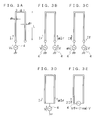
- the folded antenna for example, shown in Fig. 3A, having a length of L, widths of ⁇ 1 and ⁇ 2 and an interval of d, is understood by dividing into an even mode of currents Ir of both segments flowing in a same direction, as shown in Fig. 3B, and an odd mode of currents If flowing in a reverse direction, as shown in Fig. 3C.
- the even mode and the odd mode shown in Figs. 3B and 3C can be replaced by equivalent circuits shown in Fig. 3D and 3E, respectively by simplifying with communizing the feeding part 4.
- Figs. 3A having a length of L, widths of ⁇ 1 and ⁇ 2 and an interval of d
- Ii represents a current fed to the folded antenna, Vi a voltage fed to the folded antenna, Ir a current fed to segments of the even mode in case of dividing into the even mode and the odd mode, If a current fed in odd mode and V a feeding voltage respectively.
- An ⁇ is a factor relating to a coupling of turning parts represented by equation (2) described later.
- an input impedance Zr of the antenna in the even mode is represented by next equation (1).
- Zr V / 1 + ⁇ Ir
- ⁇ is represented as next equation (2).
- ⁇ cosh - 1 ⁇ 2 - ⁇ 2 + 1 2 ⁇ cosh - 1 ⁇ 2 - ⁇ 2 - 1 2 ⁇ ⁇ ⁇
- ⁇ d/ ⁇ 1
- ⁇ ⁇ 2/ ⁇ 1
- L is an electrical length of the entire antenna element 1 turned back.
- the input impedance of equation (3) and equation (1) has an approximately constant value even if the resonance frequency varies, although ⁇ , that is the width ⁇ of the antenna or the distance d between the turning parts varies, and the impedance of equation (4) has a wide band to the resonance frequency.
- f1 can be from 2.4 to 2.5 GHz and f3 to f4 can be from 5 to 6 GHz.
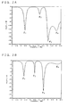
- a return loss to the frequency of the antenna is shown in Fig. 2A and the return loss to the frequency of the antenna in case that the length of each segment is not varied, or in case of turning back by a constant length, is shown comparatively in Fig 2B.
- the desired resonance frequencies of 2.4 to 2.5 GHz and 5 to 6 GHz can be obtained by the folded antenna in which the lengths of the segments increase gradually, but the resonance frequency of 5 to 6 GHz can not be obtained by the antenna in which the segments have same length.
- a relationship between the lengths of two adjacent segments which gradually increase is not limited to the above-described example, and the relationship between the lengths of two adjacent segments can be adjusted from 1.05 to 2 times, for example 1.5 times, such that a desired bandwidth at a desired frequency and a desired impedance are obtained.
- adjusting of the frequencies becomes easy by forming the intervals between the segments to be not same but different, and adjusting the resonance frequency becomes also easy by varying the widths of the segments further.
- adjustments to get the relationship of the frequency described above and the desired impedance are performed not only by turning back the antenna element simply but also by increasing gradually the lengths of the segments between the turning parts as the segments are away from the ground plate and by varying the widths of the segments and the intervals between two adjacent segments by two or more different values.
- mass production is capable by producing by using the same dimensions.
- the ground conductor film 2 is extended on the surface of the dielectric base 3 but it can be allowed to be formed only on the side surface (a bottom surface).
- the antenna element is formed not only by turning back simply but also by turning back so that the segments formed by turning back are parallel to the one face of the ground plate (the ground conductor 2) provided on the side of the feeding part 4 (perpendicular to the direction in which the antenna element extending mainly) and that the lengths of L 1 to L 3 of each segment increase in order.
- a capacitance between the ground plate and the segment can be reduced, the input impedance can be prevented from reducing and the desired impedance can be obtained by adjusting the intervals between the segments or the like.
- the resonance frequency f1 to f4 can be adjusted by adjusting the lengths of the segments and the intervals between segments. As shown in Fig.
- an antenna has been developed which resonates at f1 of a frequency of 2.4 to 2.5 GHz (a fractional bandwidth of approximately 4%), and resonates at a frequency of 5 GHz with a bandwidth of approximately 1 GHz (a fractional bandwidth of approximately 18%) by setting f3 and f4 very closely.
- the antenna 20 described above is mounted on a substrate 21 loaded in wireless LANs or portable telephones as shown in Fig. 1B.
- a ground conductor 22 is formed and connected to the ground conductor film 2 of the antenna 20.
- the feeding wiring 23 is connected to the feeding part 4 of the antenna 20 and its another end part is leaded to the surface of the substrate 21 and connected to the transmitting and receiving circuit formed on the surface.
- a distance D an impedance of the antenna 20 can be further adjusted.
- the one face of the ground plate corresponds still to the ground conductor film 2 formed on the side surface of the dielectric base 3.
- the one face in the relationship between the direction of extending antenna element and the one face of the ground plate means a face in a direction of thickness of the ground conductor film 22 (perpendicular to the paper) at an end face 22a of the ground conductor film 22 nearest the feeding part 4.
- the antenna in case that the antenna is mounted in a substrate of wireless LANs, the antenna can be mounted so as to turn a face, on which the antenna 1 is formed, to a side of the substrate 21 as shown in Fig. 4, in place that the antenna 20 is mounted such that the face on which the antenna is formed is outside as shown in Fig. 1B.
- same numerals are employed for same parts as those in Fig. 1 and explanations are omitted.
- the antenna 20 can be formed inside the dielectric base 3 as shown in Figs. 5A and 5B which are a perspective view and an explanatory B-B' cross section, in place that the antenna 1 is exposed at a top face in Fig. 1B.
- the antenna of this type can be formed by steps of, for example, forming a plurality of the antenna elements 1 described above on a surface of a first ceramic sheet 31 of wide sheet, laminating a second ceramic sheet 32 on it, dividing into each antenna and sintering, forming the feeding part 4 and the ground conductor 2 made of a conductor film on an end part of the antenna 1 by painting conductor paste, and sintering.
- the antenna element 1 extends in a direction perpendicular to the one face of the ground conductor 2, and satisfies the relationship described above.
- member 35 and 36 are formed as lands which are formed on a back face of the ceramic sheet 31 for soldering to the substrate 21 or the like.
- productivity is raised remarkably because many of antenna elements can be formed by printing in a wide ceramic sheet which can be scribed and sintered.
- the pattern is formed so that the segments of different lengths are formed for the other side opposite as to a parallel line (an end face of the ceramic base 3) at a constant distance from the center line of the segment 11 extending perpendicular to the ground conductor film 2 on the side of the feeding part 4 (an end part of an antenna element 1).
- the antenna which have desired bandwidths at desired frequency bands of the first and the second can be obtained by adjusting the lengths, the widths and the intervals of the segments. Patterns of this kind are shown below.
- FIG. 6 An example shown in Fig. 6 is an antenna in which the segments are turned back symmetrically as to a center line of an axis of the segment 1a (the axis perpendicular to the ground plate 2) connected to the feeding part 4 and increase gradually.
- the antenna element can be formed on a ceramic substrate, inside a dielectric base by laminating dielectric sheets or by a simple metal wire. In such case of symmetry, adjusting resonance frequency can be performed easily.
- FIG. 7 An example shown in Fig. 7 is same type as the example shown in Fig. 6, but in this example, turning part is not perpendicular to the segments parallel to the ground plate 2, but oblique, and the other structure is same as that shown in Fig. 6. By turning back oblique, an antenna of a wider bandwidth can be easily obtained.
- the antenna element is turned back to only one side (left side in Fig. 8) as to an axis of the segment 1a connected to the feeding part 4, and the lengths of the segments between the turning parts increase gradually.
- the base line of the turning parts in Fig. 1A is a center line of the segment 1a connected to the feeding part 4, and the other structure is same as that shown in Fig. 1. It is a merit of this type to obtain an antenna of wide bandwidth easily.
- FIG. 9 An example shown in Fig. 9 is the antenna element in which turning parts in the structure shown in Fig. 8 are formed oblique, same as the example shown in Fig. 7. Turning back like this has merits of examples shown in Figs. 7 and 8.
- the above-described example is an antenna of two frequency bands of 2.4 GHz and 5 GHz, but frequency bands are not limited to these, and this structure is effective to get resonance at two or more frequency bands, having a resonance characteristics of a wide bandwidth specially at a high frequency, only by a single antenna.
- the antenna according to the present invention can be employed for wireless LANs, portable telephones, Zig Bee (a standard for short-distance wireless communications for home electrical appliances, technology of same kind as Bluetooth) or the like.
Landscapes
- Engineering & Computer Science (AREA)
- Microelectronics & Electronic Packaging (AREA)
- Details Of Aerials (AREA)
- Waveguide Aerials (AREA)
Applications Claiming Priority (2)
| Application Number | Priority Date | Filing Date | Title |
|---|---|---|---|
| JP2004083314A JP3863533B2 (ja) | 2004-03-22 | 2004-03-22 | 折返しアンテナ |
| PCT/JP2005/004793 WO2005091436A1 (ja) | 2004-03-22 | 2005-03-17 | 折返しアンテナ |
Publications (2)
| Publication Number | Publication Date |
|---|---|
| EP1729367A1 true EP1729367A1 (de) | 2006-12-06 |
| EP1729367A4 EP1729367A4 (de) | 2009-11-04 |
Family
ID=34994014
Family Applications (1)
| Application Number | Title | Priority Date | Filing Date |
|---|---|---|---|
| EP05726669A Withdrawn EP1729367A4 (de) | 2004-03-22 | 2005-03-17 | Gefaltete antenne |
Country Status (5)
| Country | Link |
|---|---|
| US (1) | US7598921B2 (de) |
| EP (1) | EP1729367A4 (de) |
| JP (1) | JP3863533B2 (de) |
| CN (1) | CN1934752A (de) |
| WO (1) | WO2005091436A1 (de) |
Cited By (3)
| Publication number | Priority date | Publication date | Assignee | Title |
|---|---|---|---|---|
| EP2040332A1 (de) * | 2007-09-20 | 2009-03-25 | Delta Networks, Inc. | Multimodale resonante Breitbandantenne |
| EP2040331A1 (de) * | 2007-09-20 | 2009-03-25 | Delta Networks, Inc. | Bestückte und intelligente Monopolantenne für einen WLAN-AP/Router |
| EP2719018B1 (de) * | 2011-06-08 | 2020-01-01 | Amazon Technologies, Inc. | Mehrbandantenne |
Families Citing this family (25)
| Publication number | Priority date | Publication date | Assignee | Title |
|---|---|---|---|---|
| JP4999349B2 (ja) | 2006-04-05 | 2012-08-15 | 株式会社ソニー・コンピュータエンタテインメント | アンテナおよびそれを利用した無線通信装置 |
| JP2008154013A (ja) * | 2006-12-19 | 2008-07-03 | Nissei Electric Co Ltd | アンテナエレメント |
| JP4880439B2 (ja) * | 2006-12-21 | 2012-02-22 | 日星電気株式会社 | アンテナエレメント |
| JP4950689B2 (ja) * | 2007-02-09 | 2012-06-13 | 株式会社フジクラ | アンテナおよびこのアンテナを搭載した無線通信装置 |
| EP1973192B1 (de) * | 2007-03-23 | 2017-06-14 | BlackBerry Limited | Antennenvorrichtung und entsprechendes Verfahren für ein Multiband-Radiogerät |
| JP4974168B2 (ja) * | 2007-10-02 | 2012-07-11 | 古河電気工業株式会社 | レーダ装置用アンテナ |
| JP5052679B2 (ja) | 2008-01-15 | 2012-10-17 | カーディアック ペースメイカーズ, インコーポレイテッド | アンテナを有する埋込型医療デバイス |
| US8704729B2 (en) * | 2008-06-26 | 2014-04-22 | Kevin B Tucek | Extended varying angle antenna for electromagnetic radiation dissipation device |
| US8188926B2 (en) * | 2008-10-31 | 2012-05-29 | Silicon Laboratories, Inc. | Folded antenna structures for portable devices |
| CN101740878B (zh) * | 2008-11-14 | 2013-05-29 | 深圳富泰宏精密工业有限公司 | 多频天线 |
| US8159401B2 (en) * | 2009-01-16 | 2012-04-17 | Badger Meter, Inc. | Antenna for sealed transmitter assembly in subsurface utility installations |
| JP2011015120A (ja) * | 2009-07-01 | 2011-01-20 | Panasonic Corp | 受信装置 |
| EP2486624B1 (de) * | 2009-10-05 | 2015-03-25 | Cardiac Pacemakers, Inc. | Mehrbandantenne für eine implantierbare vorrichtung |
| GB2493373A (en) * | 2011-08-03 | 2013-02-06 | Harada Ind Co Ltd | Antenna with a bent conductor for multiple frequency operation |
| JP5626483B2 (ja) * | 2012-06-08 | 2014-11-19 | 株式会社村田製作所 | アンテナおよび無線通信装置 |
| US10206649B2 (en) * | 2015-12-29 | 2019-02-19 | Analogic Corporation | Data transfer across a rotating boundary of a computed tomography imaging apparatus |
| JP6461061B2 (ja) * | 2016-09-22 | 2019-01-30 | 株式会社ヨコオ | アンテナ装置 |
| US10256529B2 (en) | 2016-11-15 | 2019-04-09 | Starkey Laboratories, Inc. | Hearing device incorporating conformal folded antenna |
| KR101965226B1 (ko) * | 2017-10-23 | 2019-08-27 | 중앙대학교 산학협력단 | 안테나 장치 |
| JP6978969B2 (ja) * | 2018-03-23 | 2021-12-08 | Fdk株式会社 | アンテナ装置 |
| CN114503365B (zh) * | 2019-10-03 | 2025-07-15 | 株式会社村田制作所 | 天线装置以及具备天线装置的无线通信设备 |
| JP7104089B2 (ja) * | 2020-03-13 | 2022-07-20 | 矢崎総業株式会社 | 折り返しアンテナ |
| CN111446546B (zh) * | 2020-05-12 | 2024-02-27 | 珠海格力电器股份有限公司 | 多频天线装置 |
| TWI765743B (zh) * | 2021-06-11 | 2022-05-21 | 啓碁科技股份有限公司 | 天線結構 |
| JP2024080801A (ja) * | 2022-12-05 | 2024-06-17 | Tdk株式会社 | アンテナ装置 |
Family Cites Families (17)
| Publication number | Priority date | Publication date | Assignee | Title |
|---|---|---|---|---|
| US3355740A (en) * | 1966-04-04 | 1967-11-28 | Univ Illinois | Log-periodic zig zag antenna |
| US4286271A (en) * | 1979-02-26 | 1981-08-25 | Gte Products Corporation | Log-periodic monopole antenna |
| JPH06508732A (ja) * | 1991-06-27 | 1994-09-29 | シーメンス アクチエンゲゼルシヤフト | 平面状蛇行アンテナ |
| US5872546A (en) * | 1995-09-27 | 1999-02-16 | Ntt Mobile Communications Network Inc. | Broadband antenna using a semicircular radiator |
| JP2898921B2 (ja) | 1996-06-20 | 1999-06-02 | 株式会社ヨコオ | アンテナおよび無線機 |
| JPH11168318A (ja) * | 1997-10-03 | 1999-06-22 | Nippon Telegr & Teleph Corp <Ntt> | 多周波共用セクタアンテナ装置 |
| GB2330951B (en) * | 1997-11-04 | 2002-09-18 | Nokia Mobile Phones Ltd | Antenna |
| US5986609A (en) * | 1998-06-03 | 1999-11-16 | Ericsson Inc. | Multiple frequency band antenna |
| TW513829B (en) * | 2000-10-12 | 2002-12-11 | Furukawa Electric Co Ltd | Small antenna |
| JP2002232223A (ja) * | 2001-02-01 | 2002-08-16 | Nec Corp | チップアンテナおよびアンテナ装置 |
| JP2002314322A (ja) * | 2001-02-07 | 2002-10-25 | Furukawa Electric Co Ltd:The | 小型アンテナ |
| US6674405B2 (en) * | 2001-02-15 | 2004-01-06 | Benq Corporation | Dual-band meandering-line antenna |
| JP2002368517A (ja) * | 2001-06-08 | 2002-12-20 | Hitachi Metals Ltd | 表面実装型アンテナおよびそれを搭載した通信機器 |
| JP3952385B2 (ja) * | 2001-06-15 | 2007-08-01 | 日立金属株式会社 | 表面実装型アンテナ及びそれを搭載した通信機器 |
| KR100444219B1 (ko) * | 2001-09-25 | 2004-08-16 | 삼성전기주식회사 | 원형편파용 패치 안테나 |
| JP2003218623A (ja) | 2002-01-18 | 2003-07-31 | Ngk Insulators Ltd | アンテナ装置 |
| JP2003273628A (ja) * | 2002-03-19 | 2003-09-26 | Taiyo Yuden Co Ltd | 誘電体アンテナ |
-
2004
- 2004-03-22 JP JP2004083314A patent/JP3863533B2/ja not_active Expired - Fee Related
-
2005
- 2005-03-17 CN CN200580009140.4A patent/CN1934752A/zh active Pending
- 2005-03-17 WO PCT/JP2005/004793 patent/WO2005091436A1/ja not_active Ceased
- 2005-03-17 US US10/593,714 patent/US7598921B2/en not_active Expired - Fee Related
- 2005-03-17 EP EP05726669A patent/EP1729367A4/de not_active Withdrawn
Cited By (4)
| Publication number | Priority date | Publication date | Assignee | Title |
|---|---|---|---|---|
| EP2040332A1 (de) * | 2007-09-20 | 2009-03-25 | Delta Networks, Inc. | Multimodale resonante Breitbandantenne |
| EP2040331A1 (de) * | 2007-09-20 | 2009-03-25 | Delta Networks, Inc. | Bestückte und intelligente Monopolantenne für einen WLAN-AP/Router |
| US7619582B2 (en) | 2007-09-20 | 2009-11-17 | Delta Networks, Inc. | Printed monopole smart antenna for WLAN AP/router |
| EP2719018B1 (de) * | 2011-06-08 | 2020-01-01 | Amazon Technologies, Inc. | Mehrbandantenne |
Also Published As
| Publication number | Publication date |
|---|---|
| US7598921B2 (en) | 2009-10-06 |
| US20080238778A1 (en) | 2008-10-02 |
| CN1934752A (zh) | 2007-03-21 |
| JP3863533B2 (ja) | 2006-12-27 |
| EP1729367A4 (de) | 2009-11-04 |
| WO2005091436A1 (ja) | 2005-09-29 |
| JP2005277448A (ja) | 2005-10-06 |
Similar Documents
| Publication | Publication Date | Title |
|---|---|---|
| US7598921B2 (en) | Folded antenna | |
| EP1538703B1 (de) | Antenne und elektronisches gerät | |
| JP3340374B2 (ja) | 多周波アンテナ | |
| KR100283459B1 (ko) | 2주파 공진안테나장치 | |
| US7755545B2 (en) | Antenna and method of manufacturing the same, and portable wireless terminal using the same | |
| US7053837B2 (en) | Multi-layered multi-band antenna | |
| CN103765677B (zh) | 平面倒f天线 | |
| JPH09260934A (ja) | マイクロストリップアンテナ | |
| EP0871238A2 (de) | Breitbandige Antenne mit kurzgeschlossenen Mikrostreifenleitern | |
| US20050057401A1 (en) | Small-size, low-height antenna device capable of easily ensuring predetermined bandwidth | |
| CN103765678B (zh) | 平面倒f天线 | |
| US6864854B2 (en) | Multi-band antenna | |
| JPH09219619A (ja) | 表面実装型アンテナおよびこれを用いた通信機 | |
| WO2019107382A1 (ja) | アンテナ装置 | |
| US6262682B1 (en) | Micro-strip antenna | |
| JP4148126B2 (ja) | アンテナ装置及びこれを備えた通信機器 | |
| JP2013530623A (ja) | 平面導電素子を有するアンテナ | |
| US7924233B2 (en) | Three-dimensional antenna and related wireless communication device | |
| JPH09232854A (ja) | 移動無線機用小型平面アンテナ装置 | |
| CN117954837A (zh) | 天线、天线玻璃和交通工具 | |
| JPH09232856A (ja) | 平面アンテナ | |
| US7728773B2 (en) | Multi-band antenna | |
| US7482980B2 (en) | Three-dimensional wideband antenna and related wireless communication device | |
| US20100225545A1 (en) | Capacitive-feed antenna and wireless communication apparatus having the same | |
| KR100586038B1 (ko) | 마이크로 스트립 패치 안테나 |
Legal Events
| Date | Code | Title | Description |
|---|---|---|---|
| PUAI | Public reference made under article 153(3) epc to a published international application that has entered the european phase |
Free format text: ORIGINAL CODE: 0009012 |
|
| 17P | Request for examination filed |
Effective date: 20060919 |
|
| AK | Designated contracting states |
Kind code of ref document: A1 Designated state(s): DE FI SE |
|
| DAX | Request for extension of the european patent (deleted) | ||
| RBV | Designated contracting states (corrected) |
Designated state(s): DE FI SE |
|
| A4 | Supplementary search report drawn up and despatched |
Effective date: 20091006 |
|
| RIC1 | Information provided on ipc code assigned before grant |
Ipc: H01Q 1/22 20060101ALI20090930BHEP Ipc: H01Q 9/38 20060101ALI20090930BHEP Ipc: H01Q 5/01 20060101ALI20090930BHEP Ipc: H01Q 9/42 20060101AFI20051004BHEP Ipc: H01Q 1/38 20060101ALI20090930BHEP Ipc: H01Q 13/20 20060101ALI20090930BHEP |
|
| STAA | Information on the status of an ep patent application or granted ep patent |
Free format text: STATUS: THE APPLICATION IS DEEMED TO BE WITHDRAWN |
|
| 18D | Application deemed to be withdrawn |
Effective date: 20100105 |