EP1729401A2 - Dispositif électrique d'entraînement linéaire avec capteur fin de course - Google Patents
Dispositif électrique d'entraînement linéaire avec capteur fin de course Download PDFInfo
- Publication number
- EP1729401A2 EP1729401A2 EP06010898A EP06010898A EP1729401A2 EP 1729401 A2 EP1729401 A2 EP 1729401A2 EP 06010898 A EP06010898 A EP 06010898A EP 06010898 A EP06010898 A EP 06010898A EP 1729401 A2 EP1729401 A2 EP 1729401A2
- Authority
- EP
- European Patent Office
- Prior art keywords
- housing
- spindle
- electrolinear
- plunger
- drive according
- Prior art date
- Legal status (The legal status is an assumption and is not a legal conclusion. Google has not performed a legal analysis and makes no representation as to the accuracy of the status listed.)
- Withdrawn
Links
Images


Classifications
-
- H—ELECTRICITY
- H02—GENERATION; CONVERSION OR DISTRIBUTION OF ELECTRIC POWER
- H02K—DYNAMO-ELECTRIC MACHINES
- H02K7/00—Arrangements for handling mechanical energy structurally associated with dynamo-electric machines, e.g. structural association with mechanical driving motors or auxiliary dynamo-electric machines
- H02K7/06—Means for converting reciprocating motion into rotary motion or vice versa
-
- F—MECHANICAL ENGINEERING; LIGHTING; HEATING; WEAPONS; BLASTING
- F16—ENGINEERING ELEMENTS AND UNITS; GENERAL MEASURES FOR PRODUCING AND MAINTAINING EFFECTIVE FUNCTIONING OF MACHINES OR INSTALLATIONS; THERMAL INSULATION IN GENERAL
- F16H—GEARING
- F16H25/00—Gearings comprising primarily only cams, cam-followers and screw-and-nut mechanisms
- F16H25/18—Gearings comprising primarily only cams, cam-followers and screw-and-nut mechanisms for conveying or interconverting oscillating or reciprocating motions
- F16H25/20—Screw mechanisms
- F16H25/2015—Means specially adapted for stopping actuators in the end position; Position sensing means
-
- H—ELECTRICITY
- H02—GENERATION; CONVERSION OR DISTRIBUTION OF ELECTRIC POWER
- H02K—DYNAMO-ELECTRIC MACHINES
- H02K11/00—Structural association of dynamo-electric machines with electric components or with devices for shielding, monitoring or protection
- H02K11/20—Structural association of dynamo-electric machines with electric components or with devices for shielding, monitoring or protection for measuring, monitoring, testing, protecting or switching
- H02K11/21—Devices for sensing speed or position, or actuated thereby
-
- H—ELECTRICITY
- H02—GENERATION; CONVERSION OR DISTRIBUTION OF ELECTRIC POWER
- H02K—DYNAMO-ELECTRIC MACHINES
- H02K2211/00—Specific aspects not provided for in the other groups of this subclass relating to measuring or protective devices or electric components
- H02K2211/03—Machines characterised by circuit boards, e.g. pcb
-
- H—ELECTRICITY
- H02—GENERATION; CONVERSION OR DISTRIBUTION OF ELECTRIC POWER
- H02K—DYNAMO-ELECTRIC MACHINES
- H02K5/00—Casings; Enclosures; Supports
- H02K5/04—Casings or enclosures characterised by the shape, form or construction thereof
- H02K5/10—Casings or enclosures characterised by the shape, form or construction thereof with arrangements for protection from ingress, e.g. water or fingers
Definitions
- the invention relates to an electric linear drive with limit switch according to the preamble of claim 1.
- Such electrolinear drives can be used as adjusting devices for adjusting moving parts with considerable forces manifold, such as for smoke and heat exhaust ventilation flaps, especially as components of smoke and heat ventilation systems, ventilation wings, ventilation blinds, skylights and belts with ventilation function, Butterfly valves for pipe and duct ventilation devices, windows and doors.
- Prior art electroluminescent actuators include a torque tube which is displaced by an electric motor via gear means including a spindle which is rotated by the electric motor and engages a spindle nut fixedly connected to the torque tube. Since the electric linear drive can be exposed to the weather or otherwise moisture influences, moisture-sensitive electrical components are arranged sealed in a housing of the linear drive to the outside. The seal of the housing interior is, however, in particular, as a result of the led out of the housing and the thrust pipe produced by him and the spindle nut when actuated in the housing suction at best to achieve with elaborate structural means or seals.
- a known from practice electrolinear drive with limit in two end positions of a push tube of the type mentioned comprises a divided by a central bearing plate into two housing sections housing.
- an electric motor and a load shedding board are arranged with electrical components for the end stop of the electric motor.
- the limit stop is to shut off the electric motor when the torque tube has reached one of its possible end positions and to avoid mechanical overloading of the electric linear drive and / or elements actuated by it as well as thermal overload of the electric motor when the torque tube is "on block". drove.
- limit switch boards are electrically connected to the load control board of the motor controller in the first housing section via leads passing through an opening in the bearing plate.
- the central bearing plate does not seal the two housing sections against moisture. It serves to accommodate in a ball bearing and a spindle sleeve in which an end-side pin of the spindle is rotatably mounted, the is in communication with a transmission output of the engine.
- the spindle is connected in a force-transmitting manner in the second housing section via the displaceably guided spindle nut to the torque tube, which protrudes out of the second housing section through an end-side housing cover.
- the housing cover receives a scraper, through which the torque tube is passed. - With the scraper in the frontal housing cover and by further sealing measures the entire housing interior, which comprises the first housing portion and the second housing portion to be sealed to the outside against moisture, but this is not always achieved permanently for the reasons mentioned above.
- the present invention is therefore an object of the invention to improve the sealing of the housing interior, which receives electrical parts to the outside against moisture with uncomplicated design means.
- the essence of the invention is that not the entire housing of the electric linear drive is sealed to the outside, but only the first housing portion which receives the electric motor, said first portion is sealed against the second housing portion against moisture, namely in the region of a storage of Spindle, with which the torque tube is actuated, as well as on a plunger unit which transmits in End eins Silveren the torque tube a limited shift in the first housing section, in which the limit switches are arranged, with which the electric motor is automatically switched off in one of the end positions of the torque tube.
- the second housing section which essentially requires the spindle and the optionally actuated by a spindle nut torque tube includes, as far as the latter is not extended, not to be protected from the outside tight against the ingress of moisture.
- the inventive design of the electric linear drive is additionally achieved that due to the displacement of the limit switch from the second housing section in which they would normally be operated, in the first housing section, the assembly of the entirety of the electrical components of the electric linear drive can be simplified by the limit switches, for example are arranged on a circuit board of a printed circuit in the first housing section, which accommodates further components for the load shutdown of the electric motor, see claim 11.
- the plunger unit with spring-loaded centering in combination which are suitable to center outside of the end positions of the thrust tube not mitschobene with this plunger unit in a starting position.
- This centering is thus in view of the fact that the second portion of the plunger unit in the second housing portion, in which optionally the torque tube and the spindle nut are located, is suitable to be mitschoben only in End too Kunststoffen the torque tube with this.
- the plunger unit is thus not permanently fixedly coupled to the torque tube or the spindle nut, which can facilitate the production of the linear drive, because it allows the plunger unit to limit shift by a defined distance can be moved, which is independent of the mutual distance of the end positions of the torque tube.
- a compact design of the spring-loaded centering means has the features of claim 3, that it comprises a compression spring between two sliding discs and two lock washers which are mounted at a distance from each other on the ram unit that they include the loaded by the compression spring sliding discs that the sliding discs be in the initial position of the plunger unit under the load of the compression spring to housing fixed stops, and that each of the two sliding was suitable to be moved with one of the two lock washers together with the plunger unit against the load by the compression spring of the adjacent stop away.
- the centering ensure the centering of the plunger unit in its initial position and on the other hand allow a displacement of the plunger unit for actuating the limit switch when the torque tube or the spindle nut is in one of its end position ranges and accordingly entrains the plunger unit.
- a first of the two stops formed by a recess in the bearing plate which at least partially receives one of the two sliding discs and beyond can be designed so that it slidingly guides this sliding disk, while a second of the two Stops at a fixed distance from the first stop in the second housing portion is arranged.
- the spring-loaded centering arranged in recesses of the bearing plate and a voltage applied to her back plate, the ram unit through the bearing plate and the counter-plate concentrically extends to the spring-loaded centering, by a in the Counter-plate arranged seal which seals the recesses of the bearing plate and the counter-plate relative to the second housing portion.
- a spindle nut in a conventional manner to a housing inner end of the torque tube is slidably mounted and guided together with the push tube, the second portion of the ram unit is suitably designed so that it is moved along with the spindle nut when the torque tube is pushed by the spindle nut in one of its two end position ranges.
- the spindle nut having a sliding nut with a lug which is adapted to move the second portion of the plunger unit in end positions of the torque tube with.
- the ram unit can have drivers or stops, one of which in each case comes into contact with the shoulder of the sliding nut in one of the end positions of the torque tube.
- the bearing plate between the first housing portion and the second housing portion receive a spindle bearing, a seal of the spindle bearing and a seal of the plunger unit.
- this plunger unit has a displaceable in the second housing portion sheet metal part with two spaced-apart angled stops, which are adapted to be taken from the spindle nut in End eins Colouren the spindle nut or the torque tube, and a with the Sheet metal part in solid compound plunger, which extends sealed against the second housing portion in the first housing portion.
- This ram unit can be manufactured with simple conventional tools, namely by punching the sheet metal part, bending the angled stops and turning the plunger. This embodiment is particularly suitable for smaller quantities of the electric linear drive with end stop.
- the displaceable sheet metal part can be performed according to claim 1 3 easily in a housing-fixed groove in the second housing section.
- a second embodiment of the ram unit according to claim 14 requires the production of a special profile bar.
- This is slidably mounted to the second housing section. In their ends screws are screwed with laterally protruding screw heads to the spindle nut in End eins Colouren the spindle nut or the To be taken along push tube.
- the profile bar is connected to a plunger in a fixed connection, which extends through the bearing plate and possibly the voltage applied to her back plate and is suitable with its first portion in the first housing portion to actuate the limit switch.
- profile bars requires special manufacturing facilities to form a continuous profile. From this then profile bars of the desired length can be easily cut off, after which they can be provided with frontal screws for driving through the spindle nut. By cutting the profile bar to length from a longer profile, electropower drives with limit stops at different end positions of the torque tube can be produced efficiently.
- the profile bar is formed with the features that it has a lower cross-sectionally approximately cylindrical part with a threaded bore, from the top of an extension is formed with a continuous threaded hole, which receives the two screws at the end, that the extension of two inside
- the guide means formed in the second housing section are encompassed, and in that a groove is formed at the bottom from the approximately cylindrical part and rests on a web formed from the second housing section.
- the groove and the web formed from the second housing portion serve in conjunction with the molded from the second housing portion guide lugs for exact guidance of the profile bar in the second housing portion.
- the plunger and the profile bar made of aluminum, which can be processed well and allows a relatively low-mass design of the electric linear drive.
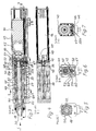
- FIGS. 1 and 2 two housing sections of a first embodiment of an electrolinear drive are designated 1 and 2.
- the two housing sections 1 and 2 are separated according to the detailed illustrated first embodiment in Figure 2 by a bearing plate 3.
- an electric motor 4 with a gear 5 and a load shedding board 6 are arranged in the first housing section 1.
- the limit switches 8, 9 are located in the first housing section 1.
- the first housing section 1 is sealed to the outside with respect to moisture, in particular with a cable seal 1 2, through which a connecting cable 13 is inserted into the first housing section.
- first housing portion 1 is also relative to the second housing portion 2, which includes a spindle 14 and a thrust tube 15 substantially, at the inner end of a spindle nut 1 6 sits, in which engages the spindle.
- An outer end of the spindle is mounted in the torque tube by means of a centering ring 17, see Figure 2.
- An outer end of the torque tube is guided by a frontal housing cover 18 to the outside and penetrates this purpose a scraper 19 in the lid.
- a pipe plug 20 closes the torque tube 1 5 at its outer end and serves to connect the torque tube with a part to be adjusted by this.
- An inner end of the spindle 14 is formed as a pin and is received by a spindle bolt 21 which is mounted by means of a ball bearing 22 in a spindle sleeve 23 which is sealed with a seal 24 in the bearing plate 3.
- the inner end of the spindle is connected to an unspecified output of the transmission 5 for transmitting a torque.
- an elongated ram unit generally designated 25 is. It consists essentially of a plunger 26 with a fixed thereto in the second housing section 2 slidable strip-shaped sheet metal part 27.
- the elongated plunger unit 25 thus extends substantially parallel to the torque tube 1 5 in the second housing section 2 and through the bearing plate 3 therethrough in the first housing portion 1, in which a contour is formed on the plunger end for actuating the actuating elements 10, 11 of the limit switches 8, 9.
- the plate member 27 connected to the plunger 26 has in the second housing portion angled stops 28, 29 which are suitable in End eins Colouren the torque tube 15 and the associated spindle nut 16, to be actuated by the spindle nut 16, see Figure 2.
- angled stops 28, 29 which are suitable in End eins Buffaloen the torque tube 15 and the associated spindle nut 16, to be actuated by the spindle nut 16, see Figure 2.
- the spindle nut 16 interacts directly with drivers 28a, 29a, which correspond to the angled stops 28, 29 in Figure 2.
- the ram unit 25 is centered in a central position when the angled stops 28, 29 and drivers 28a, 29a are not loaded or shifted, with spring-loaded centering, which are generally designated 32, see Figure 2, in a middle Centered starting position, which is shown in Figure 1.
- the ram unit 25 is near its inner or right end position.
- the spring-loaded centering means 32 comprise a compression spring 33 which presses apart two sliding disks 34, 35 displaceable on the plunger 26, specifically until it rests against each other at a mutual distance arranged locking washers 36, 37, which sit firmly in not designated grooves of the plunger 26.
- angled stops 28, 29 it is noted that these must not be prepared as separate parts and fixed to the sheet metal part 27, but also can be formed integrally formed directly from the sheet metal part.
- the motor 4 which pushes the torque tube 15 by means of the spindle 14 to the outside, is thereby switched off via the electronics of the load shedding board 6, which can also be referred to as Endabschaltplatine.
- the motor can then be turned on externally in the opposite direction of rotation, whereby the torque tube is retracted and the plunger 26 is returned under the action of the compression spring 33 back into its mean starting position.
- the second embodiment of the electric linear drive according to Figures 3 to 7 differs from the first embodiment, in particular according to Figure 2, once in that between a first housing portion 40 and a second housing portion 41 except a bearing plate 42 on the bearing plate on the side of the second Housing portion 41 lying counter-plate 43 are arranged.
- the electric motor 44 with a gear 45 and a circuit board 46 are arranged, which carries a load shedding electronics and limit switches 47, 48.
- the second housing portion 41 in turn includes the majority of a spindle 49, the unnamed pin is connected to an output of the transmission 45 in torque transmitted connection and is mounted via a spindle bolt 50 in a ball bearing 51 and a spindle sleeve 52 which is arranged in the counter-plate ,
- the spindle 49 engages a spindle nut 53 which is attached to an inner end of a push tube 54.
- a sliding nut 53 a On the spindle nut 53 sits a sliding nut 53 a, which is suitable to cooperate with a generally designated 55 ram unit.
- the ram unit 55 differs from the first embodiment:
- the ram unit 55 although in turn comprises a plunger 55 a, of which one end, which is located in the first housing portion 40 is designed so that there are unnamed actuators of the limit switch 47 , 48 can press.
- This plunger extends through the bearing plate 42 and through the counter-plate 43 into the second housing portion 41, through a seal 56, which is arranged here in the counter-plate 43.
- one end of the plunger 55a is screwed into a sliding in the second housing portion 41 profile rod 57, in a threaded bore 58, see Figure 4.
- the cross-section of the profile bar 57 which expediently consists of aluminum, results from FIG. 6: It can be seen that the profile bar 57 has a lower cross-sectionally approximately cylindrical part 59, through which the threaded bore 58 for the ram passes centrally. At its lowest point, the cylindrical part 59 has a groove 60 which rests on a web 61 formed from the second housing portion 41 inside. Upwardly extends from the cylindrical portion 59, a narrower extension 62 which is encompassed by guide lugs 72, 73, which are formed from the second housing portion 41. In the extension 62, a continuous threaded hole 63 is provided, which receives at each end of the profile rod 57 a screwed screw 64 and 65 with laterally projecting screw head.
- the screw heads are arranged so that they are taken from the spindle nut 53 and sitting on the spindle nut slide nut 53a in End eins Buffaloen the torque tube 54 and the spindle nut 53, including the sliding nut not designated depressions on both sides of a lug 66.
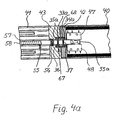
- centering 67 are in frictional connection, which are constructed substantially like the centering means 32 of Figure 2, which is why matching components are provided with the same reference numerals.
- the centering means 67 are illustrated in FIG. 4a. It can be seen that a stop of a left sliding washer 35 a is formed by a recess in the counter-plate 43.
- the centering means 67 are arranged in a chamber 68, which is formed on the one hand from the bearing plate 42 and on the other hand from the counter plate 44.
- the chamber 68 is sealed relative to the second housing portion 41 by the seal 56 in the backing plate 43.
- the counter-plate 43 also receives a seal 69 of the spindle sleeve 52.
- the first housing portion 40 is protected against the ingress of moisture, even if the scraper 19 and a further seal 70 on a housing cover 71 through which an outer end portion of the torque tube 54 is guided with the pipe plug 20, see Figure 3, should only cause an incomplete seal.
- the centering 67 including the compression spring 33a centered in their middle position ram unit 55 is a reliable two-sided limit in end positions of the torque tube, which can be determined flexibly and accurately by the length and arrangement of the profile bar and screwed into them without changing the mounting position of the limit switch.
Landscapes
- Engineering & Computer Science (AREA)
- Power Engineering (AREA)
- General Engineering & Computer Science (AREA)
- Microelectronics & Electronic Packaging (AREA)
- Mechanical Engineering (AREA)
- Transmission Devices (AREA)
- Connection Of Motors, Electrical Generators, Mechanical Devices, And The Like (AREA)
Applications Claiming Priority (1)
| Application Number | Priority Date | Filing Date | Title |
|---|---|---|---|
| DE102005025748A DE102005025748B4 (de) | 2005-06-02 | 2005-06-02 | Elektrolinearantrieb mit Endabschaltung |
Publications (2)
| Publication Number | Publication Date |
|---|---|
| EP1729401A2 true EP1729401A2 (fr) | 2006-12-06 |
| EP1729401A3 EP1729401A3 (fr) | 2010-09-15 |
Family
ID=36743299
Family Applications (1)
| Application Number | Title | Priority Date | Filing Date |
|---|---|---|---|
| EP06010898A Withdrawn EP1729401A3 (fr) | 2005-06-02 | 2006-05-27 | Dispositif électrique d'entraînement linéaire avec capteur fin de course |
Country Status (2)
| Country | Link |
|---|---|
| EP (1) | EP1729401A3 (fr) |
| DE (1) | DE102005025748B4 (fr) |
Cited By (7)
| Publication number | Priority date | Publication date | Assignee | Title |
|---|---|---|---|---|
| EP2039962A3 (fr) * | 2007-09-24 | 2010-07-28 | Gerhard Dzubiel | Dispositif de réglage linéaire |
| WO2010089073A1 (fr) * | 2009-02-06 | 2010-08-12 | Sew-Eurodrive Gmbh & Co. Kg | Moteur de broche |
| WO2016141939A1 (fr) * | 2015-03-06 | 2016-09-15 | Schaeffler Technologies AG & Co. KG | Actionneur linéaire |
| DE102017213364A1 (de) * | 2017-08-02 | 2019-02-07 | Trumpf Werkzeugmaschinen Gmbh + Co. Kg | Funktionseinheit für einen Bearbeitungskopf, Bearbeitungskopf und Funktionselement |
| US11499610B2 (en) * | 2019-04-12 | 2022-11-15 | Lippert Components, Inc. | Motor stop for a through-frame slide out system |
| JP2023550205A (ja) * | 2020-10-22 | 2023-11-30 | シルトロニック・アクチェンゲゼルシャフト | 電動シリンダ、電動シリンダの回転要素の位置を決定するための磁石を有する電動シリンダ、および回転要素の位置を決定するための磁石の使用 |
| CN117728624A (zh) * | 2024-02-18 | 2024-03-19 | 无锡艾尔特线性运动机械有限公司 | 一种基于光伏电池板支撑用的直流电动推杆 |
Families Citing this family (13)
| Publication number | Priority date | Publication date | Assignee | Title |
|---|---|---|---|---|
| ATE499179T1 (de) | 2007-08-16 | 2011-03-15 | Sew Eurodrive Gmbh & Co | Spindelmotor |
| DE102008033602B4 (de) * | 2007-08-16 | 2018-03-22 | Sew-Eurodrive Gmbh & Co Kg | Spindelmotor |
| EP2180976B1 (fr) * | 2007-08-16 | 2011-06-15 | SEW-EURODRIVE GmbH & Co. KG | Moteur de broche |
| CN102647048B (zh) * | 2011-02-17 | 2014-05-07 | 第一传动科技股份有限公司 | 电动缸用行程限制装置及其收线机构 |
| US8714039B2 (en) | 2011-04-09 | 2014-05-06 | Timotion Technology Co., Ltd. | Stroke-restricting device of linear actuator and wire-reeling mechanism thereof |
| DE102011017170B4 (de) * | 2011-04-15 | 2017-05-24 | Timotion Technology Co., Ltd. | Hubbegrenzende Vorrichtung eines Linearantriebs |
| DE102013215865B4 (de) | 2013-08-12 | 2023-08-17 | Robert Bosch Gmbh | Linearantrieb |
| CN109687637B (zh) * | 2018-12-05 | 2021-07-06 | 兰州飞行控制有限责任公司 | 一种具有位置反馈功能的直线作动器 |
| DE102020110697A1 (de) | 2020-04-20 | 2021-10-21 | Physik Instrumente (PI) GmbH & Co KG | Linear-Versteller, Positionier-Vorrichtung, Positionier-Anordnung und Verfahren zur Instandsetzung eines Linear-Verstellers |
| US12221821B2 (en) | 2021-09-29 | 2025-02-11 | U-Shin Deutschland Zugangssysteme Gmbh | Drive for a flap |
| WO2023109995A1 (fr) | 2021-12-14 | 2023-06-22 | Bornemann Gewindetechnik GmbH & Co. KG | Système de rails avec ensemble broche à capteur intégré |
| DE202022002087U1 (de) | 2021-12-14 | 2023-05-02 | Bornemann Gewindetechnik GmbH & Co. KG | Spindelbaugruppe im Eisenbahnbereich mit integriertem Sensor |
| DE102022115460A1 (de) * | 2022-06-21 | 2023-12-21 | Ewellix AB | Linearaktuator und Lenksystem |
Family Cites Families (4)
| Publication number | Priority date | Publication date | Assignee | Title |
|---|---|---|---|---|
| US3682283A (en) * | 1970-03-02 | 1972-08-08 | Mitumasa Sato | Motor-driven actuator and safety overload mechanism therefor |
| US4598238A (en) * | 1985-04-24 | 1986-07-01 | Albany International Corp. | Electro-mechanical shower oscillator for papermaking machine |
| DE9414332U1 (de) * | 1994-09-03 | 1994-11-17 | Koch, Dietmar, 51645 Gummersbach | Axialgetriebe |
| JP3634027B2 (ja) * | 1995-10-03 | 2005-03-30 | Smc株式会社 | 電動アクチュエータ |
-
2005
- 2005-06-02 DE DE102005025748A patent/DE102005025748B4/de not_active Expired - Lifetime
-
2006
- 2006-05-27 EP EP06010898A patent/EP1729401A3/fr not_active Withdrawn
Cited By (12)
| Publication number | Priority date | Publication date | Assignee | Title |
|---|---|---|---|---|
| EP2039962A3 (fr) * | 2007-09-24 | 2010-07-28 | Gerhard Dzubiel | Dispositif de réglage linéaire |
| WO2010089073A1 (fr) * | 2009-02-06 | 2010-08-12 | Sew-Eurodrive Gmbh & Co. Kg | Moteur de broche |
| CN102308458A (zh) * | 2009-02-06 | 2012-01-04 | 索尤若驱动有限及两合公司 | 丝杠电机 |
| CN102308458B (zh) * | 2009-02-06 | 2014-10-08 | 索尤若驱动有限及两合公司 | 丝杠电机 |
| DE102009007958C5 (de) * | 2009-02-06 | 2015-03-05 | Sew-Eurodrive Gmbh & Co Kg | Spindelmotor |
| WO2016141939A1 (fr) * | 2015-03-06 | 2016-09-15 | Schaeffler Technologies AG & Co. KG | Actionneur linéaire |
| US10094463B2 (en) | 2015-03-06 | 2018-10-09 | Schaeffler Technologies AG & Co. KG | Linear actuator |
| DE102017213364A1 (de) * | 2017-08-02 | 2019-02-07 | Trumpf Werkzeugmaschinen Gmbh + Co. Kg | Funktionseinheit für einen Bearbeitungskopf, Bearbeitungskopf und Funktionselement |
| US11499610B2 (en) * | 2019-04-12 | 2022-11-15 | Lippert Components, Inc. | Motor stop for a through-frame slide out system |
| JP2023550205A (ja) * | 2020-10-22 | 2023-11-30 | シルトロニック・アクチェンゲゼルシャフト | 電動シリンダ、電動シリンダの回転要素の位置を決定するための磁石を有する電動シリンダ、および回転要素の位置を決定するための磁石の使用 |
| CN117728624A (zh) * | 2024-02-18 | 2024-03-19 | 无锡艾尔特线性运动机械有限公司 | 一种基于光伏电池板支撑用的直流电动推杆 |
| CN117728624B (zh) * | 2024-02-18 | 2024-05-14 | 无锡艾尔特线性运动机械有限公司 | 一种基于光伏电池板支撑用的直流电动推杆 |
Also Published As
| Publication number | Publication date |
|---|---|
| DE102005025748B4 (de) | 2011-07-28 |
| DE102005025748A1 (de) | 2006-12-07 |
| EP1729401A3 (fr) | 2010-09-15 |
Similar Documents
| Publication | Publication Date | Title |
|---|---|---|
| DE102005025748B4 (de) | Elektrolinearantrieb mit Endabschaltung | |
| DE102004043898B3 (de) | Vorrichtung zum Sperren der Lenkspindel eines Kraftfahrzeugs | |
| EP2070447B1 (fr) | Entraînement double de meuble électromotorisé et agencement de commutateur | |
| EP0551147A2 (fr) | Serrure actionnée par un moteur électrique | |
| CH706425A1 (de) | Drehantrieb für mindestens einen Flügel, insbesondere eine Türe oder ein Fenster. | |
| EP1550784A1 (fr) | Dispositif d'entraínement de gâche pour une serrure de véhicule | |
| DE3510642A1 (de) | Stelleinrichtung, insbesondere zur tuerverriegelung bei kraftfahrzeugen | |
| DE102007060112B4 (de) | Antrieb zum Verstellen von Teilen von Sitz- oder Liegemöbeln | |
| WO2017013151A1 (fr) | Entraînement d'un battant pivotant | |
| DE29816156U1 (de) | Linearantrieb | |
| DE102005052796B4 (de) | Linearantrieb mit Wegmessung | |
| DE9210801U1 (de) | Verstelleinrichtung für ein Lattenrost | |
| DE102009019805B4 (de) | Pneumatischer Lineargreifer | |
| EP2320016A1 (fr) | Dispositif de commande verticale pour un battant coulissant de levage | |
| EP0209869B1 (fr) | Dispositif pour pivoter l'arbre d'un assemblage antidérapant à centrifuge de véhicules automobiles | |
| EP1249620B1 (fr) | Capteur de position pour actionneur linéaire | |
| EP3498960A1 (fr) | Dispositif de verrouillage pour une porte, en particulier une porte coulissante | |
| DE60003821T2 (de) | Motorischer Antrieb | |
| DE3524414A1 (de) | Linearantrieb | |
| DE10164272C2 (de) | Verriegelungseinrichtung für den Deckel des Gehäuses einer Laborzentrifuge | |
| EP2966281B1 (fr) | Dispositif de couplage | |
| DE60012609T2 (de) | Elektrisch oder mechanisch betätigbares Schloss | |
| EP0386535B1 (fr) | Mécanisme d'entraînement pour déplacer un élément | |
| DE3513666A1 (de) | Industrietor | |
| EP0654574B1 (fr) | Renvoi d'angle pour broche et tige coulissante |
Legal Events
| Date | Code | Title | Description |
|---|---|---|---|
| PUAI | Public reference made under article 153(3) epc to a published international application that has entered the european phase |
Free format text: ORIGINAL CODE: 0009012 |
|
| AK | Designated contracting states |
Kind code of ref document: A2 Designated state(s): AT BE BG CH CY CZ DE DK EE ES FI FR GB GR HU IE IS IT LI LT LU LV MC NL PL PT RO SE SI SK TR |
|
| AX | Request for extension of the european patent |
Extension state: AL BA HR MK YU |
|
| PUAL | Search report despatched |
Free format text: ORIGINAL CODE: 0009013 |
|
| AK | Designated contracting states |
Kind code of ref document: A3 Designated state(s): AT BE BG CH CY CZ DE DK EE ES FI FR GB GR HU IE IS IT LI LT LU LV MC NL PL PT RO SE SI SK TR |
|
| AX | Request for extension of the european patent |
Extension state: AL BA HR MK YU |
|
| RIC1 | Information provided on ipc code assigned before grant |
Ipc: F16H 25/20 20060101ALI20100810BHEP Ipc: H02K 5/10 20060101ALI20100810BHEP Ipc: H02K 7/06 20060101AFI20060810BHEP |
|
| 17P | Request for examination filed |
Effective date: 20110315 |
|
| AKX | Designation fees paid |
Designated state(s): AT BE BG CH CY CZ DE DK EE ES FI FR GB GR HU IE IS IT LI LT LU LV MC NL PL PT RO SE SI SK TR |
|
| RIC1 | Information provided on ipc code assigned before grant |
Ipc: F16H 25/20 20060101ALI20110527BHEP Ipc: H02K 5/10 20060101ALI20110527BHEP Ipc: H02K 7/06 20060101AFI20110527BHEP |
|
| 17Q | First examination report despatched |
Effective date: 20110610 |
|
| STAA | Information on the status of an ep patent application or granted ep patent |
Free format text: STATUS: THE APPLICATION HAS BEEN WITHDRAWN |
|
| 18W | Application withdrawn |
Effective date: 20121212 |