EP1729501A2 - Vorrichtung, System und Verfahren zur Informationsverarbeitung - Google Patents
Vorrichtung, System und Verfahren zur Informationsverarbeitung Download PDFInfo
- Publication number
- EP1729501A2 EP1729501A2 EP06252703A EP06252703A EP1729501A2 EP 1729501 A2 EP1729501 A2 EP 1729501A2 EP 06252703 A EP06252703 A EP 06252703A EP 06252703 A EP06252703 A EP 06252703A EP 1729501 A2 EP1729501 A2 EP 1729501A2
- Authority
- EP
- European Patent Office
- Prior art keywords
- data
- compression
- electronic apparatus
- bits
- units
- Prior art date
- Legal status (The legal status is an assumption and is not a legal conclusion. Google has not performed a legal analysis and makes no representation as to the accuracy of the status listed.)
- Granted
Links
Images





Classifications
-
- H—ELECTRICITY
- H04—ELECTRIC COMMUNICATION TECHNIQUE
- H04N—PICTORIAL COMMUNICATION, e.g. TELEVISION
- H04N1/00—Scanning, transmission or reproduction of documents or the like, e.g. facsimile transmission; Details thereof
- H04N1/41—Bandwidth or redundancy reduction
- H04N1/411—Bandwidth or redundancy reduction for the transmission or storage or reproduction of two-tone pictures, e.g. black and white pictures
- H04N1/413—Systems or arrangements allowing the picture to be reproduced without loss or modification of picture-information
- H04N1/415—Systems or arrangements allowing the picture to be reproduced without loss or modification of picture-information in which the picture-elements are subdivided or grouped into fixed one-dimensional [1D] or two-dimensional [2D] blocks
-
- G—PHYSICS
- G06—COMPUTING OR CALCULATING; COUNTING
- G06K—GRAPHICAL DATA READING; PRESENTATION OF DATA; RECORD CARRIERS; HANDLING RECORD CARRIERS
- G06K15/00—Arrangements for producing a permanent visual presentation of the output data, e.g. computer output printers
- G06K15/02—Arrangements for producing a permanent visual presentation of the output data, e.g. computer output printers using printers
-
- G—PHYSICS
- G06—COMPUTING OR CALCULATING; COUNTING
- G06K—GRAPHICAL DATA READING; PRESENTATION OF DATA; RECORD CARRIERS; HANDLING RECORD CARRIERS
- G06K15/00—Arrangements for producing a permanent visual presentation of the output data, e.g. computer output printers
- G06K15/02—Arrangements for producing a permanent visual presentation of the output data, e.g. computer output printers using printers
- G06K15/18—Conditioning data for presenting it to the physical printing elements
- G06K15/1801—Input data handling means
- G06K15/181—Receiving print data characterized by its formatting, e.g. particular page description languages
Definitions
- the present invention relates to an information processing apparatus that can perform data compression and output compression data to an external device, and also relates to its driver software, a data transfer system, and an electronic apparatus.
- inkjet printers have low noise and compact bodies, and require relatively low manufacturing and running costs. Accordingly, many inkjet printers are widely used as ordinary recording apparatuses or copying machines.
- serial type inkjet recording apparatuses can perform recording on a recording medium with its recording head.
- a region of one scan recording operation can be divided into plural regions in the scanning direction.
- a host apparatus can transmit data and commands for each separate region to a recording apparatus.
- the recording apparatus can process the data and commands for each region received from the host apparatus and performs a recording operation with the recording head.
- the data volume transferred from a host apparatus to a recording apparatus tends to increase.
- the increase in the data transfer volume will cause a problem that a recording apparatus having a relatively low recording speed cannot follow the data transfer rate.
- the problem is not limited to only the data transfer performed between a host apparatus and a recording apparatus.
- the present invention is directed to reducing the data volume transferred from one electronic apparatus to other electronic apparatus, and to a reduction in the transfer time of this data.
- an information processing apparatus as specified in claim 1 or 2.
- an electronic apparatus configured to receive and decompress image data as specified in claim 5 to 7.
- Fig. 1 is a perspective view showing an inkjet printer according to an exemplary embodiment.
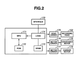
- Fig. 2 is a block diagram showing an exemplary arrangement of a control circuit of the inkjet printer.
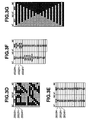
- Figs. 3A through 3G are views showing compression of image data according to a first exemplary embodiment.
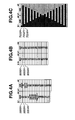
- Figs. 4A through 4C are views showing expansion of image data according to the first exemplary embodiment.
- Figs. 5A through 5C are views showing image data to be recorded according to the first exemplary embodiment.
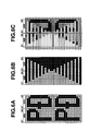
- Figs. 6A through 6F are views showing compression and expansion of image data according to a second exemplary embodiment.
- Figs. 7A through 7C are views showing image data to be recorded according the second exemplary embodiment.
- Fig. 8 is a block diagram showing a printing system including a host apparatus and a recording apparatus according to an exemplary embodiment.
- a first electronic apparatus can transfer image data to a second electronic apparatus.
- the first electronic apparatus has a memory including a region A, a region B, a region C, and a region D.
- the second electronic apparatus has a memory including a region E, a region F, a region G, and a region H.
- the first electronic apparatus can be a host apparatus, and the second electronic apparatus can be a recording apparatus.
- the first electronic apparatus can transfer image data to the recording apparatus.
- the recording apparatus can perform image recording.
- the recording apparatus is, for example, a serial type printer (refer to Fig. 1) which can perform 2-pass recording according to which a recording head repeats a scanning operation twice to form an image at a predetermined region of a recording paper or other recording medium. In this case, the recording head performs scanning in the same direction (i.e., first direction). This scanning operation can be referred to as a unidirectional recording operation.
- Figs. 3A through 3G are views showing compression/expansion patterns and compressed/expanded recording data.
- the recording apparatus performs 2-pass image recording.
- the data transfer system processes recording data in units of a data block consisting of 32 nozzles in the vertical direction x 16 columns in the lateral direction.
- a data volume of 32 rasters x 16 columns constitutes the basic units (size) of recording data.
- the basic units (size) can be a data volume consisting of 32 pixels in a nozzle array direction x 16 pixels in the scanning direction of the recording head.
- the nozzle array direction is a conveyance direction of a recording medium.
- the compression/expansion patterns have the basic units (size) of 32 nozzles in the vertical direction x 16 columns in the lateral direction.
- Fig. 3A illustrates original image data that are not yet subjected to compression.
- Fig. 3A illustrates an exemplary allocation of addresses and an exemplary layout of bits corresponding to an image to be recorded on a recording medium, so that the contents of image data stored in a memory can be easily understood.
- the first electronic apparatus can produce image data of the basic units (or image data exceeding the basic units) beforehand.
- the recording apparatus When the recording apparatus performs a recording operation along the first direction, one pattern “D” is first read out and the other pattern “P” is next read out.
- the recording apparatus first records the pattern “D", as indicated in the region of "00H” shown in Fig. 3A, and next records the pattern "P".
- the recording apparatus In the processing of reading 16-bit data from a memory area of one address, the recording apparatus first processes 8 bits in the "00H” region and next processes 8 bits in a "01H” region.
- the memory of the first electronic apparatus includes a plurality of memory areas allocated to addresses, starting from an address 1000H, in which image data can be successively stored.
- a region where image data can be stored is referred to as region A.
- Each memory area corresponding to one address can store image data of 16 bits.
- a memory area allocated an address can store 16 pixels.
- black circles represent dots to be recorded and white circles represent dots to be unrecorded. Each black circle corresponds to data "1" and each white circle corresponds to data "0.”
- the region A includes plural memory areas divided in the vertical direction to which addresses 1000H, 1002H, 1004H, --- are allocated in this order from the head.
- Fig. 3B illustrates a compression pattern for a first pass.
- the compression pattern can be successively stored in plural memory areas to which addresses 2000H onwards are allocated.
- Fig. 3B illustrates an exemplary allocation of addresses and an exemplary layout of bits corresponding to an image to be recorded on a recording medium, so that the contents of image data stored in a memory can be easily understood.
- a region where the compression pattern can be stored is referred to as region B.
- Each memory area allocated an address can store 16-bits data.
- the first electronic apparatus can use the compression pattern of Fig. 3B to compress the image data shown in Fig. 3A.
- white circles represent dots to be thinned out and black circles represent dots not to be thinned out.
- the total number of black circles is equal to the total number of white circles.
- using the compression pattern of Fig. 3B can reduce the data volume to half the size.
- the region B includes plural divided memory areas to which addresses 2000H, 2002H, 2004H, etc. are allocated in this order from the head.
- Fig. 3C illustrates an exemplary process of compressing original recording data based on the compression pattern shown in Fig. 3B. To simplify description, this processing is hereinafter referred to as compression processing A.
- a region where the compression data can be stored is referred to as region C.
- the compression data can be stored in memory areas to which addresses 3000H, 3002H, 3004H, etc. are allocated.
- the first electronic apparatus can perform compression processing in the following manner. First, the first electronic apparatus can read part of the image data stored in a memory area corresponding to first address (i.e., 1000H) shown in Fig. 3A and part of the compression pattern stored in a memory area corresponding to first address (i.e., 2000H) shown in Fig. 3B. The first electronic apparatus can apply the compression processing A to readout image data of the above address with a readout compression pattern of the above address.
- the first electronic apparatus can store compression result in terms of dots corresponding to black circles with respect to the readout image data of the above address.
- the first electronic apparatus can repeat the above-described processing successively for partial image data and a partial compression pattern corresponding to succeeding addresses (1002H, 2002H; 1004H, 2004H; ------).
- the first electronic apparatus can shift the dots corresponding to black circles toward a lower-bit side. If there is any empty address in the head, the first electronic apparatus can shift the dots upward and can store the dots there.
- the first electronic apparatus reads 16-bit image data out of a memory area of address 1000H.
- the readout image data has a value 0000H.
- the first electronic apparatus reads a 16-bit compression pattern out of a memory area of address 2000H.
- the readout data has a value 8000H.
- the first electronic apparatus applies AND processing to the readout data and pattern to obtain a result of 0000H.
- the readout compression pattern includes only one black circle at the most significant bit (i.e. , only one bit).
- the first electronic apparatus stores 0, as compression data, at b0 in a memory area of address 3000H (i.e., a position corresponding to bit 0).
- the first electronic apparatus reads 16-bit image data out of a memory area of address 1002H.
- the readout data is 7E7CH.
- the first electronic apparatus reads a 16-bit compression pattern out of a memory area of address 2002H.
- the readout data is FFFEH.
- the first electronic apparatus applies AND processing to the readout data and pattern to obtain a result of 7E7CH.
- the compression pattern includes 15 black circles at all bits but the least significant bit.
- the first electronic apparatus stores the 15-bit data at 15 bits starting from b1 in the memory area of address 3000H. While the first electronic apparatus repeats the compression processing A twice, the address 3000H can store 16-bit compression data.
- the first electronic apparatus stores the next compression result in the next memory area of address 3000H starting from b1.
- the first electronic apparatus reads 16-bit image data out of a memory area of address 1004H.
- the readout data is 7F7EH.
- the first electronic apparatus reads a 16-bit compression pattern out of a memory area of address 2004H.
- the readout data is C000H.
- the first electronic apparatus applies AND processing to the readout data and pattern to obtain a result of 4000H.
- the compression pattern includes black circles at the most significant and next bits (i.e., only two bits).
- the first electronic apparatus stores 1 at b0 and 0 at b1, as compression data, in a memory area of address 3002H.
- the first electronic apparatus stores the data of a bit number resulting from the compression processing in units of one bit.
- Fig. 3B illustrates an exemplary layout of 1 bit, 15 bits, 2 bits, and 14 bits. Each arrow shown in Fig. 3C indicates the direction along which the data can be shifted.
- Figs. 3D and 3E show data storage conditions at the end of the compression processing A.
- the first electronic apparatus reads data out of the region C and performs data compression processing in units of 8 bits (hereinafter, refer to as compression processing B) .
- the data units of the compression processing A can be twice the data units of the compression processing B.
- the compression processing B is, for example, a packbit type compression including addition of tag information.
- Fig. 3F illustrates data resulting from the packbit compression and stored in the region D.
- the first electronic apparatus performs the compression processing B in such a manner that, when reception data are successively subjected to expansion (extraction ,decompression) processing, the head data (i.e., first 8-bit data) can be stored in a memory area of address 3000H, the next data (i.e., second 8-bit data) can be stored in a memory area of address 3001H, and the third 8-bit data can be stored in a memory area of address 3002H.
- the head data i.e., first 8-bit data
- the next data i.e., second 8-bit data
- the third 8-bit data can be stored in a memory area of address 3002H.
- the first electronic apparatus stores compression data resulting from the compression processing B in the region D. Furthermore, the first electronic apparatus stores the data resulting from the above-described compression processing A in a predetermined order so as to correspond to the compression order in the later-performed compression processing B (i.e., the data transfer order).
- the first electronic apparatus can transfer a reduced amount of image data to the second electronic apparatus.
- the second electronic apparatus can perform expansion of input image data. As shown in Fig. 4A, the second electronic apparatus can store the input image data in the region E of its memory. Then, the second electronic apparatus can perform expansion processing B corresponding to the above-described compression processing B, and can store expansion data in the region F of its memory as shown in Fig. 4B.
- the second electronic apparatus can store an expansion pattern for the expansion processing B in the memory region G.
- the expansion pattern has a data structure identical to that of the compression pattern.
- the first electronic apparatus can transfer the expansion pattern, and the second electronic apparatus can store the expansion pattern in the memory region G.
- the second electronic apparatus can perform expansion processing A corresponding to the compression processing A, which is applied to the data stored in its memory region F.
- the second electronic apparatus can store the data resulting from the expansion processing in the region H.
- the data in the memory region F are successively stored according to the address order in the memory region A of the first electronic apparatus.
- the second electronic apparatus can store the data successively in memory areas of the region F to which addresses 6000H, etc., are allocated.
- the second electronic apparatus can store the expansion pattern successively in memory areas of the region G to which addresses 7000H, 7002H, 7004H, etc. are allocated.
- the second electronic apparatus reads part of the expansion pattern of one address and part of compressed image data of a corresponding address.
- the second electronic apparatus extracts data of a bit number corresponding to the total number of black circles in the readout expansion pattern, from a lower bit of the compressed image data.
- the second electronic apparatus successively stores the extracted data in bit positions of the black circles.
- the second electronic apparatus repeats the above-described processing.
- the second electronic apparatus reads a partial expansion pattern out of a memory area of address 7000H.
- the readout data value is 8000H. Accordingly, a data number to be extracted from the compression data is 1.
- the second electronic apparatus extracts (obtains) the data of 1 pixel from the compression data.
- the second electronic apparatus reads 16-bit image data of address 6000H (i.e., 16 pixels).
- the readout data is 7E7CH.
- the second electronic apparatus extracts 1 pixel positioned at the least significant bit of the readout data.
- the extracted data is 0.
- the second electronic apparatus applies AND processing to the extracted data and the most significant bit data of the expansion pattern, and obtains a result of 0000H.
- the second electronic apparatus stores the resultant data, as expansion data, in a memory area of head address 8000H in the region H shown in Fig. 5A.
- the memory area of address 8000H stores one white circle at the most significant bit, which is the data (pixel) extracted from the compression data. Neither white circles nor black circles are stored in the rest of the memory area of address 8000H. In the memory area of each address, any vacant area can be regarded as white circles (data is 0).
- the second electronic apparatus reads a partial expansion pattern from a memory area of address 7002H.
- the readout data is FFFEH. Accordingly, the data number to be extracted from the compression data is 15. In other words, the second electronic apparatus extracts (obtains) the data of 15 pixels from the compression data.
- the second electronic apparatus extracts all of remaining 15-bit data of the image data 7E7CH read out in the previous processing.
- the extracted data is 7E7CH.
- the second electronic apparatus applies AND processing to the extracted data and the upper 15 bits of the expansion pattern, and obtains a result of 7E7CH.
- the second electronic apparatus stores the resultant data, as expansion data, in a memory area of address 8002H in the region H.
- the memory area of address 8002H stores neither a white circle nor a black circle at the least significant bit 0, although this area can be regarded as a white circle (data is 0).
- the memory region H can store image data of a recording block, defined as basic units (size), consisting of 32 nozzles in the vertical direction ⁇ 16 columns in the lateral direction.
- the second electronic apparatus receives data of a succeeding recording block and starts a recording operation each time a predetermined amount of data has been received.
- compression processing in a second pass will be described.
- the compression processing in the second pass is similar to the compression processing in the first pass, with the exception of the following points.
- Fig. 3G illustrates a compression pattern for the second pass, which is complementary to the compression pattern shown in Fig. 3B.
- the compression pattern shown in Fig. 3G having a pattern density of 50%, can be used to compress the data in the second pass.
- the compression method for the second pass is similar to the compression method for the first pass. Before performing a recording operation for the second pass, the compression data are transferred.
- expansion processing in the second pass is similar to the expansion processing in the first pass, with the exception of the following points.
- Fig. 3G illustrates an expansion pattern for the second pass.
- the region H stores expansion data for the recording of the data in the second pass, which are successively stored in memory areas of addresses 8000H, 8002H, 8004H, etc..
- an image corresponding to an image size of 32 rasters x 16 columns i.e., 32 nozzles ⁇ 16 columns
- a recording medium as shown in Fig. 5C.
- the second electronic apparatus accesses the memory in units of 16 bits.
- the data resulting from the expansion processing should be prevented from being stored in memory areas of two addresses.
- the recording apparatus i.e., the second electronic apparatus
- the recording apparatus includes the following logic circuit accessing the memory.
- the total number of black circles (data is "1") contained in memory areas of two addresses is always 16. If the two addresses are consecutive, the logic circuit can efficiently access the memory.
- the logic circuit performing the expansion processing can access the memory in units of 32 bits.
- the data transfer system when it performs 3-pass recording, uses compression/expansion patterns different from those used in the 2-pass recording. Furthermore, in the 3-pass recording, the data transfer system accesses the patterns in data units different from that in the 2-pass recording. According to the patterns used in the 3-pass recording, the total number of black circles (data is "1") in memory areas of three addresses (e.g., 7000H, 7002H, and 7004H) is always 16 (including a case where data of 16 bits are "1").
- the logic circuit performing the expansion processing, accesses the memory in units of 48 bits.
- n is an integer equal to or greater than 2.
- the total number of data in memory areas of n addresses should be equal to 16. In other words, 16 bits of effective data should be contained in the memory areas of n addresses.
- the number 16 is equal to the memory access units (bit number) of the recording apparatus which performs the expansion processing A.
- the first electronic apparatus such as an information processing apparatus, selects a compression table based on the value n, and the recording apparatus selects an expansion table based on the value n.
- an image size of 32 rasters ⁇ 16 columns constitutes the basic data units.
- the size (units) of compression data/expansion data is dependent on a recording mode (i.e., a pass number) of each recording apparatus.
- the raster number is equal to a least common multiple of a pass number of the multi-pass recording inherent to each recording apparatus (which performs a unidirectional scanning recording operation plural times at a predetermined region on a recording medium to form an image).
- the data volume transferred from one electronic apparatus to other electronic apparatus can be reduced. The data transfer can be efficiently carried out.
- Fig. 1 is a perspective view showing an inkjet printer as an exemplary electronic apparatus.
- the inkjet printer has the capability of performing both color and monochrome printing functions.
- the inkjet printer can receive data and commands from a personal computer or other host computer, and can perform printing on a recording paper or other recording medium.
- a carriage 101 mounts a multi-nozzle recording head 102 and a cartridge guide 103.
- the recording head 102 can discharge a black (K) ink with 320 nozzles and cyan (C), magenta (M), and yellow (Y) inks with 192 nozzles for each.
- the recording head 102 mounts a monochrome ink cartridge 110 storing the black ink and a color ink cartridge 111 storing the above color inks, so that black (K), cyan (C), magenta (M), and yellow (Y) inks can be respectively supplied from these cartridges.
- a flexible cable including numerous lead wires can supply a drive signal to each nozzle of the recording head 102.
- the carriage 101 is slidably supported on two guide rails 104 and 105.
- An endless belt is connected to the carriage 101.
- the endless belt is driven by a carrier motor (later described)
- the carriage 101 can travel in the X direction (hereinafter, the X direction is referred to as a main scanning direction).
- a conveyance roller 108 when driven by a conveyance motor (later described), can convey a recording paper 106 in the Y direction (hereinafter, the Y direction is referred to as a sub scanning direction).
- Fig. 2 is a block diagram showing an exemplary control circuit for the inkjet printer.
- an interface 170 can input a recording signal from a host computer or other external apparatus.
- An MPU 171 can execute various control programs.
- a ROM 172 can store the control programs (including letter fonts, if necessary).
- An SRAM 173 (or SDRAM, or DRAM) can temporarily store various data (including expansion patterns, and data received from the host apparatus).
- a LOGIC section (ASIC) 174 can control recording performed by the recording head 102, and execute the above-described expansion processing, and HV conversion processing. Furthermore, the LOGIC section 174 can control data transfer among the interface 170, the MPU 171, and the RAM 173.
- a carrier motor 179 can shift the recording head 102 in the main scanning direction.
- a conveyance motor 178 can convey a recording paper.
- a head driver 175 can drive the recording head 102.
- a motor driver 176 can drive the conveyance motor 178.
- Another motor driver 177 can drive the carrier motor 179.
- control circuit can perform the following operations.
- the interface 170 When the interface 170 receives a command and data, the LOGIC 174 and the MPU 171 convert the input data into recording data to be printed.
- the motor drivers 176 and 177 drive the motors 178 and 179, while the head driver 175 drives the recording head 102 based on the received recording data. As a result, an image can be printed on the recording paper 106.
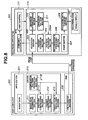
- Fig. 8 is a block diagram showing an exemplary printing system (i.e., a data transfer system) including a host computer and a recording apparatus.
- a printing system i.e., a data transfer system
- the above-described first electronic apparatus is a host computer 200 and the second electronic apparatus is a recording apparatus 300.
- the host computer 200 includes an application 201, a driver 210, and a USB section 220.
- the application 201 can produce image data.
- the driver 210 can produce transfer data based on the image data produced from the application 201.
- the USB section 220 can transfer the transfer data to the recording apparatus 300.
- the driver 210 includes an image data segmenting section (i.e., an image data extracting section, an image data clipping section) 211, a pattern compressing section 211A, a compression pattern producing section 211B, a packbit compressing section 212, and a transfer data producing section 213.
- image data segmenting section i.e., an image data extracting section, an image data clipping section
- the image data segmenting section 211 can obtain (or segment) a predetermined amount of data from the image data produced from the application 201.
- Fig. 3A illustrates an example of segmented data.
- the pattern compressing section 211A can compress the segmented data obtained from the image data segmenting section 211, based on a compression pattern (i.e., compression information, for example shown in Fig. 3B) that the compression pattern producing section 211B can produce.
- Fig. 3D illustrates exemplary compression data.
- the packbit compressing section 212 can further compress the compression data received from the pattern compressing section 211A.
- Fig. 3F illustrates an example of packbit compression data.
- the transfer data producing section 213 can produce transfer data based on the packbit compression data.
- the USB section 220 can receive the transfer data from the transfer data producing section 213 and can output the transfer data via a USB interface to the recording apparatus 300.
- the compression pattern producing section 211B can also send the compression pattern to the transfer data producing section 213.
- the host computer 200 can reduce a data volume transferred to the recording apparatus 300.
- the recording apparatus 300 includes a reception buffer 304 of ASIC 174 that can store the packbit compression data received via the interface from the host 200.
- the ASIC 174 includes a packbit expansion section 305, a pattern expansion section 305A, a recording data producing section 306, a print buffer 307, a recording data transfer section 308, an expansion pattern storage section 310, and an expansion pattern buffer 311.
- the packbit expansion section 305 can expand the packbit compression data stored in the reception buffer 304.
- the pattern expansion section 305A can further expand the compression data expanded in the packbit expansion section 305 based on an expansion pattern.
- the recording data producing section 306 can produce recording data from the expansion data.
- the print buffer 307 can store the recording data produced from the recording data producing section 306.
- the recording data transfer section 308 can read the recording data from the print buffer 307 and transfer the readout recording data to the recording head 102.
- the expansion pattern storage section 310 can read, from the reception buffer 304, the expansion pattern transmitted from the host computer 200.
- the expansion pattern buffer 311 can store the readout expansion pattern, so that the pattern expansion section 305A can read the expansion pattern from the expansion pattern buffer 311.
- the recording apparatus described in the first exemplary embodiment performs a unidirectional 2-pass recording operation, according to which the recording head performs scanning in the same direction.
- a recording apparatus of the second exemplary embodiment can perform a bidirectional or reciprocating 2-pass recording operation, according to which the recording head performs scanning in both a first direction and a second direction opposed to the first direction.
- Fig. 6A illustrates exemplary image data (i.e., original recording data) to be read in the second direction. Because the second direction is opposite to the first direction, the processing order of image data in the second direction is opposite to that in the first direction.
- Fig. 6B illustrates a compression pattern corresponding to the second direction.
- Fig. 6C illustrates a process of compressing the original recording data shown in Fig. 6A based on the compression pattern shown in Fig. 6B. Similar to the processing described in the first exemplary embodiment, the compression process of the second exemplary embodiment includes reading image data from a memory area of one address, reading a compression pattern from a memory area of a corresponding address, and storing compression data from a lower bit side.
- each 16-bit space consists of upper 8 bits and lower 8 bits which are reversed in a positional relationship (i.e., differentiated in the mapping of byte units).
- Fig. 6D illustrates a data storage condition at the end of the compression processing A. These data are further subjected to the compression processing B and are sent to the recording apparatus.
- Fig. 6E illustrates an expansion pattern.
- Fig. 6F illustrates a data storage condition at the end of expansion processing.
- Figs. 7A through 7C illustrate a bidirectional recording operation.
- Fig. 7A illustrates expansion data for the recording of a first pass.
- Fig. 7B illustrates expansion data for the recording of a second pass.
- the expansion data shown in Fig. 7B can be obtained by switching the upper 8 bits and the lower 8 bits in the mapping shown in Fig. 6F.
- Fig. 7C illustrates an image corresponding to an image size of 32 rasters ⁇ 16 columns (i.e., 32 nozzles ⁇ 16 columns) formed on a recording medium.
- the data volume transferred from one electronic apparatus to other electronic apparatus can be reduced.
- the data transfer can be efficiently carried out.
- the data volume transferred from a host apparatus to a recording apparatus can be greatly reduced.
- a printing apparatus performs 2-pass recording, with the resolution of 192 nozzles in the vertical direction and 4800 dpi in the lateral direction, and a data amount transferred at a time is 8 inches in the scanning direction.
- the data amount can be decreased to a half level.
- image data of each recording block has the basic units (size) of 32 nozzles in the vertical direction x 16 columns in the lateral direction.
- the basic units of a recording block can be changed.
- the size of a recording block can be 64 nozzles in the vertical direction x 32 columns in the lateral direction.
- the above-described exemplary embodiments do not intend to limit the data units for the compression processing/expansion processing to be 16 bits. Therefore, the data units for the compression processing/expansion processing can be 32 bits or 64 bits. Furthermore, the above-described exemplary embodiments do not intend to limit the data units in the above-described compression processing A to be twice the data units in the compression processing B. Therefore, the data units in the compression processing A can be 4 times or 8 times the data units in the compression processing B.
- the above-described exemplary embodiments do not intend to limit the first electronic apparatus to a host apparatus which transfers data to the second electronic apparatus and also do not intend to limit the second electronic apparatus to a recording apparatus. Therefore, the first electronic apparatus can be an image input unit (e.g., a scanner), and the second electronic apparatus can be a host apparatus.
- the first electronic apparatus can be an image input unit (e.g., a scanner)
- the second electronic apparatus can be a host apparatus.
- the above exemplary embodiments can be preferably applied to ordinary printing apparatuses of an inkjet recording type, which are equipped with a thermal energy generation unit (e.g., an electrothermal energy conversion member, a laser beam, or the like) to perform ink discharge by controlling the thermal energy that causes conditional changes in the ink.
- a thermal energy generation unit e.g., an electrothermal energy conversion member, a laser beam, or the like
- the printing apparatuses according to the present invention can realize high-density and high-definition recording.
- a recording apparatus is not limited to a printer integrally or separately provided as an image output terminal for a computer or other information processing apparatus, and therefore can be a copying apparatus combined with a reader or a facsimile apparatus having transmission/reception functions.
- the present invention can be applied to a system including plural devices or to a single apparatus. Furthermore, the present invention can be realized by supplying a program to a system or an apparatus.
Landscapes
- Engineering & Computer Science (AREA)
- General Engineering & Computer Science (AREA)
- Physics & Mathematics (AREA)
- General Physics & Mathematics (AREA)
- Theoretical Computer Science (AREA)
- Multimedia (AREA)
- Signal Processing (AREA)
- Computational Linguistics (AREA)
- Record Information Processing For Printing (AREA)
- Ink Jet (AREA)
- Compression, Expansion, Code Conversion, And Decoders (AREA)
Applications Claiming Priority (2)
| Application Number | Priority Date | Filing Date | Title |
|---|---|---|---|
| JP2005159122 | 2005-05-31 | ||
| JP2006120803A JP4435106B2 (ja) | 2005-05-31 | 2006-04-25 | データ転送システム、電子機器 |
Publications (3)
| Publication Number | Publication Date |
|---|---|
| EP1729501A2 true EP1729501A2 (de) | 2006-12-06 |
| EP1729501A3 EP1729501A3 (de) | 2010-08-11 |
| EP1729501B1 EP1729501B1 (de) | 2013-04-17 |
Family
ID=36922240
Family Applications (1)
| Application Number | Title | Priority Date | Filing Date |
|---|---|---|---|
| EP06252703.1A Not-in-force EP1729501B1 (de) | 2005-05-31 | 2006-05-24 | Vorrichtung, Verfahren und Programm zur Informationsverarbeitung |
Country Status (4)
| Country | Link |
|---|---|
| US (1) | US7676098B2 (de) |
| EP (1) | EP1729501B1 (de) |
| JP (1) | JP4435106B2 (de) |
| CN (1) | CN1874408B (de) |
Families Citing this family (4)
| Publication number | Priority date | Publication date | Assignee | Title |
|---|---|---|---|---|
| JP4435106B2 (ja) * | 2005-05-31 | 2010-03-17 | キヤノン株式会社 | データ転送システム、電子機器 |
| US9253505B2 (en) | 2009-04-08 | 2016-02-02 | Newrow, Inc. | System and method for image compression |
| CA2758262C (en) | 2009-04-08 | 2016-09-13 | Watchitoo, Inc. | System and method for image compression |
| JP2016127475A (ja) * | 2015-01-06 | 2016-07-11 | 株式会社リコー | 画像処理システム、画像処理方法、及びプログラム |
Citations (2)
| Publication number | Priority date | Publication date | Assignee | Title |
|---|---|---|---|---|
| JP2005159122A (ja) | 2003-11-27 | 2005-06-16 | Kyocera Corp | 半導体素子収納用パッケージおよび半導体装置 |
| JP2006120803A (ja) | 2004-10-20 | 2006-05-11 | Fujitsu Ltd | 半導体装置及び半導体装置の製造方法 |
Family Cites Families (20)
| Publication number | Priority date | Publication date | Assignee | Title |
|---|---|---|---|---|
| US4568983A (en) * | 1983-12-07 | 1986-02-04 | The Mead Corporation | Image data compression/decompression |
| JPH0728448B2 (ja) * | 1986-02-07 | 1995-03-29 | アールシーエー トムソン ライセンシング コーポレイシヨン | 再構成可能な遠隔制御送信器 |
| DE3706468A1 (de) * | 1987-02-27 | 1988-09-08 | Siemens Ag | Zeichenspeicherverfahren und anordnung zur reduzierung der redundanz von zeichen fuer matrixdrucker mit multipassdruck |
| JP2590899B2 (ja) * | 1987-07-24 | 1997-03-12 | 松下電器産業株式会社 | 文字図形情報表示装置 |
| US6169820B1 (en) * | 1995-09-12 | 2001-01-02 | Tecomac Ag | Data compression process and system for compressing data |
| US6100931A (en) * | 1996-03-19 | 2000-08-08 | Sony Corporation | Method and apparatus for controlling a target amount of code and for compressing video data |
| US5854886A (en) * | 1996-03-29 | 1998-12-29 | Hewlett-Packard Company | Method and system for printing rasterized documents |
| JPH10109433A (ja) | 1996-10-03 | 1998-04-28 | Seiko Epson Corp | プリンタ制御装置及びプリンタ制御方法 |
| US6154233A (en) * | 1999-04-19 | 2000-11-28 | Lexmark International, Inc. | System and method for separating raster data for printing |
| JP4378063B2 (ja) | 2000-05-22 | 2009-12-02 | 株式会社リコー | 画像形成装置 |
| JP2002094992A (ja) * | 2000-09-19 | 2002-03-29 | Sony Corp | 符号化データ長検出装置とその方法および画像符号化装置 |
| JP4646419B2 (ja) * | 2001-02-23 | 2011-03-09 | キヤノン株式会社 | インクジェット記録装置及びインクジェット記録装置の制御方法 |
| US6950974B1 (en) * | 2001-09-07 | 2005-09-27 | Synopsys Inc. | Efficient compression and application of deterministic patterns in a logic BIST architecture |
| JP2003134345A (ja) | 2001-10-25 | 2003-05-09 | Canon Inc | 情報処理方法、情報処理装置、情報処理装置の制御プログラム及び記憶媒体 |
| EP1355265B1 (de) * | 2002-04-15 | 2016-04-13 | Canon Kabushiki Kaisha | Farbendatenpufferung zum Farbdruck |
| US7289243B2 (en) * | 2002-08-07 | 2007-10-30 | Lexmark International, Inc. | Apparatus and method for data compression optimized by print head architecture |
| US7209266B2 (en) * | 2002-12-06 | 2007-04-24 | Kabushiki Kaisha Toshiba | Image processing apparatus |
| KR100686342B1 (ko) * | 2003-11-29 | 2007-02-22 | 삼성에스디아이 주식회사 | 농도구배를 갖는 광전변환층을 구비한 열전사 소자 |
| JP4435106B2 (ja) * | 2005-05-31 | 2010-03-17 | キヤノン株式会社 | データ転送システム、電子機器 |
| JP2006338269A (ja) * | 2005-06-01 | 2006-12-14 | Canon Inc | 記録システム、記録方法、記録装置、及びドライバ |
-
2006
- 2006-04-25 JP JP2006120803A patent/JP4435106B2/ja not_active Expired - Fee Related
- 2006-05-24 EP EP06252703.1A patent/EP1729501B1/de not_active Not-in-force
- 2006-05-25 US US11/420,409 patent/US7676098B2/en not_active Expired - Fee Related
- 2006-05-31 CN CN200610083631.XA patent/CN1874408B/zh not_active Expired - Fee Related
Patent Citations (2)
| Publication number | Priority date | Publication date | Assignee | Title |
|---|---|---|---|---|
| JP2005159122A (ja) | 2003-11-27 | 2005-06-16 | Kyocera Corp | 半導体素子収納用パッケージおよび半導体装置 |
| JP2006120803A (ja) | 2004-10-20 | 2006-05-11 | Fujitsu Ltd | 半導体装置及び半導体装置の製造方法 |
Also Published As
| Publication number | Publication date |
|---|---|
| US20060268164A1 (en) | 2006-11-30 |
| EP1729501B1 (de) | 2013-04-17 |
| JP2007012027A (ja) | 2007-01-18 |
| JP4435106B2 (ja) | 2010-03-17 |
| US7676098B2 (en) | 2010-03-09 |
| CN1874408A (zh) | 2006-12-06 |
| EP1729501A3 (de) | 2010-08-11 |
| CN1874408B (zh) | 2014-03-12 |
Similar Documents
| Publication | Publication Date | Title |
|---|---|---|
| US8724157B2 (en) | Printing apparatus and printer driver | |
| US20070139665A1 (en) | Printing Apparatus, Data Processing Method for Printing Apparatus, and Printing System | |
| US7502139B2 (en) | Image forming apparatus and method, and image forming system | |
| US9135540B2 (en) | Image processing apparatus, image processing method, and program for processing black characters at high resolution | |
| US7676098B2 (en) | Information processing apparatus, system and method for compression of image data | |
| US8004705B2 (en) | Printing system and printing method using transfer of compressed image data and compression pattern from host to printing apparatus | |
| US8134742B2 (en) | Output device and method for outputting density data corresponding to a color material to a printing unit | |
| US7405839B2 (en) | Printing apparatus printer driver, and buffer management method | |
| JP3613076B2 (ja) | 画像処理装置、画像処理方法、および記録媒体 | |
| JP2010012635A (ja) | 記録装置 | |
| US20020044300A1 (en) | Multi-function printer and its control method | |
| US20040227965A1 (en) | Dot data creation process with saved memory capacity | |
| US7377607B2 (en) | Liquid ejecting apparatus and method of transferring image data | |
| JP4641459B2 (ja) | 情報処理装置及びプリンタドライバ | |
| US8068253B2 (en) | Recording apparatus | |
| US8346001B2 (en) | Image processing apparatus, printing apparatus, and image processing method | |
| KR100208385B1 (ko) | 프린터에서 텍스트와 픽쳐데이터를 분리하여 저장하는데이터 버퍼장치 및 방법 | |
| JP3213124B2 (ja) | ファクシミリ装置 | |
| JP3862363B2 (ja) | 情報出力システム及び情報出力方法 | |
| JPH10264454A (ja) | 出力装置及び方法 | |
| JP2007105911A (ja) | 画像処理装置 | |
| JP2006159503A (ja) | インクジェット記録方法 | |
| JP2001225460A (ja) | 印刷時の条件に応じて使用ノズル数を変更する印刷 | |
| JP2007168130A (ja) | 記録装置、画像処理制御装置、及び記録方法 | |
| JPH106575A (ja) | 画像データ処理方法および記憶媒体および画像データ処理装置およびカラープリンタ装置 |
Legal Events
| Date | Code | Title | Description |
|---|---|---|---|
| PUAI | Public reference made under article 153(3) epc to a published international application that has entered the european phase |
Free format text: ORIGINAL CODE: 0009012 |
|
| AK | Designated contracting states |
Kind code of ref document: A2 Designated state(s): AT BE BG CH CY CZ DE DK EE ES FI FR GB GR HU IE IS IT LI LT LU LV MC NL PL PT RO SE SI SK TR |
|
| AX | Request for extension of the european patent |
Extension state: AL BA HR MK YU |
|
| PUAL | Search report despatched |
Free format text: ORIGINAL CODE: 0009013 |
|
| AK | Designated contracting states |
Kind code of ref document: A3 Designated state(s): AT BE BG CH CY CZ DE DK EE ES FI FR GB GR HU IE IS IT LI LT LU LV MC NL PL PT RO SE SI SK TR |
|
| AX | Request for extension of the european patent |
Extension state: AL BA HR MK YU |
|
| RIC1 | Information provided on ipc code assigned before grant |
Ipc: H04N 1/415 20060101ALI20100706BHEP Ipc: H04N 1/413 20060101AFI20060905BHEP Ipc: G06K 15/10 20060101ALI20100706BHEP |
|
| 17P | Request for examination filed |
Effective date: 20110211 |
|
| AKX | Designation fees paid |
Designated state(s): DE FR GB IT |
|
| 17Q | First examination report despatched |
Effective date: 20110620 |
|
| RIC1 | Information provided on ipc code assigned before grant |
Ipc: G06K 15/10 20060101ALI20120924BHEP Ipc: H04N 1/415 20060101ALI20120924BHEP Ipc: H04N 1/413 20060101AFI20120924BHEP |
|
| GRAP | Despatch of communication of intention to grant a patent |
Free format text: ORIGINAL CODE: EPIDOSNIGR1 |
|
| GRAS | Grant fee paid |
Free format text: ORIGINAL CODE: EPIDOSNIGR3 |
|
| GRAA | (expected) grant |
Free format text: ORIGINAL CODE: 0009210 |
|
| AK | Designated contracting states |
Kind code of ref document: B1 Designated state(s): DE FR GB IT |
|
| REG | Reference to a national code |
Ref country code: GB Ref legal event code: FG4D |
|
| REG | Reference to a national code |
Ref country code: DE Ref legal event code: R096 Ref document number: 602006035693 Country of ref document: DE Effective date: 20130613 |
|
| PLBE | No opposition filed within time limit |
Free format text: ORIGINAL CODE: 0009261 |
|
| STAA | Information on the status of an ep patent application or granted ep patent |
Free format text: STATUS: NO OPPOSITION FILED WITHIN TIME LIMIT |
|
| PG25 | Lapsed in a contracting state [announced via postgrant information from national office to epo] |
Ref country code: IT Free format text: LAPSE BECAUSE OF FAILURE TO SUBMIT A TRANSLATION OF THE DESCRIPTION OR TO PAY THE FEE WITHIN THE PRESCRIBED TIME-LIMIT Effective date: 20130417 |
|
| REG | Reference to a national code |
Ref country code: FR Ref legal event code: ST Effective date: 20140131 |
|
| 26N | No opposition filed |
Effective date: 20140120 |
|
| REG | Reference to a national code |
Ref country code: DE Ref legal event code: R097 Ref document number: 602006035693 Country of ref document: DE Effective date: 20140120 |
|
| PG25 | Lapsed in a contracting state [announced via postgrant information from national office to epo] |
Ref country code: FR Free format text: LAPSE BECAUSE OF NON-PAYMENT OF DUE FEES Effective date: 20130617 |
|
| PGFP | Annual fee paid to national office [announced via postgrant information from national office to epo] |
Ref country code: GB Payment date: 20190529 Year of fee payment: 14 Ref country code: DE Payment date: 20190731 Year of fee payment: 14 |
|
| REG | Reference to a national code |
Ref country code: DE Ref legal event code: R119 Ref document number: 602006035693 Country of ref document: DE |
|
| GBPC | Gb: european patent ceased through non-payment of renewal fee |
Effective date: 20200524 |
|
| PG25 | Lapsed in a contracting state [announced via postgrant information from national office to epo] |
Ref country code: GB Free format text: LAPSE BECAUSE OF NON-PAYMENT OF DUE FEES Effective date: 20200524 |
|
| PG25 | Lapsed in a contracting state [announced via postgrant information from national office to epo] |
Ref country code: DE Free format text: LAPSE BECAUSE OF NON-PAYMENT OF DUE FEES Effective date: 20201201 |