EP1730036B2 - Machine et procede a remplir des sacs en vrac a tete mobile - Google Patents
Machine et procede a remplir des sacs en vrac a tete mobile Download PDFInfo
- Publication number
- EP1730036B2 EP1730036B2 EP05732185.3A EP05732185A EP1730036B2 EP 1730036 B2 EP1730036 B2 EP 1730036B2 EP 05732185 A EP05732185 A EP 05732185A EP 1730036 B2 EP1730036 B2 EP 1730036B2
- Authority
- EP
- European Patent Office
- Prior art keywords
- bag
- bulk
- filler
- filling head
- hanging
- Prior art date
- Legal status (The legal status is an assumption and is not a legal conclusion. Google has not performed a legal analysis and makes no representation as to the accuracy of the status listed.)
- Expired - Lifetime
Links
Images






Classifications
-
- B—PERFORMING OPERATIONS; TRANSPORTING
- B65—CONVEYING; PACKING; STORING; HANDLING THIN OR FILAMENTARY MATERIAL
- B65B—MACHINES, APPARATUS OR DEVICES FOR, OR METHODS OF, PACKAGING ARTICLES OR MATERIALS; UNPACKING
- B65B39/00—Nozzles, funnels or guides for introducing articles or materials into containers or wrappers
- B65B39/06—Nozzles, funnels or guides for introducing articles or materials into containers or wrappers adapted to support containers or wrappers
-
- B—PERFORMING OPERATIONS; TRANSPORTING
- B65—CONVEYING; PACKING; STORING; HANDLING THIN OR FILAMENTARY MATERIAL
- B65B—MACHINES, APPARATUS OR DEVICES FOR, OR METHODS OF, PACKAGING ARTICLES OR MATERIALS; UNPACKING
- B65B43/00—Forming, feeding, opening or setting-up containers or receptacles in association with packaging
- B65B43/42—Feeding or positioning bags, boxes, or cartons in the distended, opened, or set-up state; Feeding preformed rigid containers, e.g. tins, capsules, glass tubes, glasses, to the packaging position; Locating containers or receptacles at the filling position; Supporting containers or receptacles during the filling operation
- B65B43/54—Means for supporting containers or receptacles during the filling operation
-
- B—PERFORMING OPERATIONS; TRANSPORTING
- B65—CONVEYING; PACKING; STORING; HANDLING THIN OR FILAMENTARY MATERIAL
- B65B—MACHINES, APPARATUS OR DEVICES FOR, OR METHODS OF, PACKAGING ARTICLES OR MATERIALS; UNPACKING
- B65B1/00—Packaging fluent solid material, e.g. powders, granular or loose fibrous material, loose masses of small articles, in individual containers or receptacles, e.g. bags, sacks, boxes, cartons, cans, or jars
Definitions
- the present invention relates to filling equipment for loading powdered or granular material into bulk bags. More particularly, the present invention relates to a bulk bag filler that allows easy access for an operator to load a new bulk bag to be filled and which allows for easier release and removal of a filled bulk bag.
- FIBCs flexible intermediate bulk containers
- the present invention provides a bulk bag filler having a bag filling head having at least a portion that can be moved from a filling position, in which the bulk bag hanging loops are suspended from hanging loop supports in a position to allow the bulk bag to be filled, to a bag attaching position, in which at least some of the hanging loop supports and the bag spout connection are moved to an operator access position in which the operator can easily reach each the hanging loop supports to attach a bulk bag to be filled.
- the bag filling head has a portion which is repositionable from a filling position, to a bag attaching position in which all of the hanging loop supports are located in an operator access position.
- the hanging loop supports comprise latching mechanisms that provide positive support for the hanging loops in the bag filling position, and can be remotely released to allow a filled bulk bag to be removed. Additionally, the latching mechanisms automatically move the latch to a reset position as the bag filling head moves from the bag filling position to the bag attaching position.
- the invention provides a bag filling head that can be moved vertically to accommodate different size bulk bags and to accommodate different operator positions. Additionally, the height of the bag filling head can be adjusted to an easily accessible height for loading a new bulk bag. This is preferably done in conjunction with the movement of the movable portion of the filling head to a bag attaching position. Additionally, the bag filling head can be moved upwardly as the latching mechanisms are released in order to allow a filled bag to be removed from the bulk bag filler prior to attachment of the next bag to be filled.
- bag attaching position in connection with the position of the moveable portion of the bag filling head for bag attachment refers to a position that can vary from true vertical to within about 35° of true vertical.
- a “side” of the bulk bag filler refers to any of the front, lateral and back areas of the bulk bag filler, as opposed to the top or bottom.
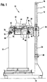
- the bulk bag filler 10 includes a frame 12, having two generally vertically extending posts 14 mounted on a base 16.
- a bag support carriage 20 is connected to the posts 14 utilizing two trolley assemblies 22, which are described in further detail below.
- Lead screw 24 is mounted between a lower support 17 and a top cross piece 26 and engages the support carriage 20.
- a motor 28 is connected to drive the lead screw 24 and can be controlled by a controller to move the support carriage 20 up and down.
- the high position of the support carriage is indicated at 20' in Figure 2 .
- the lead screw 24 is a ball screw which provides for higher speed and lower friction movement of the carriage 20.
- other vertical adjustment means such as pneumatic actuators, a motor and drive belt, a manual crank or any other suitable actuator arrangement could be utilized.
- dust covering bellows (not shown) are attached over the lead screw to prevent the ingress of dust and other contaminants.
- the trolley assemblies 22 each include at least two self aligning roller assemblies 90, and more preferably four self aligning roller assemblies 90, as shown in Figure 6 .
- the roller assemblies 90 include two half rollers 92 mounted on a sleeve 94. As shown in Figure 6 , the outer support 23 of the trolley can be slid inwardly and outwardly prior to being bolted into position so that the rollers 92 are located with their radius firmly against the outer radius of the posts 14. This arrangement allows the half rollers 92 to be positionally adjusted as needed to compensate for variations in tubing width, so that a smooth rolling fit without chatter or binding can be easily achieved.
- upper and lower half rollers 92 are provided on both the front and rear sides of the frame posts 14, so that each trolley 22 includes eight half rollers 92, which are mounted on four separate sleeves 94. While the roller assemblies 90 are preferred, other slide or anti-friction devices and self aligning rollers could be utilized.
- a bag fill head assembly 30 is connected to the bag support carriage 20.
- a bulk material fill tube 32 is connected to the bag fill head 30.
- a gate valve 33 shown in Figure 17A , may be used to control flow of bulk material to the fill tube 32.
- a bag inflation/vacuum port 34 is provided which allows for inflation of an empty bag prior to filling, as well as collection of displaced air and particulates which could otherwise be discharged to atmosphere as the bag is filled. This is preferably connected to a vacuum/blower 35, as shown in Figure 17A .
- the bag filling head assembly 30 includes a base portion 31 and a moveable head portion 40.
- the moveable head 40 includes bag hanging frames 41 on which the hanging loop supports 78 are mounted.
- the moveable portion 40 of the bag filling head 30 can be moved from a filling position, in which the bag hanging loops or straps 60 are suspended from hanging loop supports 78, pivotally mounted on the bag hanging frame 41, in a position to allow the bulk bag 11 to be filled (as shown in Figures 1 and 2 ), to a bag attaching position, in which the hanging loop supports 78 are moved to an operator access position in which the hanging loop supports 78 to attach a bulk bag 11 to be filled are moved to a position in proximity to a side of the bulk bag filler 10 (as shown in Figure 3 ).
- Latch mechanisms 70, 72 are preferably connected to the bag hanging frame 41 to support and release the hanging loop supports 78, as explained in detail below. While a preferred arrangement is shown, various types of hanging loop support arrangements that are mechanically or hydraulically actuated to hold and/or release a bag hanging strap 60 can be utilized.
- repositioning of the moveable head 40 is carried out by a pivotal movement about the two pivots 42 towards the front of the bulk bag discharger 10 utilizing an actuator 44 mounted on the bag filling head 30. This is preferably accomplished by releasing safety latches 46 utilizing release actuators 48, as shown in Figure 4 .
- the actuator 44 is then used to power the moveable head 40 to the position shown in Figure 3 , in which hanging loop supports 78 and the associated front latch mechanisms 70 and rear latch mechanisms 72 are located in the bag attaching position near the front side of the bulk bag filler 10.
- the latches 70, 72 generally define a plane that is within approximately thirty-five (35) degrees or less of true vertical.
- this is within about fifteen (15) degrees of true vertical, and most preferably, the moveable head 40 positions latch mechanisms 70, 72 within about five (5) degrees of vertical to true vertical.
- the angle could be greater up to about sixty (60) degrees from vertical.
- the moveable head 40 pivots toward the front of the bulk bag filler 10, it is also possible that it could pivot toward either lateral side or the rear side, depending on the particular arrangement and application.
- repositioning movement could be carried out by other types of actuators to provide tilting and/or translational movement.
- an inflatable seal assembly 50 is provided for connecting the bag spout to the bulk material fill tube 32.
- the seal assembly 50 including the inflatable seal, is connected to the moveable head assembly 40 and moves therewith to the operator access position to allow for easier connection of the bulk bag 11.
- the inflatable seal 50 includes a top flange 51, which seals against a gasket 52, shown in Figures 3 and 4 , located on base portion 31 of the filling head assembly 30 in order to make a sealed connection with the material fill tube 32.
- a control 54 for the inflatable seal assembly 50 is preferably located on the moveable portion 40 of the bag filling head 30, as shown in Figure 5 . This allows easy access for an operator during installation of a new bulk bag 11.
- connection to the bulk material fill tube 32 is preferably provided in a known typical arrangement with concentric tubes, as shown in Figures 3 and 5 .
- the area between the tubes is utilized for blowing air into the bag via the duct 34 and blower/vacuum 35 for bag inflation, or for withdrawing displaced air from the bag as it is filled to minimize dust.
- the gasket 52 preferably provides a sealed, dust proof connection for both the material fill tube 32 as well as the inflation/vacuum port 34 to the flange 51. This is shown most clearly in Figures 4 and 5 .
- the moveable head release actuator 48 preferably holds the release catch 46 in a closed position.
- two release actuators 48 are utilized to release two separate catches 46.
- the moveable head release actuators 48 are energized.
- the actuator 44 is then actuated in order to drive the moveable head 40 to the bag attaching position as shown in Figure 3 and in Figure 17A .
- safety catch bars 53 on the moveable head 40 shown most clearly in Figure 5 , pull the release catches 46 downwardly so that the moveable head 40 is released and the catches 46 are in a re-latching position.
- the moveable head 40 is retracted via the actuator 44, it pushes the release catches 46 back up to the position where they are reengaged by the release actuators 48, which acts as a safety mechanism.
- latch mechanisms 70, 72 are generally the same with the left and right sides being opposite-handed arrangements of the latch mechanisms 70, 72.
- the latch mechanisms 70, 72 include a support member 74, which is pivotally mounted to a frame member on the moveable head 40 at a first pivot point 103.
- the support member 74 has a first bag loop support arm contacting surface 76 at a first end thereof, which contacts the bag loop supports 78.
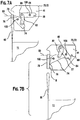
- the bag loop supports 78 are generally L-shaped and pivot about an axis 80, as shown in Figures 7A and 7B .
- a second end of the support member 74 is connected via a pivot link 82 to a first end 86 of a latch member 84.
- the latch member 84 is pivotally mounted at a second pivot point 105 on the frame member of the moveable head 40.
- a latch release pin 88 is connected to an actuator (not shown), which is movable from a first position, in which the latch release pin 88 extends under a second end of the latch member 84, to a second position, away from the latch member 84.
- the latch release pin 88 is movable in a direction generally perpendicular to the latch member 84 and parallel to the axis of the pivots. In the position shown in Figure 7A with the latch release pin in the first position, the latch member 84 is held in a latched horizontal position with the bag loop supports 78 being supported by the first end 76 of the support member 74.
- the latch member 84 is free to pivot about its pivot point due to the weight of the bag strap 60 pulling downwardly on the bag loop supports 78, which contacts the first end 76 of the support member 74, driving the first end 76 of the support member 74 downwardly to release the bag loop supports 78, as well as the bag loop 60 located thereon.
- the bag loop 60 can slide off the end of the bag loop supports 78.
- the second end 77 of the support member 74 contacts the latch member 84 in order to prevent over-travel of the support member 74.
- FIG. 7D this shows the latch mechanism 70, 72 re-oriented after the moveable head 40 has pivoted to the bag attaching position, as shown in Figure 3 .
- gravity acting on the support member 74, pivot link 82 and latch member 84 causes the first end 76 of the support member 74 to move upwardly into a bag loop support 78 engaging position.
- An operator can place a bag strap 60 on the bag loop support 78 and pivot the bag loop supports 78 into a re-latching position, wherein it contacts the first end 76 of the support member 74 and causes it to pivot downwardly, allowing the bag loop support 78 to be moved to the relatched position as shown in Figure 7E .
- the moveable head 40 can be returned to the bag filling position with a new bulk bag 11 ready to be filled.
- a second preferred embodiment of the latch mechanism 170 is shown in Figures 8 - 13 . While only the right hand version of the second embodiment of the latch mechanism 170 is shown, those skilled in the art would understand from the present disclosure that the left hand version for use on the left side of the moveable head portion 40 of the fill head assembly 30 would be a mirror image thereof.
- the latch mechanism 170 includes the support member 174 pivotably mounted to the frame member 201 at a first pivot point 203.
- the first end 176 supports the bag loop support 78.
- the second end 177 of the support member 174 directly contacts the latch member 184 which is also pivotably connected to the frame member 201 at a second pivot point 205.
- a counter-weight 189 is formed on the latch member 184 through an enlarged portion or an added weight.
- the latch release pin 188 is similar to the latch release pin 88 of the latch mechanisms 70, 72.
- the latch mechanism 170 does not require the connecting link as in the first embodiment of the latch mechanism 70, 72, and achieves the same functionality, with the second end 177 of the support member 174 pushing the latch member 184 upwardly when the latch release pin 188 is released, as shown in Figure 9 .
- Gravity acting on the counterweight 189 and on the second end 177 of the support arm 174 results in the resetting and movement to the re-latching position as the latch mechanism 170 is re-oriented by movement of the bag moveable portion of filling head 40 to the bag attaching position, as shown in Figures 10 and 11 .
- a strap 60 from a new bag is placed over the bag loop support arm 78, and it is re-latched, as shown in Figure 13 , preferably by pushing the handle 181, preferably forward integrally with or offered to the support arm 78, toward the latched position, in the direction of stop 211.
- the support arm 174 pivots out of the way for bag loop support arm 78 to pass to the relatched position, and gravity then returns the support arm 174 to the relatched position.
- the bag loop support arm 78 is again supported via the second end 177 of the support arm 174 contacting the latch member 184, which is prevented from rotation via the latch release pin 188.
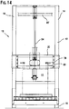
- Figures 14 - 16 show views of the bulk bag filler 10 with the bag support carriage 20 located at different heights, depending upon the size of the bulk bag 11 being filled. This can be easily accomplished by an operator utilizing the moveable lead screw 24 or other vertical adjustment means for the bulk bag filler 10.
- the bulk bag filler 10 is shown with the moveable head 40 in the bag attaching position.
- an operator is shown after placing the tubular bag spout over the inflatable seal assembly 50, which is inflated using the control 54 on the moveable head 40.
- the bag straps 60 have been attached to the latches 70, 72, 170.
- the moveable head 40 is shown returning to the bag filling position after the bulk bag 11 has been attached to the latch mechanisms 70, 72, or 170.
- the bag support carriage 20 has been driven upwardly via the lead screw 24 to the proper height for the bulk bag 11 to be filled. Air can be blown in through the duct 34 by the vacuum/blower 35 in order to inflate the bag prior to filling.
- the inflatable seal 50 which holds the bag spout is deflated, allowing the bag spout to be released from the fill tube connection.
- the latch release pins 88 are moved to a release position, so that the support members 74, 174 of the latch mechanisms 70, 72, 170 are free to pivot.
- the controller signals the drive motor 28 to drive the lead screw 24 in a direction to move the bag support carriage 20 upwardly.
- the weight of the full bag 11 acting through the bag straps 60 pull downwardly on the bag loop supports 78, causing the support members 74, 174 to pivot to the open position, releasing the straps 60.
- the support carriage 20 having moved the bag filling head 30 upwardly and out of the way, the filled bulk bag 11 can be removed using a forklift and/or via sliding it along a roller conveyor to a next position for further handling.
- the bag support carriage 20 moves the bag filling head 30 downwardly.
- the moveable head 40 is preferably rotated about the pivot points 42, by enabling the release actuators 48 and utilizing the actuator 44.
- the movement of the moveable head 40 can be accomplished at the same time as the downward movement of the bag fill head assembly 30 or can be separate movements, depending upon the particular application.
- an operator connects the bag spout of a new bag 11 to be filled to the seal assembly 50 and attaches the four bag straps 60 onto the bag loop supports 78 and resets the bag loop supports 78, preferably by pushing the handles 181, such that the bag loop support 78 are engaged by the support members 74 of the latch mechanisms 70, 72 and 170, as shown in Figure 17A .
- the process repeats, with the moveable head 40 being moved to the bag filling position via the actuator 44 and the release catches 46 being reengaged by the actuators 48, as shown in Figure 17B .
- the lead screw 24 is driven via the drive motor 28 to move the bag filling head 30 to the proper height for the bulk bag 11 being filled.
- a vacuum is drawn through the connection 34 in order to remove displaced air and dust from the bulk bag 11 as it is being filled.
- a dust filter can be provided to allow filtered displaced air to be vented to atmosphere.
- all of the movements of the fill head assembly 30, the moveable head 40, and the associated latches and actuators are controlled by a controller, for example as shown by the operator in Figure 2 , so that movements can be pre-programmed for particular applications, bags sizes, etc.
- a controller for example as shown by the operator in Figure 2 , so that movements can be pre-programmed for particular applications, bags sizes, etc.
- This allows the fill head assembly 30 and the moveable head position 40 to be moved to a convenient position for an operator to attach a new bag and also allows the fill head assembly 30 to be moved upwardly to allow for easy removal of the filled bag prior to repositioning the fill head assembly 30 and the moveable head 40 to the bag attaching position.
- Various controllers such as PLC's, can be used to control the bag filler 10.
Landscapes
- Engineering & Computer Science (AREA)
- Mechanical Engineering (AREA)
- Basic Packing Technique (AREA)
- Supplying Of Containers To The Packaging Station (AREA)
Claims (21)
- Machine de remplissage de sac de vrac (10) destinée à remplir des sacs de vrac (11) présentant des anses de suspension de sac (60) et un bec de remplissage, caractérisée en ce que la machine de remplissage comprend :
une tête de remplissage de sac (30) incluant une partie de base (31) et une partie mobile (40) présentant des supports pour anses (78) et un raccordement pour bec de remplissage de sac (50), la partie mobile (40) pouvant être déplacée d'une position de remplissage de sac, dans laquelle les anses de suspension (60) sont suspendues aux supports pour anses de suspension (78) dans une position permettant de suspendre le sac de vrac (11) en vue d'un remplissage, à une position de fixation de sac, dans laquelle les supports pour anses de suspension (78) pour une fixation d'un sac de vrac (11) et le raccordement pour bec de remplissage de sac (50) sont positionnés à proximité d'un côté de la machine de remplissage de sac (10). - Machine de remplissage de sac de vrac (10) selon la revendication 1, dans lequel la tête de remplissage de sac (30) est montée sur au moins un chariot de support (20) pour un déplacement vers le haut et vers le bas.
- Machine de remplissage de sac de vrac (10) selon la revendication 2, comprenant en outre un actionneur (24) pour un déplacement vers le haut et vers le bas de la tête de remplissage de sac (30).
- Machine de remplissage de sac de vrac (10) selon la revendication 3, dans laquelle l'actionneur (24) est un dispositif de levage actionné par moteur.
- Machine de remplissage de sac de vrac (10) selon la revendication 2, comprenant en outre un cadre (12) doté de deux montants s'étendant verticalement (14), le au moins un chariot de support (20) comprend deux chariots de support (22), un des chariots de support (22) étant relié à chacun des montants (14) pour un déplacement vers le haut et vers le bas de la tête de remplissage de sac (30).
- Machine de remplissage de sac de vrac (10) selon la revendication 1, dans laquelle la partie mobile (40) de la tête de remplissage de sac est montée pour un mouvement de pivotement sur la partie de base (31) de la tête de remplissage de sac (30).
- Machine de remplissage de sac de vrac (10) selon la revendication 1, dans laquelle la partie mobile (40) peut être amenée à pivoter vers une position à proximité d'un côté avant de la machine de remplissage de sac (10).
- Machine de remplissage de sac de vrac (10) selon la revendication 1, comprenant en outre un actionneur (44) monté entre la partie mobile (40) et la partie de base (31) de la tête de remplissage de sac (30) pour un déplacement de la partie mobile (40) de la tête de remplissage de sac (30) entre une position de remplissage de sac et une position de fixation de sac.
- Machine de remplissage de sac de vrac (10) selon la revendication 1, comprenant en outre un raccordement destiné à un tube de remplissage de matériau en vrac (32) situé sur une partie supérieure de la tête de remplissage de sac (30).
- Machine de remplissage de sac de vrac (10) selon la revendication 9, comprenant en outre un ensemble de raccord étanche (50) destiné au bec de remplissage de sac, situé sur la partie mobile (40) de la tête de remplissage de sac (30), et un joint d'étanchéité (52) situé sur la partie de base (31) de la tête de remplissage de sac (30) afin de fournir un raccordement étanche entre le tube de remplissage de matériau en vrac (32) et l'ensemble de raccord étanche (50) lorsque la partie mobile (40) se trouve dans la position de remplissage de sac.
- Machine de remplissage de sac de vrac (10) selon la revendication 10, comprenant en outre un témoin (54) destiné à l'ensemble de raccord étanche (50) situé sur la partie mobile (40) de la tête de remplissage de sac (30).
- Machine de remplissage de sac de vrac (10) selon la revendication 1, comprenant en outre au moins un actionneur de libération d'inclinaison (48) situé sur la tête de remplissage de sac (30) pour déverrouiller la partie mobile (40) de la tête de remplissage de sac (30) pour un déplacement jusqu'à la position de fixation de sac.
- Machine de remplissage de sac de vrac (10) selon la revendication 1, comprenant en outre un dispositif de contrôle pour contrôler un déplacement de la partie mobile (40) de la tête de remplissage de sac (30) et destiné à contrôler un déplacement vers le haut et vers le bas de la tête de remplissage de sac (30).
- Machine de remplissage de sac de vrac selon la revendication 1, dans laquelle la partie mobile (40) comprend un cadre de suspension de sac (41) sur lequel les supports pour anses de suspension (78) et des mécanismes de verrou respectifs (70, 72, 170, 172) sont montés.
- Machine de remplissage de sac de vrac selon la revendication 14, dans laquelle le cadre de suspension de sac (41) peut être amené à pivoter depuis la tête de remplissage de sac autour d'au moins un axe de pivot situé le long d'un côté de la machine de remplissage de sac de vrac (10).
- Machine de remplissage de sac de vrac selon la revendication 1, dans laquelle les supports pour anses de suspension (78) présentent au moins un mécanisme de verrouillage associé (70, 72, 170, 172) comprenant :un élément de support (74, 174) monté avec possibilité de pivotement sur un cadre de verrou au niveau d'une première position de pivotement, et présentant une première surface (76, 176) venant au contact d'un support pour anse de suspension au niveau d'une première extrémité de celui-ci et, au niveau d'une deuxième extrémité de celui-ci, entrant en contact avec une première extrémité d'un élément de verrou (84, 184) qui est monté avec possibilité de pivotement au niveau d'une deuxième position de pivotement,un broche de verrou (88, 188) reliée à un actionneur qui peut être déplacé d'une première position, dans laquelle il s'étend sous une deuxième extrémité de l'élément de verrou (84, 184), à une deuxième position, écartée de l'élément de verrou (84, 184),lorsque la broche de verrou (88, 188) est déplacée jusqu'à la deuxième position, la première extrémité de l'élément de support (74, 174) peut être amenée à pivoter vers le bas pour libérer le support pour anse de sac (78), et lorsque le support pour anse de sac (78) n'est plus en contact avec l'élément de support (74, 174), l'élément de support (74, 174) est équilibré de sorte que la première extrémité pivote vers le haut vers une position de réarmement lorsque le mécanisme de verrouillage (70, 72, 170, 172) est redirigé vers la position de fixation de sac dans laquelle la première extrémité de l'élément de support (74, 174) se trouve dans une position d'engagement de support pour anse de sac, de sorte que le support pour anse de sac (78) peut être amené à pivoter jusque dans une position à nouveau verrouillée en amenant l'élément de support (74, 174) à pivoter hors de la trajectoire du fait que le bras de support est réarmé, et l'élément de support (74) est sollicité par gravité de sorte que la première extrémité retourne à la position à nouveau verrouillée après que la support pour anse de sac (78) retrouve la position à nouveau verrouillée.
- Machine de remplissage de sac de vrac (10) selon la revendication 1, dans laquelle des mécanismes de verrou (70, 72, 170, 172) sont reliés au cadre de suspension de sac (41) de la partie mobile (40) pour supporter et libérer les supports pour anses de sac (78), et dans la position de remplissage de sac, les mécanismes de verrou (70, 72, 170, 172) sont situés dans un plan qui est situé à moins de trente-cinq (35) degrés environ d'une vraie verticale.
- Procédé de chargement d'un sac de vrac (11) présentant des anses de suspension (60) et un bec de remplissage, caractérisé en ce que le procédé comprend :une fourniture d'une machine de remplissage de sac de vrac (10) présentant une tête de remplissage de sac (30) dotée d'une partie de base (31) et d'au moins une partie mobile (40) présentant des supports pour anses (78) dotée d'un raccordement pour bec de remplissage de sac (50), la partie mobile (40) pouvant être déplacée d'une position de remplissage de sac, dans laquelle les anses de suspension sont suspendues aux supports pour anses de suspension (78) dans une position permettant de suspendre le sac de vrac (11) dans une position de remplissage, à une position de fixation de sac, dans laquelle les supports pour anses de suspension (78) pour une fixation d'un sac de vrac à remplir et d'un raccordement pour bec de remplissage de sac (50) sont positionnés à proximité d'un côté de la machine de remplissage de sac (10) ;un déplacement de la partie mobile (40) de la tête de remplissage de sac (30) jusqu'à la position de fixation de sac ;une fixation des anses de suspension de sac (60) aux supports pour anses de suspension (78) situés à proximité du côté de la machine de remplissage de sac ;une fixation du bec de remplissage de sac au raccordement pour bec de remplissage de sac (50) situé à proximité du côté de la machine de remplissage de sac ;un déplacement de la partie mobile (40) de la tête de remplissage de sac (30) jusqu'à la position de remplissage ; etun déchargement de matériau dans le sac de vrac (11) au travers du bec de remplissage de sac.
- Procédé selon 1 revendication 18, comprenant en outre :
un ajustement d'une hauteur de la tête de remplissage de sac (30) jusqu'à une position souhaitée sur base d'une dimension du sac de vrac (11) à remplir. - Procédé selon la revendication 18, comprenant en outre :
un ajustement d'une hauteur de la tête de remplissage de sac (30) jusqu'à une position souhaitée pour une fixation des anses de suspension de sac (60) et du bec de remplissage de sac. - Procédé selon la revendication 18, dans lequel le déplacement de la partie mobile (40) de la tête de remplissage (30) jusqu'à la position de fixation de sac comprend en outre une inclinaison de la partie mobile (40) de la tête de remplissage de sac (30) vers une position dans laquelle les supports pour anses de suspension (78) sont situés dans un plan qui est incliné à moins de trente-cinq (35) degrés de la verticale.
Applications Claiming Priority (2)
| Application Number | Priority Date | Filing Date | Title |
|---|---|---|---|
| US55908504P | 2004-04-02 | 2004-04-02 | |
| PCT/US2005/011436 WO2005097596A1 (fr) | 2004-04-02 | 2005-04-04 | Machine a remplir les sacs de vrac a tete mobile |
Publications (4)
| Publication Number | Publication Date |
|---|---|
| EP1730036A1 EP1730036A1 (fr) | 2006-12-13 |
| EP1730036A4 EP1730036A4 (fr) | 2011-08-24 |
| EP1730036B1 EP1730036B1 (fr) | 2013-07-10 |
| EP1730036B2 true EP1730036B2 (fr) | 2021-05-19 |
Family
ID=35124946
Family Applications (1)
| Application Number | Title | Priority Date | Filing Date |
|---|---|---|---|
| EP05732185.3A Expired - Lifetime EP1730036B2 (fr) | 2004-04-02 | 2005-04-04 | Machine et procede a remplir des sacs en vrac a tete mobile |
Country Status (8)
| Country | Link |
|---|---|
| US (1) | US7004212B2 (fr) |
| EP (1) | EP1730036B2 (fr) |
| AU (1) | AU2005231833B2 (fr) |
| CA (1) | CA2561780C (fr) |
| DK (1) | DK1730036T4 (fr) |
| ES (1) | ES2427424T5 (fr) |
| NZ (1) | NZ550337A (fr) |
| WO (1) | WO2005097596A1 (fr) |
Families Citing this family (15)
| Publication number | Priority date | Publication date | Assignee | Title |
|---|---|---|---|---|
| US7267145B2 (en) * | 2004-05-03 | 2007-09-11 | Material Transfer & Storage, Inc. | Bulk bag filling system |
| US7267144B2 (en) * | 2004-05-03 | 2007-09-11 | Material Transfer & Storage, Inc. | Bulk bag filling system |
| DE102005011813A1 (de) * | 2005-03-15 | 2006-09-21 | Nordenia Deutschland Emsdetten Gmbh | Flexibler Behälter und Vorrichtung zum Befüllen eines flexiblen Behälters |
| WO2007028251A1 (fr) * | 2005-09-09 | 2007-03-15 | Control And Metering Limited | Appareil d'ensachage modulaire |
| US8528606B1 (en) | 2007-11-14 | 2013-09-10 | Michael J. Seiver | Apparatus and methods for filling containers with non-liquids |
| CA2752085C (fr) * | 2009-02-24 | 2015-08-18 | Gala Industries, Inc. | Procedes et systemes d'ensachage continu |
| US9925694B2 (en) | 2009-02-24 | 2018-03-27 | Gala Industries, Inc. | Continuous bagging processes and systems |
| DE102011105969A1 (de) * | 2011-06-29 | 2013-01-03 | Emde Industrie-Technik Gesellschaft für Rationalisierung und Verfahrenstechnik mbH | Aufnahmeanordnung für die automatisierte Handhabung von Großsäcken (Big Bags) |
| ITVI20110208A1 (it) * | 2011-07-28 | 2013-01-29 | Trade Pack S P A | Impianto per il riempimento di sacchi a bretella |
| ITVI20120126A1 (it) * | 2012-05-30 | 2013-12-01 | Trade Pack S P A | Impianto per il riempimento di sacchi a bretella |
| FR3027595A1 (fr) * | 2014-10-24 | 2016-04-29 | Sofraden Ind | Distributeur pour grand recipient vrac souple |
| DK179045B1 (da) * | 2016-02-17 | 2017-09-18 | Panpac Eng As | Fremgangsmåde til justering af anlæg for fyldning af storsække, samt anlæg til fyldning af storsække |
| CN113511381B (zh) * | 2021-07-14 | 2023-05-23 | 马玉彪 | 一种用于谷物包装的麻袋夹紧器 |
| CN114715449B (zh) * | 2022-04-18 | 2022-11-18 | 兴化市三圆锌品有限公司 | 一种氧化锌自动装袋设备 |
| CN116873448B (zh) * | 2023-09-05 | 2024-02-02 | 四川富临新能源科技有限公司 | 一种锂电正极材料生产的原料自动配送投料系统及方法 |
Citations (5)
| Publication number | Priority date | Publication date | Assignee | Title |
|---|---|---|---|---|
| ATE67742T1 (de) † | 1987-06-05 | 1991-10-15 | Custom Packaging Syst | Flexibler grosssack und verfahren zu seiner herstellung. |
| US5165455A (en) † | 1991-04-29 | 1992-11-24 | Crane Charles E De | Method for hanging a bulk unfilled bag on latches of a bag filling machine |
| DE29608328U1 (de) † | 1996-05-08 | 1996-09-05 | Greif-Werk Maschinenfabrik GmbH, 23560 Lübeck | Anhängvorrichtung für FIBC |
| DE19618534A1 (de) † | 1996-05-08 | 1997-11-13 | Greif Velox Maschf Gmbh | Anhängvorrichtung für FIBC |
| EP1319599A1 (fr) † | 2001-12-13 | 2003-06-18 | Firma Haver & Boecker | Dispositif pour remplir des gros sacs ouverts |
Family Cites Families (21)
| Publication number | Priority date | Publication date | Assignee | Title |
|---|---|---|---|---|
| US1909670A (en) | 1931-06-29 | 1933-05-16 | David A Evans | Sacking device |
| US2950589A (en) | 1958-07-31 | 1960-08-30 | Litchard Alexander | Bag feeding mechanism |
| US3225514A (en) | 1960-11-15 | 1965-12-28 | Inglett & Company Inc | Automatic bag-hanging and bag-filling apparatus |
| US3225515A (en) | 1963-04-09 | 1965-12-28 | Wilfred L Inglett | Automatic bag hanger |
| IT995630B (it) | 1973-10-05 | 1975-11-20 | Buzzi R | Macchina per riempire e cucire automaticamente sacchi |
| US4078358A (en) | 1976-08-31 | 1978-03-14 | National Distillers And Chemical Corporation | Bag-hanging and bag-filling machines adapted for synchronous and independent operation and method of using same |
| US4182094A (en) | 1978-03-15 | 1980-01-08 | Bemis Company, Inc. | Bag opening and filling apparatus |
| DE2821273C2 (de) | 1978-05-16 | 1985-07-25 | Windmöller & Hölscher, 4540 Lengerich | Vorrichtung zum Anhängen von Großsäcken an den Fülltrichter einer Sackfüllvorrichtung |
| US4211053A (en) | 1978-10-06 | 1980-07-08 | Niccolls Peter J | Machines for applying bags or sacks to the discharge spouts of bag-filling machines |
| US5056571A (en) | 1989-06-12 | 1991-10-15 | Super Sack Manufacturing Company | Container fill system |
| US5036893A (en) * | 1990-03-23 | 1991-08-06 | Decrane Charles E | Bag filling machine with traversing latch mechanism |
| US5337541A (en) | 1991-01-26 | 1994-08-16 | Buehler Ag | Method for the automatic supply of bags and bag hanging apparatus |
| US5222535A (en) | 1991-11-22 | 1993-06-29 | Roders George W | Bag holding device |
| US5400837A (en) * | 1993-11-04 | 1995-03-28 | Stone Container Corporation | Multi-station filling apparatus and process for filling bulk containers |
| US5787945A (en) * | 1996-05-07 | 1998-08-04 | National Bulk Equipment, Inc. | Bulk bag support for filling |
| CA2204309A1 (fr) | 1997-05-02 | 1998-11-02 | Salvatore Nicastro | Machine de remplissage et de scellage de sacs |
| JP2002173112A (ja) | 2000-12-06 | 2002-06-18 | Toyo Jidoki Co Ltd | 自動包装機の給袋装置 |
| US6374874B1 (en) | 2001-06-22 | 2002-04-23 | Robert W. Payne | Sand bag loading system |
| GB0122548D0 (en) | 2001-09-19 | 2001-11-07 | Flomat Bagfilla Internat Ltd | Bag filling apparatus |
| GB2387588B (en) | 2002-04-19 | 2005-09-14 | Webster Griffin Ltd | A method of filling a bag and an apparatus for filling a bag |
| US6776197B1 (en) * | 2002-09-12 | 2004-08-17 | Decrane Charles E | Method and apparatus for a traversing filler spout for solid bulk bag filling station |
-
2005
- 2005-04-04 ES ES05732185T patent/ES2427424T5/es not_active Expired - Lifetime
- 2005-04-04 EP EP05732185.3A patent/EP1730036B2/fr not_active Expired - Lifetime
- 2005-04-04 CA CA002561780A patent/CA2561780C/fr not_active Expired - Lifetime
- 2005-04-04 NZ NZ550337A patent/NZ550337A/en not_active IP Right Cessation
- 2005-04-04 US US11/098,277 patent/US7004212B2/en not_active Expired - Lifetime
- 2005-04-04 WO PCT/US2005/011436 patent/WO2005097596A1/fr not_active Ceased
- 2005-04-04 DK DK05732185.3T patent/DK1730036T4/da active
- 2005-04-04 AU AU2005231833A patent/AU2005231833B2/en not_active Ceased
Patent Citations (5)
| Publication number | Priority date | Publication date | Assignee | Title |
|---|---|---|---|---|
| ATE67742T1 (de) † | 1987-06-05 | 1991-10-15 | Custom Packaging Syst | Flexibler grosssack und verfahren zu seiner herstellung. |
| US5165455A (en) † | 1991-04-29 | 1992-11-24 | Crane Charles E De | Method for hanging a bulk unfilled bag on latches of a bag filling machine |
| DE29608328U1 (de) † | 1996-05-08 | 1996-09-05 | Greif-Werk Maschinenfabrik GmbH, 23560 Lübeck | Anhängvorrichtung für FIBC |
| DE19618534A1 (de) † | 1996-05-08 | 1997-11-13 | Greif Velox Maschf Gmbh | Anhängvorrichtung für FIBC |
| EP1319599A1 (fr) † | 2001-12-13 | 2003-06-18 | Firma Haver & Boecker | Dispositif pour remplir des gros sacs ouverts |
Also Published As
| Publication number | Publication date |
|---|---|
| ES2427424T3 (es) | 2013-10-30 |
| ES2427424T5 (es) | 2021-11-26 |
| CA2561780A1 (fr) | 2005-10-20 |
| DK1730036T3 (da) | 2013-09-16 |
| AU2005231833B2 (en) | 2009-02-26 |
| EP1730036B1 (fr) | 2013-07-10 |
| US7004212B2 (en) | 2006-02-28 |
| CA2561780C (fr) | 2009-07-14 |
| DK1730036T4 (da) | 2021-08-23 |
| US20050217754A1 (en) | 2005-10-06 |
| EP1730036A4 (fr) | 2011-08-24 |
| WO2005097596A1 (fr) | 2005-10-20 |
| NZ550337A (en) | 2009-05-31 |
| AU2005231833A1 (en) | 2005-10-20 |
| EP1730036A1 (fr) | 2006-12-13 |
Similar Documents
| Publication | Publication Date | Title |
|---|---|---|
| EP1730036B2 (fr) | Machine et procede a remplir des sacs en vrac a tete mobile | |
| US4676284A (en) | Bag filling machine with releaseable supporting arms | |
| US5787945A (en) | Bulk bag support for filling | |
| US6176278B1 (en) | Bulk bag holder | |
| EP0002875A1 (fr) | Procédé et appareil pour le remplissage de récipients avec des articles tels que des paquets postaux | |
| US7267145B2 (en) | Bulk bag filling system | |
| JP2025511763A (ja) | 輸送バッグ、支持フック、輸送装置及びオーバーヘッドコンベヤシステム | |
| US7267144B2 (en) | Bulk bag filling system | |
| US6089285A (en) | Method and system for supplying semiconductor source material | |
| JP5856251B2 (ja) | テールゲートリフタ装置 | |
| US11598138B2 (en) | Barge lid grain door opening apparatus | |
| TWM657465U (zh) | 抖袋機吊鈎模組水平位移控制裝置 | |
| EP1251088B1 (fr) | Dispositif pour vider un fût | |
| CN218534707U (zh) | 烟梗烟袋分离装置 | |
| CN110505981B (zh) | 用于接收并运输部件、特别是软管或配管的设备、用于车辆的材料收集容器以及具有这种设备的吸泥车 | |
| CN216037450U (zh) | 辅助卸料设备 | |
| BE1028782B1 (nl) | Installatie voor het lossen van een bulkgoed uit een vaartuig | |
| CN222005576U (zh) | 一种物料包装袋自动上袋装置 | |
| CN221894211U (zh) | 一种防止货物倾倒的装车机器人装车结构 | |
| CN220011254U (zh) | 码垛自动上下料系统及其自动补偿式机械手 | |
| CN216424956U (zh) | 全自动吨袋包装生产线 | |
| JP2005187181A (ja) | 昇降作業機 | |
| CN110937386A (zh) | 运输设备 | |
| JPH0256474B2 (fr) | ||
| JP2000238702A (ja) | 粉体充填システム |
Legal Events
| Date | Code | Title | Description |
|---|---|---|---|
| PUAI | Public reference made under article 153(3) epc to a published international application that has entered the european phase |
Free format text: ORIGINAL CODE: 0009012 |
|
| 17P | Request for examination filed |
Effective date: 20061014 |
|
| AK | Designated contracting states |
Kind code of ref document: A1 Designated state(s): AT BE BG CH CY CZ DE DK EE ES FI FR GB GR HU IE IS IT LI LT LU MC NL PL PT RO SE SI SK TR |
|
| DAX | Request for extension of the european patent (deleted) | ||
| A4 | Supplementary search report drawn up and despatched |
Effective date: 20110721 |
|
| RIC1 | Information provided on ipc code assigned before grant |
Ipc: B65B 43/46 20060101ALI20110715BHEP Ipc: B65B 1/04 20060101AFI20110715BHEP Ipc: B65B 69/00 20060101ALI20110715BHEP |
|
| 17Q | First examination report despatched |
Effective date: 20120814 |
|
| GRAP | Despatch of communication of intention to grant a patent |
Free format text: ORIGINAL CODE: EPIDOSNIGR1 |
|
| GRAS | Grant fee paid |
Free format text: ORIGINAL CODE: EPIDOSNIGR3 |
|
| GRAA | (expected) grant |
Free format text: ORIGINAL CODE: 0009210 |
|
| AK | Designated contracting states |
Kind code of ref document: B1 Designated state(s): AT BE BG CH CY CZ DE DK EE ES FI FR GB GR HU IE IS IT LI LT LU MC NL PL PT RO SE SI SK TR |
|
| REG | Reference to a national code |
Ref country code: GB Ref legal event code: FG4D |
|
| REG | Reference to a national code |
Ref country code: AT Ref legal event code: REF Ref document number: 620818 Country of ref document: AT Kind code of ref document: T Effective date: 20130715 Ref country code: CH Ref legal event code: EP |
|
| REG | Reference to a national code |
Ref country code: IE Ref legal event code: FG4D |
|
| REG | Reference to a national code |
Ref country code: DE Ref legal event code: R096 Ref document number: 602005040336 Country of ref document: DE Effective date: 20130829 |
|
| REG | Reference to a national code |
Ref country code: DK Ref legal event code: T3 |
|
| REG | Reference to a national code |
Ref country code: NL Ref legal event code: T3 |
|
| REG | Reference to a national code |
Ref country code: SE Ref legal event code: TRGR |
|
| REG | Reference to a national code |
Ref country code: ES Ref legal event code: FG2A Ref document number: 2427424 Country of ref document: ES Kind code of ref document: T3 Effective date: 20131030 |
|
| PG25 | Lapsed in a contracting state [announced via postgrant information from national office to epo] |
Ref country code: SI Free format text: LAPSE BECAUSE OF FAILURE TO SUBMIT A TRANSLATION OF THE DESCRIPTION OR TO PAY THE FEE WITHIN THE PRESCRIBED TIME-LIMIT Effective date: 20130710 |
|
| REG | Reference to a national code |
Ref country code: AT Ref legal event code: MK05 Ref document number: 620818 Country of ref document: AT Kind code of ref document: T Effective date: 20130710 |
|
| REG | Reference to a national code |
Ref country code: LT Ref legal event code: MG4D |
|
| PG25 | Lapsed in a contracting state [announced via postgrant information from national office to epo] |
Ref country code: AT Free format text: LAPSE BECAUSE OF FAILURE TO SUBMIT A TRANSLATION OF THE DESCRIPTION OR TO PAY THE FEE WITHIN THE PRESCRIBED TIME-LIMIT Effective date: 20130710 Ref country code: PT Free format text: LAPSE BECAUSE OF FAILURE TO SUBMIT A TRANSLATION OF THE DESCRIPTION OR TO PAY THE FEE WITHIN THE PRESCRIBED TIME-LIMIT Effective date: 20131111 Ref country code: CY Free format text: LAPSE BECAUSE OF FAILURE TO SUBMIT A TRANSLATION OF THE DESCRIPTION OR TO PAY THE FEE WITHIN THE PRESCRIBED TIME-LIMIT Effective date: 20130710 Ref country code: LT Free format text: LAPSE BECAUSE OF FAILURE TO SUBMIT A TRANSLATION OF THE DESCRIPTION OR TO PAY THE FEE WITHIN THE PRESCRIBED TIME-LIMIT Effective date: 20130710 Ref country code: IS Free format text: LAPSE BECAUSE OF FAILURE TO SUBMIT A TRANSLATION OF THE DESCRIPTION OR TO PAY THE FEE WITHIN THE PRESCRIBED TIME-LIMIT Effective date: 20131110 |
|
| PG25 | Lapsed in a contracting state [announced via postgrant information from national office to epo] |
Ref country code: FI Free format text: LAPSE BECAUSE OF FAILURE TO SUBMIT A TRANSLATION OF THE DESCRIPTION OR TO PAY THE FEE WITHIN THE PRESCRIBED TIME-LIMIT Effective date: 20130710 Ref country code: GR Free format text: LAPSE BECAUSE OF FAILURE TO SUBMIT A TRANSLATION OF THE DESCRIPTION OR TO PAY THE FEE WITHIN THE PRESCRIBED TIME-LIMIT Effective date: 20131011 Ref country code: PL Free format text: LAPSE BECAUSE OF FAILURE TO SUBMIT A TRANSLATION OF THE DESCRIPTION OR TO PAY THE FEE WITHIN THE PRESCRIBED TIME-LIMIT Effective date: 20130710 |
|
| PLBI | Opposition filed |
Free format text: ORIGINAL CODE: 0009260 |
|
| PG25 | Lapsed in a contracting state [announced via postgrant information from national office to epo] |
Ref country code: EE Free format text: LAPSE BECAUSE OF FAILURE TO SUBMIT A TRANSLATION OF THE DESCRIPTION OR TO PAY THE FEE WITHIN THE PRESCRIBED TIME-LIMIT Effective date: 20130710 Ref country code: SK Free format text: LAPSE BECAUSE OF FAILURE TO SUBMIT A TRANSLATION OF THE DESCRIPTION OR TO PAY THE FEE WITHIN THE PRESCRIBED TIME-LIMIT Effective date: 20130710 Ref country code: CZ Free format text: LAPSE BECAUSE OF FAILURE TO SUBMIT A TRANSLATION OF THE DESCRIPTION OR TO PAY THE FEE WITHIN THE PRESCRIBED TIME-LIMIT Effective date: 20130710 Ref country code: RO Free format text: LAPSE BECAUSE OF FAILURE TO SUBMIT A TRANSLATION OF THE DESCRIPTION OR TO PAY THE FEE WITHIN THE PRESCRIBED TIME-LIMIT Effective date: 20130710 |
|
| 26 | Opposition filed |
Opponent name: HAVER & BOECKER OHG Effective date: 20140410 |
|
| PLAX | Notice of opposition and request to file observation + time limit sent |
Free format text: ORIGINAL CODE: EPIDOSNOBS2 |
|
| REG | Reference to a national code |
Ref country code: DE Ref legal event code: R026 Ref document number: 602005040336 Country of ref document: DE Effective date: 20140410 |
|
| PLBB | Reply of patent proprietor to notice(s) of opposition received |
Free format text: ORIGINAL CODE: EPIDOSNOBS3 |
|
| PLAB | Opposition data, opponent's data or that of the opponent's representative modified |
Free format text: ORIGINAL CODE: 0009299OPPO |
|
| R26 | Opposition filed (corrected) |
Opponent name: HAVER & BOECKER OHG Effective date: 20140410 |
|
| PG25 | Lapsed in a contracting state [announced via postgrant information from national office to epo] |
Ref country code: MC Free format text: LAPSE BECAUSE OF FAILURE TO SUBMIT A TRANSLATION OF THE DESCRIPTION OR TO PAY THE FEE WITHIN THE PRESCRIBED TIME-LIMIT Effective date: 20130710 Ref country code: LU Free format text: LAPSE BECAUSE OF FAILURE TO SUBMIT A TRANSLATION OF THE DESCRIPTION OR TO PAY THE FEE WITHIN THE PRESCRIBED TIME-LIMIT Effective date: 20140404 |
|
| REG | Reference to a national code |
Ref country code: CH Ref legal event code: PL |
|
| REG | Reference to a national code |
Ref country code: IE Ref legal event code: MM4A |
|
| PG25 | Lapsed in a contracting state [announced via postgrant information from national office to epo] |
Ref country code: CH Free format text: LAPSE BECAUSE OF NON-PAYMENT OF DUE FEES Effective date: 20140430 Ref country code: LI Free format text: LAPSE BECAUSE OF NON-PAYMENT OF DUE FEES Effective date: 20140430 |
|
| REG | Reference to a national code |
Ref country code: FR Ref legal event code: PLFP Year of fee payment: 11 |
|
| PG25 | Lapsed in a contracting state [announced via postgrant information from national office to epo] |
Ref country code: IE Free format text: LAPSE BECAUSE OF NON-PAYMENT OF DUE FEES Effective date: 20140404 |
|
| PLAY | Examination report in opposition despatched + time limit |
Free format text: ORIGINAL CODE: EPIDOSNORE2 |
|
| PLAH | Information related to despatch of examination report in opposition + time limit modified |
Free format text: ORIGINAL CODE: EPIDOSCORE2 |
|
| PLAT | Information related to reply to examination report in opposition deleted |
Free format text: ORIGINAL CODE: EPIDOSDORE3 |
|
| PLBC | Reply to examination report in opposition received |
Free format text: ORIGINAL CODE: EPIDOSNORE3 |
|
| PLBC | Reply to examination report in opposition received |
Free format text: ORIGINAL CODE: EPIDOSNORE3 |
|
| REG | Reference to a national code |
Ref country code: FR Ref legal event code: PLFP Year of fee payment: 12 |
|
| PG25 | Lapsed in a contracting state [announced via postgrant information from national office to epo] |
Ref country code: BG Free format text: LAPSE BECAUSE OF FAILURE TO SUBMIT A TRANSLATION OF THE DESCRIPTION OR TO PAY THE FEE WITHIN THE PRESCRIBED TIME-LIMIT Effective date: 20130710 |
|
| PG25 | Lapsed in a contracting state [announced via postgrant information from national office to epo] |
Ref country code: TR Free format text: LAPSE BECAUSE OF FAILURE TO SUBMIT A TRANSLATION OF THE DESCRIPTION OR TO PAY THE FEE WITHIN THE PRESCRIBED TIME-LIMIT Effective date: 20130710 Ref country code: HU Free format text: LAPSE BECAUSE OF FAILURE TO SUBMIT A TRANSLATION OF THE DESCRIPTION OR TO PAY THE FEE WITHIN THE PRESCRIBED TIME-LIMIT; INVALID AB INITIO Effective date: 20050404 |
|
| PLBP | Opposition withdrawn |
Free format text: ORIGINAL CODE: 0009264 |
|
| RIC2 | Information provided on ipc code assigned after grant |
Ipc: B65B 1/00 20060101ALN20170209BHEP Ipc: B65B 43/54 20060101ALI20170209BHEP Ipc: B65B 39/06 20060101AFI20170209BHEP |
|
| APBM | Appeal reference recorded |
Free format text: ORIGINAL CODE: EPIDOSNREFNO |
|
| APBP | Date of receipt of notice of appeal recorded |
Free format text: ORIGINAL CODE: EPIDOSNNOA2O |
|
| REG | Reference to a national code |
Ref country code: FR Ref legal event code: PLFP Year of fee payment: 13 |
|
| APBQ | Date of receipt of statement of grounds of appeal recorded |
Free format text: ORIGINAL CODE: EPIDOSNNOA3O |
|
| APAH | Appeal reference modified |
Free format text: ORIGINAL CODE: EPIDOSCREFNO |
|
| REG | Reference to a national code |
Ref country code: FR Ref legal event code: PLFP Year of fee payment: 14 |
|
| APBY | Invitation to file observations in appeal sent |
Free format text: ORIGINAL CODE: EPIDOSNOBA2O |
|
| APBU | Appeal procedure closed |
Free format text: ORIGINAL CODE: EPIDOSNNOA9O |
|
| PUAH | Patent maintained in amended form |
Free format text: ORIGINAL CODE: 0009272 |
|
| STAA | Information on the status of an ep patent application or granted ep patent |
Free format text: STATUS: PATENT MAINTAINED AS AMENDED |
|
| 27A | Patent maintained in amended form |
Effective date: 20210519 |
|
| AK | Designated contracting states |
Kind code of ref document: B2 Designated state(s): AT BE BG CH CY CZ DE DK EE ES FI FR GB GR HU IE IS IT LI LT LU MC NL PL PT RO SE SI SK TR |
|
| REG | Reference to a national code |
Ref country code: DE Ref legal event code: R102 Ref document number: 602005040336 Country of ref document: DE |
|
| REG | Reference to a national code |
Ref country code: NL Ref legal event code: FP |
|
| REG | Reference to a national code |
Ref country code: DK Ref legal event code: T4 Effective date: 20210818 |
|
| REG | Reference to a national code |
Ref country code: SE Ref legal event code: RPEO |
|
| REG | Reference to a national code |
Ref country code: ES Ref legal event code: DC2A Ref document number: 2427424 Country of ref document: ES Kind code of ref document: T5 Effective date: 20211126 |
|
| PGFP | Annual fee paid to national office [announced via postgrant information from national office to epo] |
Ref country code: NL Payment date: 20220420 Year of fee payment: 18 |
|
| PGFP | Annual fee paid to national office [announced via postgrant information from national office to epo] |
Ref country code: SE Payment date: 20220411 Year of fee payment: 18 Ref country code: IT Payment date: 20220412 Year of fee payment: 18 Ref country code: GB Payment date: 20220407 Year of fee payment: 18 Ref country code: FR Payment date: 20220408 Year of fee payment: 18 Ref country code: ES Payment date: 20220504 Year of fee payment: 18 Ref country code: DK Payment date: 20220412 Year of fee payment: 18 Ref country code: DE Payment date: 20220406 Year of fee payment: 18 |
|
| PGFP | Annual fee paid to national office [announced via postgrant information from national office to epo] |
Ref country code: BE Payment date: 20220420 Year of fee payment: 18 |
|
| REG | Reference to a national code |
Ref country code: DE Ref legal event code: R119 Ref document number: 602005040336 Country of ref document: DE |
|
| REG | Reference to a national code |
Ref country code: DK Ref legal event code: EBP Effective date: 20230430 |
|
| REG | Reference to a national code |
Ref country code: SE Ref legal event code: EUG |
|
| REG | Reference to a national code |
Ref country code: NL Ref legal event code: MM Effective date: 20230501 |
|
| GBPC | Gb: european patent ceased through non-payment of renewal fee |
Effective date: 20230404 |
|
| REG | Reference to a national code |
Ref country code: BE Ref legal event code: MM Effective date: 20230430 |
|
| PG25 | Lapsed in a contracting state [announced via postgrant information from national office to epo] |
Ref country code: GB Free format text: LAPSE BECAUSE OF NON-PAYMENT OF DUE FEES Effective date: 20230404 |
|
| PG25 | Lapsed in a contracting state [announced via postgrant information from national office to epo] |
Ref country code: SE Free format text: LAPSE BECAUSE OF NON-PAYMENT OF DUE FEES Effective date: 20230405 Ref country code: NL Free format text: LAPSE BECAUSE OF NON-PAYMENT OF DUE FEES Effective date: 20230501 Ref country code: GB Free format text: LAPSE BECAUSE OF NON-PAYMENT OF DUE FEES Effective date: 20230404 Ref country code: FR Free format text: LAPSE BECAUSE OF NON-PAYMENT OF DUE FEES Effective date: 20230430 Ref country code: DE Free format text: LAPSE BECAUSE OF NON-PAYMENT OF DUE FEES Effective date: 20231103 |
|
| PG25 | Lapsed in a contracting state [announced via postgrant information from national office to epo] |
Ref country code: BE Free format text: LAPSE BECAUSE OF NON-PAYMENT OF DUE FEES Effective date: 20230430 |
|
| PG25 | Lapsed in a contracting state [announced via postgrant information from national office to epo] |
Ref country code: IT Free format text: LAPSE BECAUSE OF NON-PAYMENT OF DUE FEES Effective date: 20230404 Ref country code: DK Free format text: LAPSE BECAUSE OF NON-PAYMENT OF DUE FEES Effective date: 20230430 |
|
| REG | Reference to a national code |
Ref country code: ES Ref legal event code: FD2A Effective date: 20240524 |
|
| PG25 | Lapsed in a contracting state [announced via postgrant information from national office to epo] |
Ref country code: ES Free format text: LAPSE BECAUSE OF NON-PAYMENT OF DUE FEES Effective date: 20230405 |
|
| PG25 | Lapsed in a contracting state [announced via postgrant information from national office to epo] |
Ref country code: ES Free format text: LAPSE BECAUSE OF NON-PAYMENT OF DUE FEES Effective date: 20230405 |