EP1730406B1 - Mit abgabeeinstellvorrichtung versehener volumetrischer schraubenverdichter - Google Patents
Mit abgabeeinstellvorrichtung versehener volumetrischer schraubenverdichter Download PDFInfo
- Publication number
- EP1730406B1 EP1730406B1 EP05716891A EP05716891A EP1730406B1 EP 1730406 B1 EP1730406 B1 EP 1730406B1 EP 05716891 A EP05716891 A EP 05716891A EP 05716891 A EP05716891 A EP 05716891A EP 1730406 B1 EP1730406 B1 EP 1730406B1
- Authority
- EP
- European Patent Office
- Prior art keywords
- solenoid valve
- compressor
- delivery
- closed
- switching
- Prior art date
- Legal status (The legal status is an assumption and is not a legal conclusion. Google has not performed a legal analysis and makes no representation as to the accuracy of the status listed.)
- Expired - Lifetime
Links
Images


Classifications
-
- F—MECHANICAL ENGINEERING; LIGHTING; HEATING; WEAPONS; BLASTING
- F04—POSITIVE - DISPLACEMENT MACHINES FOR LIQUIDS; PUMPS FOR LIQUIDS OR ELASTIC FLUIDS
- F04C—ROTARY-PISTON, OR OSCILLATING-PISTON, POSITIVE-DISPLACEMENT MACHINES FOR LIQUIDS; ROTARY-PISTON, OR OSCILLATING-PISTON, POSITIVE-DISPLACEMENT PUMPS
- F04C18/00—Rotary-piston pumps specially adapted for elastic fluids
- F04C18/08—Rotary-piston pumps specially adapted for elastic fluids of intermeshing-engagement type, i.e. with engagement of co-operating members similar to that of toothed gearing
- F04C18/12—Rotary-piston pumps specially adapted for elastic fluids of intermeshing-engagement type, i.e. with engagement of co-operating members similar to that of toothed gearing of other than internal-axis type
- F04C18/14—Rotary-piston pumps specially adapted for elastic fluids of intermeshing-engagement type, i.e. with engagement of co-operating members similar to that of toothed gearing of other than internal-axis type with toothed rotary pistons
- F04C18/16—Rotary-piston pumps specially adapted for elastic fluids of intermeshing-engagement type, i.e. with engagement of co-operating members similar to that of toothed gearing of other than internal-axis type with toothed rotary pistons with helical teeth, e.g. chevron-shaped, screw type
Definitions
- the invention concerns a volumetric compressor provided with a delivery adjustment device and in particular a screw compressor comprising a casing in which it is possible to identify a suction chamber equipped with a suction valve and a delivery chamber equipped with a delivery valve, between which a pair of screw rotors meshing with each other is included.
- volumetric screw compressors described above are equipped with a delivery adjustment unit comprising a slide valve that cooperates externally with the rotors and is set in motion by a fluid-operated actuator according to a longitudinal direction parallel to the longitudinal axis of the rotors themselves.
- the fluid-operated actuator is provided with an active chamber fed with the oil coming from the pan in order to obtain the sliding movement of a piston positioned in the active chamber and provided with a rod that connects it to the slide valve.
- each drain pipe is equipped with an on-off valve and the paths for communication with the active chamber, to which the pipes are connected, are arranged as follows: one is on the bottom and the others, positioned on the liner, are aligned parallel to the piston sliding direction and have different axial distances with respect to the bottom.
- the degree of control of the compressor's delivery depends on the position of the flow paths of the actuator and on what on-off valves are opened and what remain closed.
- a volumetric screw compressor of the type mentioned above is described in the European Patent application EP 1 072 796 in the name of Bitzer Kuhlmaschinenbau GmbH, according to which an electric/electronic control device, connected to the actuators of the on-off valves of the drain pipes, controls the opening and closing of the valves themselves in such a way as to control the delivery of the compressor, according to the user's needs.
- the above mentioned control device manages the opening and closing of the above mentioned valves according to different modes, in such a way as to control the compressor's delivery in steps or continuously.
- volumetric compressor described in the Patent application mentioned above has some recognized drawbacks.
- a first recognized drawback is constituted by the fact that the on-off valves are controlled electrically and, to adjust the delivery, a suitable control device acts on the solenoids that control more than one valve.
- Another recognized drawback is constituted by the long time required for the repairs in case of failure of the control device.
- the present invention aims to overcome the drawbacks listed above.
- the compressor of the invention should be provided with a delivery adjustment unit that makes it possible to choose between two different delivery adjustment systems, separate and independent of each other, one with discrete and the other with continuous delivery variation.
- volumetric screw compressor that, according to the main claim, comprises:
- the fact that the delivery adjustment unit is simpler to construct makes maintenance operations quicker and easier compared to the prior art.
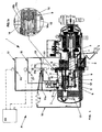
- the compressor of the invention is represented in longitudinal section in Figure 1 , where it is indicated as a whole by 1, and where it can be observed that it is of the volumetric type with screw and comprises a casing 2 in which it is possible to identify a suction chamber 3 and a delivery chamber 4 , between which a pair of screw rotors is included, each rotor being indicated by 5 and only one of them being visible in the drawing.
- pan 6 In the lower part of the casing 2 there is a pan 6 suited to contain the lubrication oil.
- the flow paths 14 comprise a first flow path 14a made in the bottom 15 of the cylinder 10 and a second and a third flow path, 14b and 14c respectively, that instead are both made in the liner of the cylinder 10.
- the flow paths made in the liner are aligned, and in particular the second flow path 14b is in an intermediate position between the bottom 15 and the third flow path 14c.
- the solenoid valves are electrically connected to a control unit 23 provided with means suitable for opening/closing the solenoid valves themselves.
- the adjustment unit 7 comprises also a flow switching unit 30, 40 that connects the active chamber 11 of the actuator 9 to the pan 6 and to the suction chamber 3 and comprises a static flow switch removably associated with a switching solenoid valve 22 electrically connected to the control unit 23, the switching solenoid valve 22 being suited to be associated, alternatively, with static flow switches 31, 41, different from each other, that make it possible to obtain deliveries of compressed fluid varying discretely or continuously, depending on the open or closed position of said solenoid valves 20, 21, 22 and on the consequent position of the slide valve 8 with respect to the rotors 5.
- the flow switching unit 30 comprises the switching solenoid valve 22 associated with the first static flow switch 31, in which it is possible to identify:
- This first executive embodiment makes it possible to obtain compressed fluid delivery values that vary discretely depending on the opening and closing positions of the on-off valves 20 and 21 and of the switching valve 22.
- the first executive embodiment of Figure 1 corresponds to the first flow configuration indicated as a whole by A and corresponding to the ducts marked with a thick line in Figure 1 , in which all the valves are closed and the oil flows from the pan 6 to the active chamber 11 through the delivery duct 16 and the first flow duct 31a of the first static switch 31, thus closing the slide valve 8 completely and obtaining the maximum delivery of the compressor.
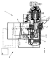
- the compressor of the invention in its first executive embodiment represented in Figure 1 and equipped with the first static switch 31, may also have the second flow configuration indicated as a whole by B, that can be observed in Figure 2 , where the switching valve 22 is opened so that, through the third drain duct 19, the third flow path 14c drains a part of the oil contained in the active chamber 11 into the suction chamber 3, making the piston 12 move backward and the slide valve 8 move in the direction indicated by the arrow V.
- the backward movement of the slide valve 8 opens the clearance L1 that recirculates a part of the sucked air I in the suction chamber 3 of the compressor.
- the degree of reduction in delivery depends on the quantity of oil that is drained from the active chamber 11 and therefore on the position of the third flow path 14c.
- the reduction is such as to achieve a delivery value equal to 75% of the total delivery.
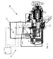
- the same first executive embodiment of the compressor may also have the third flow configuration indicated by C and represented in Figure 3 , where the second on-off valve 21 is opened and it is the second flow path 14b that, through the second drain duct 18, drains oil from the active chamber 11 into the suction chamber 3 of the compressor.
- the active chamber 11 Due to the position of the second flow path 14b, included between the bottom 15 and the third flow path 14c, the active chamber 11 is emptied to a higher extent, in such a way as to achieve, in the executive embodiment described herein, a delivery value equal to 50% of the total value.
- the clearance L3 is larger than in the previous configurations and makes it possible to achieve a delivery of compressed air equal to 25% of the total delivery.
- a second executive embodiment of the compressor of the invention is represented in Figure 5 , where it is indicated as a whole by 50 and where it can be observed that it differs from the executive embodiment described above and represented in the Figures from 1 to 4 due to the fact that the flow switching unit indicated as a whole by 40, comprises the same switching solenoid valve 22 previously described and represented, with which a second static flow switch 41 is associated.
- Said static flow switch 41 comprises:
- Said second executive embodiment of Figure 5 corresponds to the fifth flow configuration indicated as a whole by E , in which the piston 12 is in the most advanced position with the slide valve 8 that completely prevents any recycling of air inside the suction chamber 3.
- the compressor reaches 100% of the total delivery of compressed fluid.
- the second executive embodiment of Figure 5 may have the sixth flow configuration indicated as a whole by F, that can be observed in Figure 6 , in which the second on-off valve 21 is opened in such a way as to place the second flow path 14a of the active chamber 11 of the actuator 9 in communication with the suction chamber 3 of the compressor.
- the slide valve 8 opens the same clearance L2 that can be observed in Figure 3 and the compressor's delivery is equal to 50% of the maximum value.
- Any intermediate delivery value depends on the opening time of the second on-off valve 21 after the active chamber 11 of the cylinder 10 has been completely filled.
- the second executive embodiment of the compressor represented in Figure 5 also makes it possible to obtain the seventh flow configuration, indicated as a whole by G in Figure 7 , in which the opening of the first on-off valve 20 involves the opening of the clearance L3 of the slide valve 8 and therefore the operation of the compressor at 25% of the maximum delivery value.
- first static flow switch 31 and the second static flow switch 41 are represented in Figures 8 and 9 respectively, where it can be observed that they are constituted by metal plates 32, 42, substantially shaped according to a rhomboidal profile and provided with holes 33, 43 for the passage of fastening screws to fix them to the casing of the compressor 2 and to the switching solenoid valve 22.
- a first plate 32 is also provided with the above mentioned first 31a and second 31b flow ducts, while a second plate 42 is provided with the flow duct 41c and with the pair of blind paths 41a, 41b.
- the solenoid valve 22 in both figures, is represented schematically.
- oil conveying ducts may be carried out in any shape and size and may be installed in any position inside the compressor casing, for example according to the configuration shown in Figures 8 and 9 , which is only indicative even if corresponding to a favourite executive embodiment.
Landscapes
- Engineering & Computer Science (AREA)
- Mechanical Engineering (AREA)
- General Engineering & Computer Science (AREA)
- Applications Or Details Of Rotary Compressors (AREA)
- Compressor (AREA)
- Structures Of Non-Positive Displacement Pumps (AREA)
Claims (16)
- Volumetrischer Schraubenkompressor (1; 50), Folgendes umfassend:- ein Gehäuse (2), in dem eine Ansaugkammer (3) und eine Druckkammer (4) erkennbar sind, zwischen denen sich ein Paar Schraubenrotoren (5) befindet;- eine Öl enthaltende Wanne (6);- eine Regeleinheit (7) zur Regulierung der Förderleistung des besagten Kompressors (1), Folgendes umfassend:dadurch gekennzeichnet, dass sich die besagte Durchfluss-Umschalteinheit (30; 40) aus folgenden Teilen zusammensetzt:- ein Schieberventil (8), das extern mit den besagten Rotoren (5) zusammenarbeitet;- einen fluidbetriebenen Aktuator (9), bestehend aus einem Zylinder (10), in dem eine aktive Kammer (11) identifiziert werden kann mit einem Gleitkolben (12), der über eine Stange (13) mit dem besagten Schieberventil (8) verbunden ist;- erste, zweite und dritte Flusswege (14a, 14b, 14c) in dem besagten Zylinder (10), in Entsprechung mit der besagten aktiven Kammer (11), von denen jeder durch entsprechende erste, zweite und dritte Abflussleitungen (17, 18, 19) mit der besagten Ansaugkammer (3) verbunden ist;- wenigstens eine Ölausgabeleitung (16), die mit der besagten Wanne (6) verbunden ist;- ein erstes Ein-/Aus-Magnetventil (20), das in die besagte, erste Abflussleitung (17) eingesetzt ist;- ein zweites Ein-/Aus-Magnetventil (21), das in die besagte, zweite Abflussleitung (18) eingesetzt ist;- wenigstens eine Steuereinheit (23) für die besagten Magnetventile (20, 21);- eine Durchfluss-Umschalteinheit (30; 40), die die besagte aktive Kammer (11) mit der besagten Wanne (6) und mit der besagten Ansaugkammer (3) verbindet,- ein Umschalt-Magnetventil (22), das elektrisch mit der besagten Steuereinheit (23) verbunden ist;- ein erster, statischer Durchflussumschalter (31) und ein zweiter, statischer Durchflussumschalter (41), welche beide alternativ zueinander abnehmbar dem besagtem Umschalt-Magnetventil (22) zugeordnet sind und beide mit Durchflussleitungen (31 a, 31 b; 41 c) versehen sind, die so konfiguriert sind, dass sie zwischen dem besagten Umschaltventil (22), der besagten aktiven Kammer (11), der besagten Wanne (6) und der besagten Ansaugkammer (3) bezüglich des jeweils anderen, statischen Durchflussumschalters (31; 41) unterschiedliche Verbindungen definieren,wobei der besagte erste statische Durchflussumschalter (31) in Verbindung mit dem besagten Umschalt-Magnetventil (22) Folgendes definiert:- eine erste Durchflussleitung (31 a), welche die besagte Ausgabeleitung (16) in einer mittleren Position (17a) zwischen dem besagten ersten Ein-/Aus-Magnetventil (20) und dem besagten Zylinder (10) mit der besagten, ersten Abflussleitung (17) verbindet;- eine zweite Durchflussleitung (31 b), die bezüglich des besagten Umschalt-Magnetventils (22) in Reihe angeordnet und in die besagte dritte Abflussleitung (19) eingefügt ist,um Ausgaben komprimierten Fluids zu erreichen, welche unstetig je nach der offenen oder geschlossenen Position der besagten Magnetventile (20, 21, 22) variieren,
und wobei der besagte zweite, statische Durchflussumschalter (41) in Verbindung mit dem besagten Umschalt-Magnetventil (22) Folgendes definiert:- ein Paar blinder Wege (41 a, 41 b), die die besagte, dritte Abflussleitung (19) absperren;- eine Durchflussleitung (41 c), bezüglich des besagten Umschalt-Magnetventils (22) in Reihe angeordnet, um die besagte Ausgabeleitung (16) in der besagten, mittleren Position (17a) mit der besagten, ersten Abflussleitung (17) zu verbinden,um Ausgaben komprimierten Fluids zu erreichen, welche kontinuierlich je nach der offenen oder geschlossenen Position der besagten Magnetventile (20, 21, 22) variieren. - Kompressor (1) gemäß Patentanspruch 1), dadurch gekennzeichnet, dass der besagte erste, statische Durchflussumschalter (31) dem besagten Umschalt-Magnetventil (22) zugeordnet ist und dass die besagten Magnetventile (20, 21, 22) gemäß einer ersten Konfiguration (A) angeordnet sind, bei welcher:- das besagte erste Ein-/Aus-Magnetventil (20) geschlossen ist;- das besagte zweite Ein-/Aus-Magnetventil (21) geschlossen ist;- das besagte Umschalt-Magnetventil (22) geschlossen ist,wobei die besagte, erste Konfiguration (A) geeignet ist, 100% der Ausgabe komprimierten Fluids zu erreichen.
- Kompressor (1) gemäß Patentanspruch 1), dadurch gekennzeichnet, dass der besagte erste, statische Durchflussumschalter (31) dem besagten Umschalt-Magnetventil (22) zugeordnet ist und dass die besagten Magnetventile (20, 21, 22) gemäß einer zweiten Konfiguration (B) angeordnet sind, bei welcher:- das besagte erste Ein-/Aus-Magnetventil (20) geschlossen ist;- das besagte zweite Ein-/Aus-Magnetventil (21) geschlossen ist;- das besagte Umschalt-Magnetventil (22) geöffnet ist,wobei die besagte, zweite Konfiguration (B) geeignet ist, 75% der Ausgabe komprimierten Fluids zu erreichen.
- Kompressor (1) gemäß Patentanspruch 1), dadurch gekennzeichnet, dass der besagte erste, statische Durchflussumschalter (31) dem besagten Umschalt-Magnetventil (22) zugeordnet ist und dass die besagten Magnetventile (20, 21, 22) gemäß einer dritten Konfiguration (C) angeordnet sind, bei welcher:- das besagte erste Ein-/Aus-Magnetventil (20) geschlossen ist;- das besagte zweite Ein-/Aus-Magnetventil (21) geöffnet ist;- das besagte Umschalt-Magnetventil (22) geschlossen ist,wobei die besagte, dritte Konfiguration (C) geeignet ist, 50% der Ausgabe komprimierten Fluids zu erreichen.
- Kompressor (1) gemäß Patentanspruch 1), dadurch gekennzeichnet, dass der besagte erste, statische Durchflussumschalter (31) dem besagten Umschalt-Magnetventil (22) zugeordnet ist und dass die besagten Magnetventile (20, 21, 22) gemäß einer vierten Konfiguration (D) angeordnet sind, bei welcher:- das besagte erste Ein-/Aus-Magnetventil (20) geöffnet ist;- das besagte zweite Ein-/Aus-Magnetventil (21) geschlossen ist;- das besagte Umschalt-Magnetventil (22) geschlossen ist,wobei die besagte, vierte Konfiguration (D) geeignet ist, 25% der Ausgabe komprimierten Fluids zu erreichen.
- Kompressor (50) gemäß Patentanspruch 1), dadurch gekennzeichnet, dass der besagte zweite, statische Durchflussumschalter (41) dem besagten Umschalt-Magnetventil (22) zugeordnet ist und dass die besagten Magnetventile (20, 21, 22) gemäß einer fünften Konfiguration (E) angeordnet sind, bei welcher:- das besagte erste Ein-/Aus-Magnetventil (20) geschlossen ist;- das besagte zweite Ein-/Aus-Magnetventil (21) geschlossen ist;- das besagte Umschalt-Magnetventil (22) geöffnet ist,wobei die besagte, fünfte Konfiguration (E) geeignet ist, 100% der Ausgabe komprimierten Fluids zu erreichen.
- Kompressor (50) gemäß Patentanspruch 1), dadurch gekennzeichnet, dass der besagte zweite, statische Durchflussumschalter (41) dem besagten Umschalt-Magnetventil (22) zugeordnet ist und dass die besagten Magnetventile (20, 21, 22) gemäß einer sechsten Konfiguration (F) angeordnet sind, bei welcher:- das besagte erste Ein-/Aus-Magnetventil (20) geschlossen ist;- das besagte zweite Ein-/Aus-Magnetventil (21) über einen variablen Zeitraum geöffnet ist und dann wieder geschlossen wird;- das besagte Umschalt-Magnetventil (22) geschlossen ist,wobei die besagte, sechste Konfiguration (F) geeignet ist, einen zwischen 100% und 50% schwankenden Wert der Ausgabe komprimierten Fluids zu erreichen, je nachdem, wie lange die Öffnungszeit des besagten zweiten Magnetventils (21) andauert.
- Kompressor (50) gemäß Patentanspruch 1), dadurch gekennzeichnet, dass der besagte zweite, statische Durchflussumschalter (41) dem besagten Umschalt-Magnetventil (22) zugeordnet ist und dass die besagten Magnetventile (20, 21, 22) gemäß einer siebten Konfiguration (G) angeordnet sind, bei welcher:- das besagte erste Ein-/Aus-Magnetventil (20) geöffnet ist;- das besagte zweite Ein-/Aus-Magnetventil (21) geschlossen ist;- das besagte Umschalt-Magnetventil (22) über einen variablen Zeitraum geöffnet ist und dann wieder geschlossen wird,wobei die besagte, siebte Konfiguration (G) geeignet ist, einen zwischen 100% und 25% schwankenden Wert der Ausgabe komprimierten Fluids zu erreichen, je nachdem, wie lange die Öffnungszeit des besagten Umschalt-Magnetventils (22) andauert.
- Kompressor (1; 50) gemäß Patentanspruch 1), dadurch gekennzeichnet, dass der besagte erste(14a), der besagte zweite (14b) und der besagte dritte (14c) Durchflussweg der besagten aktiven Kammer (11) in unterschiedlichen Abständen zum Boden (15) des besagten Zylinders (10) positioniert sind.
- Kompressor (1; 50) gemäß Patentanspruch 9), dadurch gekennzeichnet, dass der besagte erste Durchflussweg (14a) im Boden (15) des besagten Zylinders (10) ausgeführt ist und dass der besagte zweite (14b) und der besagte dritte (14c) Durchflussweg in der Laufbuchse des besagten Zylinders (10) ausgeführt sind.
- Kompressor (1; 50) gemäß Patentanspruch 10), dadurch gekennzeichnet, dass der besagte zweite Durchflussweg (14b) in einer mittleren Position zwischen dem besagten Boden (15) und dem besagten dritten Durchflussweg (14c) ausgeführt ist.
- Kompressor (1; 50) gemäß Patentanspruch 10), dadurch gekennzeichnet, dass der besagte zweite (14b) und der besagte dritte (14c) Durchflussweg aufeinander ausgerichtet sind.
- Kompressor (1; 50) gemäß Patentanspruch 1), dadurch gekennzeichnet, dass die besagte Steuereinheit (23) elektrisch mit jedem der besagten Magnetventile (20, 21, 22) verbunden ist und elektrische/elektronische Mittel zum Öffnen/Schließen der besagten Magnetventile umfasst.
- Kompressor (1; 50) gemäß Patentanspruch 1), dadurch gekennzeichnet, dass jeder der besagten, statischen Durchflussumschalter (31; 41) aus geformten Metallplatten (32; 42) besteht, wobei jede dieser Platten mit Bohrungen (33; 43) für den Durchgang von Befestigungsschrauben versehen ist, um sie an dem besagten Umschalt-Magnetventil (22) und an dem besagten Gehäuse (2) zu befestigen.
- Kompressor (1) gemäß Patentanspruch 14), dadurch gekennzeichnet, dass die besagten, geformten Metallplatten eine erste Platte (32) umfassen, welche eine erste (31 a) und eine zweite (31 b) Durchflussleitung aufweist.
- Kompressor (50) gemäß Patentanspruch 14), dadurch gekennzeichnet, dass die besagten, geformten Metallplatten eine zweite Platte (42) umfassen, welche eine Durchflussleitung (41 c) sowie ein Paar blinder Wege (41 a, 41 b) aufweist.
Applications Claiming Priority (2)
| Application Number | Priority Date | Filing Date | Title |
|---|---|---|---|
| IT000034A ITVI20040034A1 (it) | 2004-03-03 | 2004-03-03 | Compressore volumetrico a vite con dispositivo di regolazione della portata |
| PCT/EP2005/050933 WO2005085644A1 (en) | 2004-03-03 | 2005-03-02 | Volumetric screw compressor provided with delivery adjustment device. |
Publications (2)
| Publication Number | Publication Date |
|---|---|
| EP1730406A1 EP1730406A1 (de) | 2006-12-13 |
| EP1730406B1 true EP1730406B1 (de) | 2011-11-23 |
Family
ID=34917562
Family Applications (1)
| Application Number | Title | Priority Date | Filing Date |
|---|---|---|---|
| EP05716891A Expired - Lifetime EP1730406B1 (de) | 2004-03-03 | 2005-03-02 | Mit abgabeeinstellvorrichtung versehener volumetrischer schraubenverdichter |
Country Status (6)
| Country | Link |
|---|---|
| US (1) | US7481634B2 (de) |
| EP (1) | EP1730406B1 (de) |
| CN (1) | CN100582486C (de) |
| AT (1) | ATE534823T1 (de) |
| IT (1) | ITVI20040034A1 (de) |
| WO (1) | WO2005085644A1 (de) |
Families Citing this family (7)
| Publication number | Priority date | Publication date | Assignee | Title |
|---|---|---|---|---|
| ITVI20050272A1 (it) | 2005-10-14 | 2007-04-15 | Refcomp Spa | Compressore volumetrico a vite perfezionato |
| US10941770B2 (en) | 2010-07-20 | 2021-03-09 | Trane International Inc. | Variable capacity screw compressor and method |
| CN106593874B (zh) * | 2016-12-28 | 2019-01-04 | 珠海格力电器股份有限公司 | 与阀配合的过渡安装构件及具有该构件的压缩机 |
| US10876531B2 (en) | 2018-12-26 | 2020-12-29 | Trane International Inc. | Lubricant injection for a screw compressor |
| CN113550902B (zh) * | 2020-04-24 | 2023-03-31 | 青岛海尔空调电子有限公司 | 螺杆压缩机的卸载控制方法 |
| CN111794969A (zh) * | 2020-04-24 | 2020-10-20 | 青岛海尔空调电子有限公司 | 螺杆压缩机的卸载控制方法 |
| CN117536864A (zh) * | 2023-10-24 | 2024-02-09 | 武汉纺织大学 | 一种即时供油的螺杆式制冷压缩机装置 |
Family Cites Families (10)
| Publication number | Priority date | Publication date | Assignee | Title |
|---|---|---|---|---|
| JPS59211784A (ja) * | 1983-05-18 | 1984-11-30 | Hitachi Ltd | 連続制御付スクリユ−形空調機 |
| JPS60164693A (ja) * | 1984-02-06 | 1985-08-27 | Daikin Ind Ltd | スクリユ−圧縮機の容量制御装置 |
| JPS60216092A (ja) * | 1984-04-11 | 1985-10-29 | Hitachi Ltd | スクリユ−圧縮機の起動負荷軽減装置 |
| JPS63106391A (ja) * | 1986-10-24 | 1988-05-11 | Hitachi Ltd | 油冷式スクリユ−冷凍機の給油装置 |
| JPH06173872A (ja) * | 1992-12-03 | 1994-06-21 | Hitachi Ltd | スクリュー圧縮機 |
| JPH07259778A (ja) * | 1994-03-18 | 1995-10-09 | Daikin Ind Ltd | スクリュー圧縮機の容量制御装置 |
| JP3796836B2 (ja) * | 1996-09-20 | 2006-07-12 | 株式会社日立製作所 | スクリュー圧縮機 |
| JPH1113675A (ja) * | 1997-06-20 | 1999-01-19 | Hitachi Ltd | スクリュー圧縮機の容量制御装置 |
| JP3996678B2 (ja) * | 1997-09-11 | 2007-10-24 | 日立アプライアンス株式会社 | スクリュー圧縮機の容量制御装置 |
| DE19935041A1 (de) * | 1999-07-26 | 2001-02-08 | Bitzer Kuehlmaschinenbau Gmbh | Schraubenverdichter |
-
2004
- 2004-03-03 IT IT000034A patent/ITVI20040034A1/it unknown
-
2005
- 2005-03-02 CN CN200580006835A patent/CN100582486C/zh not_active Expired - Fee Related
- 2005-03-02 WO PCT/EP2005/050933 patent/WO2005085644A1/en not_active Ceased
- 2005-03-02 US US10/591,562 patent/US7481634B2/en not_active Expired - Fee Related
- 2005-03-02 AT AT05716891T patent/ATE534823T1/de active
- 2005-03-02 EP EP05716891A patent/EP1730406B1/de not_active Expired - Lifetime
Also Published As
| Publication number | Publication date |
|---|---|
| ITVI20040034A1 (it) | 2004-06-03 |
| US20070274852A1 (en) | 2007-11-29 |
| US7481634B2 (en) | 2009-01-27 |
| CN100582486C (zh) | 2010-01-20 |
| WO2005085644A1 (en) | 2005-09-15 |
| ATE534823T1 (de) | 2011-12-15 |
| EP1730406A1 (de) | 2006-12-13 |
| CN101014771A (zh) | 2007-08-08 |
Similar Documents
| Publication | Publication Date | Title |
|---|---|---|
| DE69928055T2 (de) | Liefermengenregelung eines Verdichters | |
| EP1730406B1 (de) | Mit abgabeeinstellvorrichtung versehener volumetrischer schraubenverdichter | |
| EP1612420B1 (de) | Regelventil für einen Kompressor mit veränderlicher Verdrängung | |
| CN101600884B (zh) | 螺旋式压缩机容量控制 | |
| CN102678223B (zh) | 用于内燃机的供油装置 | |
| CA2611208C (en) | A pneumatic drive system | |
| EP3133288B1 (de) | Schraubenverdichter | |
| CN102734158A (zh) | 螺旋式压缩机及使用该螺旋式压缩机的冷风装置 | |
| CN100523671C (zh) | 制冷剂压缩机 | |
| US8690545B2 (en) | Reciprocating piston compressor | |
| US6467287B2 (en) | Valve arrangement for a compressor | |
| EP2196676B1 (de) | Temperaturregelung durch Impulsbreitenmodulation | |
| CN107621100B (zh) | 可变经济器注射位置 | |
| JP5530825B2 (ja) | スクリュー圧縮機およびその制御装置 | |
| EP1775474B1 (de) | Schraubenverdichter | |
| DE102005061817A1 (de) | Verdrängungssteuermechanismus für einen Kompressor mit variabler Verdrängung | |
| WO2011048618A1 (en) | Screw compressor with variable compression ratio | |
| EP2417357A1 (de) | Insbesondere zur parallelverbindung in kompressionseinheiten geeigneter schraubenkompressor | |
| KR101211782B1 (ko) | 대형디젤엔진에 실린더면의 윤활방법과 윤활장치 | |
| JPH08151987A (ja) | スクリュー圧縮機の容量制御装置 | |
| KR20190091835A (ko) | 전자식 제어 밸브 및 그를 포함한 압축기 | |
| KR102818391B1 (ko) | 압축기의 리어하우징 | |
| CN116971987A (zh) | 背压调节方法、背压控制系统、涡旋压缩机及制冷系统 | |
| KR100993771B1 (ko) | 용량가변형 압축기의 밸브 어셈블리 | |
| KR101336557B1 (ko) | 가변용량형 사판식 압축기 |
Legal Events
| Date | Code | Title | Description |
|---|---|---|---|
| PUAI | Public reference made under article 153(3) epc to a published international application that has entered the european phase |
Free format text: ORIGINAL CODE: 0009012 |
|
| 17P | Request for examination filed |
Effective date: 20061004 |
|
| AK | Designated contracting states |
Kind code of ref document: A1 Designated state(s): AT BE BG CH CY CZ DE DK EE ES FI FR GB GR HU IE IS IT LI LT LU MC NL PL PT RO SE SI SK TR |
|
| DAX | Request for extension of the european patent (deleted) | ||
| 17Q | First examination report despatched |
Effective date: 20090414 |
|
| GRAP | Despatch of communication of intention to grant a patent |
Free format text: ORIGINAL CODE: EPIDOSNIGR1 |
|
| GRAS | Grant fee paid |
Free format text: ORIGINAL CODE: EPIDOSNIGR3 |
|
| GRAA | (expected) grant |
Free format text: ORIGINAL CODE: 0009210 |
|
| AK | Designated contracting states |
Kind code of ref document: B1 Designated state(s): AT BE BG CH CY CZ DE DK EE ES FI FR GB GR HU IE IS IT LI LT LU MC NL PL PT RO SE SI SK TR |
|
| REG | Reference to a national code |
Ref country code: GB Ref legal event code: FG4D |
|
| REG | Reference to a national code |
Ref country code: CH Ref legal event code: EP |
|
| REG | Reference to a national code |
Ref country code: IE Ref legal event code: FG4D |
|
| REG | Reference to a national code |
Ref country code: DE Ref legal event code: R096 Ref document number: 602005031338 Country of ref document: DE Effective date: 20120119 |
|
| REG | Reference to a national code |
Ref country code: NL Ref legal event code: VDEP Effective date: 20111123 |
|
| LTIE | Lt: invalidation of european patent or patent extension |
Effective date: 20111123 |
|
| PG25 | Lapsed in a contracting state [announced via postgrant information from national office to epo] |
Ref country code: LT Free format text: LAPSE BECAUSE OF FAILURE TO SUBMIT A TRANSLATION OF THE DESCRIPTION OR TO PAY THE FEE WITHIN THE PRESCRIBED TIME-LIMIT Effective date: 20111123 Ref country code: IS Free format text: LAPSE BECAUSE OF FAILURE TO SUBMIT A TRANSLATION OF THE DESCRIPTION OR TO PAY THE FEE WITHIN THE PRESCRIBED TIME-LIMIT Effective date: 20120323 |
|
| PG25 | Lapsed in a contracting state [announced via postgrant information from national office to epo] |
Ref country code: SE Free format text: LAPSE BECAUSE OF FAILURE TO SUBMIT A TRANSLATION OF THE DESCRIPTION OR TO PAY THE FEE WITHIN THE PRESCRIBED TIME-LIMIT Effective date: 20111123 Ref country code: BE Free format text: LAPSE BECAUSE OF FAILURE TO SUBMIT A TRANSLATION OF THE DESCRIPTION OR TO PAY THE FEE WITHIN THE PRESCRIBED TIME-LIMIT Effective date: 20111123 Ref country code: NL Free format text: LAPSE BECAUSE OF FAILURE TO SUBMIT A TRANSLATION OF THE DESCRIPTION OR TO PAY THE FEE WITHIN THE PRESCRIBED TIME-LIMIT Effective date: 20111123 Ref country code: SI Free format text: LAPSE BECAUSE OF FAILURE TO SUBMIT A TRANSLATION OF THE DESCRIPTION OR TO PAY THE FEE WITHIN THE PRESCRIBED TIME-LIMIT Effective date: 20111123 Ref country code: PT Free format text: LAPSE BECAUSE OF FAILURE TO SUBMIT A TRANSLATION OF THE DESCRIPTION OR TO PAY THE FEE WITHIN THE PRESCRIBED TIME-LIMIT Effective date: 20120323 Ref country code: GR Free format text: LAPSE BECAUSE OF FAILURE TO SUBMIT A TRANSLATION OF THE DESCRIPTION OR TO PAY THE FEE WITHIN THE PRESCRIBED TIME-LIMIT Effective date: 20120224 |
|
| PG25 | Lapsed in a contracting state [announced via postgrant information from national office to epo] |
Ref country code: CY Free format text: LAPSE BECAUSE OF FAILURE TO SUBMIT A TRANSLATION OF THE DESCRIPTION OR TO PAY THE FEE WITHIN THE PRESCRIBED TIME-LIMIT Effective date: 20111123 |
|
| PG25 | Lapsed in a contracting state [announced via postgrant information from national office to epo] |
Ref country code: DK Free format text: LAPSE BECAUSE OF FAILURE TO SUBMIT A TRANSLATION OF THE DESCRIPTION OR TO PAY THE FEE WITHIN THE PRESCRIBED TIME-LIMIT Effective date: 20111123 Ref country code: CZ Free format text: LAPSE BECAUSE OF FAILURE TO SUBMIT A TRANSLATION OF THE DESCRIPTION OR TO PAY THE FEE WITHIN THE PRESCRIBED TIME-LIMIT Effective date: 20111123 Ref country code: SK Free format text: LAPSE BECAUSE OF FAILURE TO SUBMIT A TRANSLATION OF THE DESCRIPTION OR TO PAY THE FEE WITHIN THE PRESCRIBED TIME-LIMIT Effective date: 20111123 Ref country code: BG Free format text: LAPSE BECAUSE OF FAILURE TO SUBMIT A TRANSLATION OF THE DESCRIPTION OR TO PAY THE FEE WITHIN THE PRESCRIBED TIME-LIMIT Effective date: 20120223 Ref country code: EE Free format text: LAPSE BECAUSE OF FAILURE TO SUBMIT A TRANSLATION OF THE DESCRIPTION OR TO PAY THE FEE WITHIN THE PRESCRIBED TIME-LIMIT Effective date: 20111123 |
|
| PGFP | Annual fee paid to national office [announced via postgrant information from national office to epo] |
Ref country code: DE Payment date: 20120427 Year of fee payment: 8 |
|
| PG25 | Lapsed in a contracting state [announced via postgrant information from national office to epo] |
Ref country code: PL Free format text: LAPSE BECAUSE OF FAILURE TO SUBMIT A TRANSLATION OF THE DESCRIPTION OR TO PAY THE FEE WITHIN THE PRESCRIBED TIME-LIMIT Effective date: 20111123 Ref country code: RO Free format text: LAPSE BECAUSE OF FAILURE TO SUBMIT A TRANSLATION OF THE DESCRIPTION OR TO PAY THE FEE WITHIN THE PRESCRIBED TIME-LIMIT Effective date: 20111123 |
|
| REG | Reference to a national code |
Ref country code: AT Ref legal event code: MK05 Ref document number: 534823 Country of ref document: AT Kind code of ref document: T Effective date: 20111123 |
|
| PLBE | No opposition filed within time limit |
Free format text: ORIGINAL CODE: 0009261 |
|
| STAA | Information on the status of an ep patent application or granted ep patent |
Free format text: STATUS: NO OPPOSITION FILED WITHIN TIME LIMIT |
|
| 26N | No opposition filed |
Effective date: 20120824 |
|
| PG25 | Lapsed in a contracting state [announced via postgrant information from national office to epo] |
Ref country code: MC Free format text: LAPSE BECAUSE OF NON-PAYMENT OF DUE FEES Effective date: 20120331 |
|
| REG | Reference to a national code |
Ref country code: CH Ref legal event code: PL |
|
| GBPC | Gb: european patent ceased through non-payment of renewal fee |
Effective date: 20120302 |
|
| REG | Reference to a national code |
Ref country code: FR Ref legal event code: ST Effective date: 20121130 |
|
| REG | Reference to a national code |
Ref country code: DE Ref legal event code: R097 Ref document number: 602005031338 Country of ref document: DE Effective date: 20120824 |
|
| REG | Reference to a national code |
Ref country code: IE Ref legal event code: MM4A |
|
| PG25 | Lapsed in a contracting state [announced via postgrant information from national office to epo] |
Ref country code: GB Free format text: LAPSE BECAUSE OF NON-PAYMENT OF DUE FEES Effective date: 20120302 Ref country code: IE Free format text: LAPSE BECAUSE OF NON-PAYMENT OF DUE FEES Effective date: 20120302 Ref country code: CH Free format text: LAPSE BECAUSE OF NON-PAYMENT OF DUE FEES Effective date: 20120331 Ref country code: FR Free format text: LAPSE BECAUSE OF NON-PAYMENT OF DUE FEES Effective date: 20120402 Ref country code: LI Free format text: LAPSE BECAUSE OF NON-PAYMENT OF DUE FEES Effective date: 20120331 Ref country code: AT Free format text: LAPSE BECAUSE OF FAILURE TO SUBMIT A TRANSLATION OF THE DESCRIPTION OR TO PAY THE FEE WITHIN THE PRESCRIBED TIME-LIMIT Effective date: 20111123 |
|
| PG25 | Lapsed in a contracting state [announced via postgrant information from national office to epo] |
Ref country code: ES Free format text: LAPSE BECAUSE OF FAILURE TO SUBMIT A TRANSLATION OF THE DESCRIPTION OR TO PAY THE FEE WITHIN THE PRESCRIBED TIME-LIMIT Effective date: 20120305 |
|
| PG25 | Lapsed in a contracting state [announced via postgrant information from national office to epo] |
Ref country code: FI Free format text: LAPSE BECAUSE OF FAILURE TO SUBMIT A TRANSLATION OF THE DESCRIPTION OR TO PAY THE FEE WITHIN THE PRESCRIBED TIME-LIMIT Effective date: 20111123 |
|
| REG | Reference to a national code |
Ref country code: DE Ref legal event code: R119 Ref document number: 602005031338 Country of ref document: DE Effective date: 20131001 |
|
| PG25 | Lapsed in a contracting state [announced via postgrant information from national office to epo] |
Ref country code: DE Free format text: LAPSE BECAUSE OF NON-PAYMENT OF DUE FEES Effective date: 20131001 |
|
| PGFP | Annual fee paid to national office [announced via postgrant information from national office to epo] |
Ref country code: IT Payment date: 20131017 Year of fee payment: 9 |
|
| PG25 | Lapsed in a contracting state [announced via postgrant information from national office to epo] |
Ref country code: TR Free format text: LAPSE BECAUSE OF FAILURE TO SUBMIT A TRANSLATION OF THE DESCRIPTION OR TO PAY THE FEE WITHIN THE PRESCRIBED TIME-LIMIT Effective date: 20111123 |
|
| PG25 | Lapsed in a contracting state [announced via postgrant information from national office to epo] |
Ref country code: LU Free format text: LAPSE BECAUSE OF NON-PAYMENT OF DUE FEES Effective date: 20120302 |
|
| PG25 | Lapsed in a contracting state [announced via postgrant information from national office to epo] |
Ref country code: HU Free format text: LAPSE BECAUSE OF FAILURE TO SUBMIT A TRANSLATION OF THE DESCRIPTION OR TO PAY THE FEE WITHIN THE PRESCRIBED TIME-LIMIT Effective date: 20050302 |
|
| PG25 | Lapsed in a contracting state [announced via postgrant information from national office to epo] |
Ref country code: IT Free format text: LAPSE BECAUSE OF NON-PAYMENT OF DUE FEES Effective date: 20140302 |