EP1731636A2 - Support pour rouleaux jumelés de pression d'un banc d'étirage - Google Patents
Support pour rouleaux jumelés de pression d'un banc d'étirage Download PDFInfo
- Publication number
- EP1731636A2 EP1731636A2 EP06006651A EP06006651A EP1731636A2 EP 1731636 A2 EP1731636 A2 EP 1731636A2 EP 06006651 A EP06006651 A EP 06006651A EP 06006651 A EP06006651 A EP 06006651A EP 1731636 A2 EP1731636 A2 EP 1731636A2
- Authority
- EP
- European Patent Office
- Prior art keywords
- twin
- pressure roller
- axis
- rollers
- roller
- Prior art date
- Legal status (The legal status is an assumption and is not a legal conclusion. Google has not performed a legal analysis and makes no representation as to the accuracy of the status listed.)
- Withdrawn
Links
Images

Classifications
-
- D—TEXTILES; PAPER
- D01—NATURAL OR MAN-MADE THREADS OR FIBRES; SPINNING
- D01H—SPINNING OR TWISTING
- D01H5/00—Drafting machines or arrangements ; Threading of roving into drafting machine
- D01H5/18—Drafting machines or arrangements without fallers or like pinned bars
- D01H5/56—Supports for drafting elements
- D01H5/565—Top roller arms
Definitions
- the invention relates to a holder for a fixed axis and two rotatably mounted upper rollers having Druckwalzenzwilling a multiple lower rollers having drafting with at least one axis of Druckwalzenzwillings associated positioning element and at least one force application element, wherein the positioning element is arranged in the region of the center of the axis of Druckwalzenzwillings and the pressure roller twin allows oscillation about the center, and wherein the holder with the pressure roller twin of the lower rollers is lifted.
- the printing roll twin is held in the center of its axis by a positioning element and positioned with respect to the associated lower roller.
- the positioning element is adjustable in the fiber transport direction and allows the setting of a so-called curtain or rear of the top rollers.
- the axes of rotation of the upper rollers with respect to the fiber transport direction are arranged offset slightly to the rotational axes of the lower roller forward or backward.
- the axis of Druckwalzenzwillings is included in the positioning element, that a commuting around the center is made possible.
- the introduction of force of a pressing force for the load of the top rollers is integrated in the positioning element in the middle of the axis of the pressure roller twin.
- the known holder has proven very well in practice at drafting systems with relatively small pitch, for example in drafting systems for ring spinning machines. After lifting the Druckwalzenzwillings from the lower rollers, which may be necessary, for example, for troubleshooting, find the top rollers when placed on the lower rollers automatically back to their position of the set front or rear, and the pressure roller twin is directed by the pendulum back to exactly the lower roller.
- the holder with the positioning element need not be aligned parallel to the lower rollers. This is a decisive advantage, since usually a large number of components is used for fastening and loading of the holder with the pressing force, in which a good parallelism of Positions mecanices with the lower rollers can not be guaranteed by the addition of individual tolerances.
- the invention is based on the object to improve the known holder and to allow even in drafting systems with large pitches a pendulum option of Druckwalzenzwillings without incorrect positioning of the upper rollers is possible when placing the Druckwalzenzwillings.
- the object is achieved in that at least one backup bearing for coarse positioning when placed on the lower rollers is assigned to the printing roll at least.
- the pendulum option of Druckwalzenzwillings can be adjusted so that when placing the Druckwalzenzwillings a mispositioning of the two upper rollers is excluded and that nevertheless can take place during application of the pressing force parallel alignment of Druckwalzenzwillings to the lower rollers.
- the fishing camps act at least shortly before the placement of the pressure roller twin and advantageously provide a rough parallel alignment of the pressure roller twin to an extent that the top rollers of the pressure roller twin, depending on the selected setting either sit with curtain or both with the back of the lower rollers.
- the provided within the coarse parallel alignment pendulum option then allows the pressure roll twin then when applying the pressing force to be able to align exactly parallel to the lower rollers. An attachment of a top roller with curtain and the other top roller with the back is effectively prevented.
- the fishing camp can be designed in different ways.
- it acts as far as possible from the center of the axis on the twin pressure roll.
- the backup bearing should limit the pendulum movement of the pressure roller twin so far that a false placement of the top rollers is prevented, on the other hand, however, a sufficiently large pendulum must remain that under the action of the pressing force exact parallel alignment of Druckwalzenzwillings is possible.
- the safety bearing is thus designed so that it leads to the pressure roller twin until it touches the lower rollers, then but does not hinder the twin-roll twin in its pendulum alignment parallel to the lower rolls.
- the backup bearing can be assigned to a top roller of the pressure roller twin, but it has a particularly advantageous effect on the axis of the pressure roller twin, since it does not start to rotate even when placed on it.
- an advantageous embodiment of the invention is provided when two fishing camps are spaced apart and arranged in the vicinity of the top rollers. It is characterized in a simple manner a symmetrical configuration of the components, in particular the holder, possible. It is also advantageous that the force introduction element, which initiates the pressing force for the top rollers in the axis of the pressure roller twin, is integrated in the positioning element. Thus, the force is introduced together with the positioning in the middle of the axis of the pressure roller twin and the force is divided by itself evenly on both top rollers.
- the safety bearing is advantageously designed like a fork and prevents even when lifting the Druckwalzenzwillings from the lower roller that the pressure roller twin comes too much out of position.
- the drafting system 1 partially shown in Figure 1 includes a plurality of roller pairs 2, 3 and 4, 5, which transport a fiber strand 6 in the fiber transport direction A through the drafting system 1 and thereby forgiven to the desired fineness.
- the roller pair 4, 5 are assigned in a conventional manner guide straps 7 and 8. It can be provided that the drafting arrangement 1 contains further roller pairs, not shown, which precede the roller pair 4, 5 or follow the roller pair 2, 3.
- the distorted to its desired fineness fiber structure 6 is subsequently fed to the drafting a per se arbitrary twist distribution member, such as an air jet unit, where the fiber strand 6 of the spinning twist is issued.
- the upper rollers 3 and 5 are positioned and pressed by brackets 9 with respect to the drivable lower rollers 2 and 4.
- the top rollers 3 and 5 are not driven themselves, but are entrained by the movement of the lower rollers 2, 4.
- the holder 9 is acted upon in any known and known manner by load means, not shown, with a pressing force F and can be lifted with the upper roller 3 or 5 of the lower roller 2 and 4 respectively.
- the pressing force F can be applied both by pneumatic or magnetic force generating elements and by metallic springs.
- the upper rollers 3 of two adjacent spinning stations are combined with a common axle 10 to form a twin-roller 11.
- the two lower rollers 2 of these adjacent spinning stations can be designed as a single bottom rollers with separate drives. But you can as well as in Machine longitudinal direction continuous sub-cylinder be configured in the manner shown in dashed lines.
- the top rollers 3, 5 are arranged with respect to the respective bottom roller 2, 4 with a light curtain or rear.
- the arrangement of the upper roller 5 is referred to the lower roller 4, in which the upper roller 5 seen in the fiber transport direction A slightly further upstream than the lower roller 4 is arranged.
- the roller pair 2, 3 shows a curtain of the upper roller 3, in which the upper roller is arranged in the fiber transport direction A downstream of the lower roller 2.
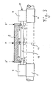
- Figure 2 shows a plan view of the pair of rollers 2, 3, wherein the holder 9 is cut along the sectional surface II-II of Figure 1.
- a positioning element 13 contained in the holder 9 is provided in the area of the center 12 of the axis 10 of the pressure roller twin 11.
- the positioning element 13 has positioning surfaces 14 which cooperate with the axis 10 and ensure the positioning of the pressure roller twin 11 with the desired curtain with respect to the lower rollers 2.
- the positioning surfaces 14 in this case have a clearance fit with the axis 10, so that the pressure roller twin 11 can perform in the direction of arrow B and C about the center 12 a pendulum motion.
- the pendulum option in the direction of arrow B and C in conjunction with the set front or rear causes an automatic alignment of Druckwalzenzwillings parallel to the lower rollers 2.
- a caused by an inclination of the upper roller 3 to the lower roller 2 uneven clamping of the fiber structure 6 with resulting uneven Delay is prevented.
- the positioning surface 14 can also be performed slightly spherical.
- the pendulum motion of the pressure roller twin 11 is so large that it is at a touchdown of the pressure roller twin 11, after this was lifted to eliminate a malfunction of the lower rollers 2 to an incorrect positioning of the pressure roller twin 11 comes.
- the axis 10 of the pressure roller twin is tilted so far that the one top roller 3 touches a curtain and the other top roller 3 with a rear surface on the respective bottom roller 2. In such a state, spinning is not possible.
- the pressure roller twin 11 to allocate at least one fishing camp 15, which when placing the Druckwalzenzwillings 11 on the lower rollers 2 for coarse positioning of the pressure roller twin 11 is used and prevents erroneous placement.
- the fishing camp 15 can be assigned to the axis 10 of the pressure rolling twin 11.
- the fishing camp 15 has at least one catching surface 16, which restricts the pressure roller twin 11 in its pendulum motion in the direction B or C, as soon as the pendulum angle exceeds a certain size.
- the fishing camp 15 is advantageously arranged as far as possible from the center 12 of the pressure rolling twin 11.
- the catching surfaces 16 are arranged at such a distance from the axis 10 of the pressure roller twin that they prevent erroneous placement of Druckwalzenzwillings on the lower rollers, but do not hinder the pendulum motion for parallel alignment of Druckwalzenzwillings. This objective is the more easily achievable, the farther the fishing camp 15 are away from the center 12.
- the pressing force F must be introduced through the holder 9 into the axis 10 of the pressure roller twin. This can be done by integrating a force introduction element into the positioning element 13. In this embodiment, not shown, the pressing force F is distributed by the axis 10 on the two top rollers 3 of the pressure roller twin 11. In the drafting system shown here with a large pitch E and compared to relatively small diameter D of the axis 10 of the pressure rolling twin 11, depending on the size of the pressing force F, the deflection of the axis 10 can become so large that a misalignment of the top rollers 3 occurs due to the deformation , which in turn affects the uniformity of the distorted fiber structure.
- the diameter D of the axis 10 is often less than one-tenth of the pitch E.
- force introduction elements 17, as shown in FIG. 3, separately from the positioning element 13.
- the force introduction element is arranged as close as possible to the top roller 3 and transmits the pressing force F from the holder 9 by pressure surfaces 18 on the axis 10.
- the pressure surfaces 18 are advantageously formed as flat surfaces, which transmit the pressing force F on the axis 10, without affecting the position of the axis 10 and without forcing the pressure roller twin in a possibly wrong position.
- the fishing camp 15 is integrated in the force introduction element 17.
- the integrated component can advantageously be designed like a fork, in which the fork base the pressure surfaces 18 and the side surfaces of the fork contain the catching surfaces 16.
- the upper roller 5 with the ceremoniessriemchen 8 can of course just like the previously described upper roller 3 may be formed as Druckwalzenzwilling 11, which is positioned in the same way by a holder 9 and loaded with a pressing force F.
Landscapes
- Engineering & Computer Science (AREA)
- Mechanical Engineering (AREA)
- Textile Engineering (AREA)
- Spinning Or Twisting Of Yarns (AREA)
- Inking, Control Or Cleaning Of Printing Machines (AREA)
Applications Claiming Priority (1)
| Application Number | Priority Date | Filing Date | Title |
|---|---|---|---|
| DE102005027194A DE102005027194A1 (de) | 2005-06-06 | 2005-06-06 | Halterung für einen Druckwalzenzwillig eines Streckwerkes |
Publications (2)
| Publication Number | Publication Date |
|---|---|
| EP1731636A2 true EP1731636A2 (fr) | 2006-12-13 |
| EP1731636A3 EP1731636A3 (fr) | 2009-04-01 |
Family
ID=36992528
Family Applications (1)
| Application Number | Title | Priority Date | Filing Date |
|---|---|---|---|
| EP06006651A Withdrawn EP1731636A3 (fr) | 2005-06-06 | 2006-03-30 | Support pour rouleaux jumelés de pression d'un banc d'étirage |
Country Status (5)
| Country | Link |
|---|---|
| US (1) | US20060272131A1 (fr) |
| EP (1) | EP1731636A3 (fr) |
| JP (1) | JP2006342480A (fr) |
| CN (1) | CN1876913A (fr) |
| DE (1) | DE102005027194A1 (fr) |
Cited By (1)
| Publication number | Priority date | Publication date | Assignee | Title |
|---|---|---|---|---|
| EP3020854A1 (fr) * | 2014-11-13 | 2016-05-18 | Murata Machinery, Ltd. | Dispositif de tirage et métier à filer |
Families Citing this family (3)
| Publication number | Priority date | Publication date | Assignee | Title |
|---|---|---|---|---|
| CN104368799A (zh) * | 2014-11-14 | 2015-02-25 | 无锡阳工机械制造有限公司 | 压辊支架的加工方法 |
| CN104368795A (zh) * | 2014-11-14 | 2015-02-25 | 柳州兴杜工业贸易有限公司 | 一种工业用辊式结构件的制造工艺 |
| CN108179508A (zh) * | 2018-03-15 | 2018-06-19 | 湖南宏力德成纺织有限公司 | 一种方便牵伸罗拉拆卸安装的环锭纺纱机用罗拉支撑座 |
Family Cites Families (8)
| Publication number | Priority date | Publication date | Assignee | Title |
|---|---|---|---|---|
| FR956609A (fr) * | 1950-02-02 | |||
| US2881481A (en) * | 1955-11-18 | 1959-04-14 | Whitin Machine Works | Top roll positioning and tensioning mechanism for textile drafting apparatus |
| US2890495A (en) * | 1957-07-25 | 1959-06-16 | Alsacienne Constr Meca | Textile drafting apparatus |
| DE1560284A1 (de) * | 1966-08-20 | 1970-10-15 | Schurr Stahlecker & Grill | Oberwalzen-Tragarm fuer Streckwerke von Spinnereimaschinen mit mittengefuehrten Druckwalzen |
| US4187588A (en) * | 1975-12-26 | 1980-02-12 | Ntn Toyo Bearing Co. Ltd. | Construction of pendulum arm type high sensitivity self-aligning weighting arm |
| US4127066A (en) * | 1977-05-11 | 1978-11-28 | Melvin Sharkey | Adjustable compression roller apparatus |
| US4557022A (en) * | 1983-05-20 | 1985-12-10 | Kabushiki Kaisha Toyoda Jidoshokki Seisakusho | Drafting means for textile machine such as spinning machine |
| DE19548840B4 (de) * | 1995-12-27 | 2008-04-03 | Rieter Ingolstadt Spinnereimaschinenbau Ag | Strecke zum Doublieren und Verstrecken von Faserbändern |
-
2005
- 2005-06-06 DE DE102005027194A patent/DE102005027194A1/de not_active Withdrawn
-
2006
- 2006-03-30 EP EP06006651A patent/EP1731636A3/fr not_active Withdrawn
- 2006-04-28 JP JP2006125058A patent/JP2006342480A/ja active Pending
- 2006-06-05 US US11/446,154 patent/US20060272131A1/en not_active Abandoned
- 2006-06-06 CN CNA2006100887947A patent/CN1876913A/zh active Pending
Cited By (3)
| Publication number | Priority date | Publication date | Assignee | Title |
|---|---|---|---|---|
| EP3020854A1 (fr) * | 2014-11-13 | 2016-05-18 | Murata Machinery, Ltd. | Dispositif de tirage et métier à filer |
| CN105603590A (zh) * | 2014-11-13 | 2016-05-25 | 村田机械株式会社 | 牵伸装置以及纺织单元 |
| CN105603590B (zh) * | 2014-11-13 | 2019-09-20 | 村田机械株式会社 | 牵伸装置以及纺织单元 |
Also Published As
| Publication number | Publication date |
|---|---|
| CN1876913A (zh) | 2006-12-13 |
| US20060272131A1 (en) | 2006-12-07 |
| JP2006342480A (ja) | 2006-12-21 |
| EP1731636A3 (fr) | 2009-04-01 |
| DE102005027194A1 (de) | 2006-12-07 |
Similar Documents
| Publication | Publication Date | Title |
|---|---|---|
| DE102007024234B4 (de) | Streckwerk zum Verziehen eines Faserverbandes | |
| DE20210613U1 (de) | Vorrichtung zum Nadeln eines Vlieses | |
| EP1870500B1 (fr) | Banc d'étirage d'une machine de prétraitement de filature | |
| EP1731636A2 (fr) | Support pour rouleaux jumelés de pression d'un banc d'étirage | |
| EP2886689B1 (fr) | Métier à filer et support de table | |
| EP3670718B1 (fr) | Métier à filer à anneaux pourvu de bancs d'étirage | |
| EP4130361B1 (fr) | Banc d'étirage et procédé de chargement et d'ouverture du banc d'étirage | |
| DE2939693C2 (de) | Vliesabnahmevorrichtung | |
| DE3113753C2 (de) | Dreiwalzenbiegemaschine für Blech | |
| DE3872089T2 (de) | Einheit zum aufhaengen einer ringbank. | |
| DE3617986C2 (de) | Vorrichtung zum Biegen von mehreren übereinander angeordneten Profilstäben | |
| EP1975288A2 (fr) | Machine à filer | |
| DE3015839C2 (fr) | ||
| EP3095898B1 (fr) | Bras de chargement de cylindres supérieurs d'un banc d'étirage | |
| DE844425C (de) | Einriemchen-Streckwerk | |
| DE3342189C2 (fr) | ||
| DE1043889B (de) | Doppelriemchen-Streckwerk fuer Spinnereimaschinen | |
| DE1123603B (de) | Zweiriemchen-Streckwerk fuer Spinnmaschinen mit Unterriemchen-Umlenkbruecke | |
| DE1107570B (de) | Streckwerk fuer Spinnereimaschinen | |
| EP4177387A1 (fr) | Banc d'étirage pour une machine textile | |
| CH374312A (de) | Oberwalzen-Trag- und Belastungsarm an einem Streckwerk einer Spinnereimaschine | |
| DE963144C (de) | Vorrichtung zur axialen Verstellung der Walzen von Walzgeruesten | |
| AT214322B (de) | Spinnstuhl, insbesondere mit direkt angetriebenen Spindeln | |
| DE102009038267A1 (de) | Faserführer für Streckwerke von Spinnereimaschinen und Spinnereimaschine | |
| DE939621C (de) | Walzwerk, insbesondere zum Auswalzen von Teigplatten |
Legal Events
| Date | Code | Title | Description |
|---|---|---|---|
| PUAI | Public reference made under article 153(3) epc to a published international application that has entered the european phase |
Free format text: ORIGINAL CODE: 0009012 |
|
| AK | Designated contracting states |
Kind code of ref document: A2 Designated state(s): AT BE BG CH CY CZ DE DK EE ES FI FR GB GR HU IE IS IT LI LT LU LV MC NL PL PT RO SE SI SK TR |
|
| AX | Request for extension of the european patent |
Extension state: AL BA HR MK YU |
|
| 17P | Request for examination filed |
Effective date: 20070223 |
|
| PUAL | Search report despatched |
Free format text: ORIGINAL CODE: 0009013 |
|
| AK | Designated contracting states |
Kind code of ref document: A3 Designated state(s): AT BE BG CH CY CZ DE DK EE ES FI FR GB GR HU IE IS IT LI LT LU LV MC NL PL PT RO SE SI SK TR |
|
| AX | Request for extension of the european patent |
Extension state: AL BA HR MK YU |
|
| STAA | Information on the status of an ep patent application or granted ep patent |
Free format text: STATUS: THE APPLICATION HAS BEEN WITHDRAWN |
|
| 18W | Application withdrawn |
Effective date: 20090519 |
|
| AKX | Designation fees paid |