EP1731850B2 - Chaudière en matière plastique sans bride - Google Patents
Chaudière en matière plastique sans bride Download PDFInfo
- Publication number
- EP1731850B2 EP1731850B2 EP06011532.6A EP06011532A EP1731850B2 EP 1731850 B2 EP1731850 B2 EP 1731850B2 EP 06011532 A EP06011532 A EP 06011532A EP 1731850 B2 EP1731850 B2 EP 1731850B2
- Authority
- EP
- European Patent Office
- Prior art keywords
- boiler
- housing
- extension
- heating device
- wall
- Prior art date
- Legal status (The legal status is an assumption and is not a legal conclusion. Google has not performed a legal analysis and makes no representation as to the accuracy of the status listed.)
- Not-in-force
Links
Images






Classifications
-
- F—MECHANICAL ENGINEERING; LIGHTING; HEATING; WEAPONS; BLASTING
- F24—HEATING; RANGES; VENTILATING
- F24H—FLUID HEATERS, e.g. WATER OR AIR HEATERS, HAVING HEAT-GENERATING MEANS, e.g. HEAT PUMPS, IN GENERAL
- F24H9/00—Details
- F24H9/18—Arrangement or mounting of grates or heating means
- F24H9/1854—Arrangement or mounting of grates or heating means for air heaters
- F24H9/1863—Arrangement or mounting of electric heating means
-
- F—MECHANICAL ENGINEERING; LIGHTING; HEATING; WEAPONS; BLASTING
- F24—HEATING; RANGES; VENTILATING
- F24H—FLUID HEATERS, e.g. WATER OR AIR HEATERS, HAVING HEAT-GENERATING MEANS, e.g. HEAT PUMPS, IN GENERAL
- F24H1/00—Water heaters, e.g. boilers, continuous-flow heaters or water-storage heaters
- F24H1/18—Water-storage heaters
- F24H1/20—Water-storage heaters with immersed heating elements, e.g. electric elements or furnace tubes
- F24H1/201—Water-storage heaters with immersed heating elements, e.g. electric elements or furnace tubes using electric energy supply
- F24H1/202—Water-storage heaters with immersed heating elements, e.g. electric elements or furnace tubes using electric energy supply with resistances
Definitions
- the present invention relates to a plastic boiler for heating a flowable medium, in particular for heating water according to the preamble of claim 1.
- Such boilers are used in practice in coffee machines, espresso machines, etc.
- these boilers were made of metal.
- the use of metal resulted in high manufacturing costs due to the high cost of materials.
- metal is a complex material to be processed, which has further increased the production costs.
- plastic boilers have already been used in practice. From the European patent application 1 211 466, which forms the closest prior art, from which the present invention proceeds, such a plastic boiler can be removed.
- This known plastic boiler consists of a boiler shell and a boiler base.
- the heater is formed by a tubular heater, which is inserted in the boiler lower part by means of a large mounting flange made of metal.
- a relatively large opening must be provided in the boiler lower part.
- This opening must again be sealed by suitable sealing means against leakage of located in the boiler, to be heated medium.
- the use of a metal flange increases the manufacturing costs. Furthermore the manufacturing costs are increased by the special sealing measures necessary as a result of the large opening diameter.
- the German utility model DE 75 12 731 U discloses a container made of plastic for a hot water heater with an electric radiator, in which in an area of the container wall an outwardly directed passage is formed through which the radiator is plugged and on the outside of a ring is pressed, the passage against the outer shell of the radiator, wherein the bearing surface between the passage and the ring tapers slightly conically outward. Between the radiator and the passage, a sealant such as an epoxy resin is applied, which forms a sealing bead surrounding the outer jacket of the radiator.
- the document DE 7512731U discloses the preamble of claim 1.
- the published patent application of the British patent application GB 2 284 132 discloses a thermal switching device which is actuated by a relative expansion of parts of a heating element to an immersion electric heater for example, water heater, boiler or the like.
- the electric heater comprises a heating element such as a tubular heater having substantially unheated end portions fixed to a top plate, and a heated rear portion.
- the rear portion extends in the direction of the head plate at a distance L from the ends of the end portions, so that as soon as the heating element runs dry, ie without surrounding water, the rear portion moves by thermal expansion in the direction of the top plate, wherein a movable push rod with the rear portion so cooperates, that a switch at a predetermined movement of the rear portion for switching the heating element can be actuated.
- the heater Due to the design of the heater in such a way that it has an unheated portion at least in the region of the mounting hole, and by the further embodiment of the mounting hole in the boiler housing in such a way that the inner diameter at least partially corresponds to the outer diameter of the heater at least partially, which consists Possibility to a separate mounting plate or a separate To dispense with mounting flange.
- the diameter of the mounting hole is significantly reduced, so that the measures for achieving a sufficient seal compared to the prior art, in which a mounting flange made of metal for fixing the heater is used in the boiler housing, reduce.
- the unheated portion of the heater continues on the inside of the boiler housing.
- the unheated portion of the heater continues into the interior of the boiler housing.
- the unheated portion of the heater may continue on the outside of the boiler housing.
- the length of the unheated portion of the heater in the direction of the inside of the boiler housing is greater than in the direction of the outside.
- the heater can be fixed or attached in different ways in the mounting hole. If the heater is inserted into the mounting opening after the plastic boiler housing has been manufactured, there is the possibility that, depending on the configuration of the heating device, this can be done both from the outside of the container and from the inside of the container. If the assembly of the container inside made, which is particularly advantageous if the boiler housing is constructed of at least two housing sections, which are connected together in a separate assembly step, the mounting opening to the outside of the boiler housing can have a constriction whose inner diameter smaller is as the outer diameter of the heater and on which the heater is applied during assembly. The constriction has an inner diameter such that a connecting element of the heating device, such as a connecting bolt and the like, can still be passed through the constriction. As a result of this configuration, a defined axial position of the heating device is provided in a simple manner during installation by contacting the front side of the heating device facing the outside at the constriction.
- the wall thickness of the boiler housing can be chosen correspondingly low. In such a case, but also independently thereof, the resulting axial length of the mounting opening for a safe installation of the heater may not be sufficient. Therefore, the invention provides that the mounting opening is formed by an arranged on the boiler housing extension whose axial length is greater than the wall thickness of the boiler housing and extending from the wall of the boiler housing to the outside.
- At least one sealing element is arranged between the inner wall of the mounting opening and the outer wall of the heating device.
- the manufacturing process can be further simplified in that the sealing element is sprayed onto the outside of the heater.
- the fastening means which fixes the heating device in the mounting opening, is formed by at least one clamping element.
- the clamping element fixes the heating device in the assembly opening by plastic deformation.
- the preferably made of metal clamping element has a C-shaped configuration, wherein the inner diameter of the fastener is selected so that the clamping element can be arranged during assembly of the heater in the mounting opening of the boiler housing, but then plastically so is deformed that it engages behind with its two free ends behind corresponding undercuts on the housing wall of the boiler or on a provided extension.
- the clamping element is formed by a completely closed ring, preferably made of metal, whose inner diameter corresponds at least approximately to the outer diameter of the extension. Again, the fixation of the ring and thus the fixation of the heater by plastic deformation of the ring, preferably by gripping the annular edges of undercuts done.
- fastener can serve as a ground connection for the heater.
- the fastening means is integrally formed on the housing and / or the extension of the mounting hole by preferably injection molding. Again, the fixation of the heater after its mounting in the mounting hole can be fixed by plastic deformation of the fastener.
- the fastening means to an insulating bead preferably made of plastic, is attached, which closes the mounting opening relative to the outside of the boiler with mounted heater and / or the heater.
- the fixing of the heating device in the assembly opening takes place here as well by plastic deformation of the fastening means after insertion of the heating device into the assembly opening.
- a mounting opening for the attachment of a control unit which is in heat-conducting contact with a heated section of the heating device, can furthermore be provided. This makes it possible to provide a control or regulating process for the heater.
- this mounting opening for the control unit it is of course also possible to provide further mounting openings in the boiler housing, in which additional control and / or regulating elements or measuring elements, such as pollution sensors, pressure sensors, etc., can be used.
- the Cyprusleittitle can be made by thermal radiation or heat conduction.
- the heat-conducting contact is produced by a heat-conducting element, preferably a heat-conducting sheet.
- control unit can in turn be formed by a wide variety of components.
- control unit is formed by a PTC or an NTC element or by a fuse.
- a latching operation and / or a fastening element can be provided for fixing the control unit in the mounting opening.
- the control unit is already inserted into the injection molding machine during the injection molding process for the container housing, or parts thereof, to be introduced during the injection molding in the container wall and thus in the resulting mounting opening.
- the boiler housing may be formed in one piece or constructed from two or more housing sections.
- a particularly simple manufacturing process and a simple assembly of the boiler as a whole is achieved in that the boiler housing consists of at least two parts, wherein preferably at least one mounting opening for the heater and / or the mounting opening for the control unit is provided in one of the two boiler housing parts.
- the two housing parts with the interposition of a seal cohesively, positively or non-positively connected to each other.
- a frictional connection is made by using one or more metal clamps, which on two flange portions over which the two housing parts rest against each other and receive at least one sealing element between them, are pushed in the assembly of the boiler.
- the metal clamp is designed such that it exerts an elastic clamping force on the two flanges.
- the two housing parts are interconnected by a latching connection or one or more snap hooks.
- the one boiler housing part has one or more plastic pins on the flange, which passes through a through-passage on the flange of the other boiler housing part and which is then plastically deformed by heating at its upper free end similar to a rivet engages over the edges of the passage opening in the flange.
- the two housing parts can also be materially connected, for example by gluing or welding, together.
- the heater a variety of solutions can be used. It is preferable for the present invention that the heater is a tubular heater.
- FIG. 1 an inventive boiler 10 is shown in a side view.
- the housing 12 of the boiler 10 consists of an upper housing part 14 and a lower housing part 16, which are each made of plastic, preferably by a 2K method.
- the two housing parts 14, 16 are substantially pot-shaped rotationally symmetrical and geometrically similar to each other in such a way that their outer and inner shape coincides, but the upper housing part 14 has a greater depth or axial length than the lower housing part 16.
- the two housing parts 14, 16 have at their unspecified free edges, where they are joined together to the boiler housing 12, each having a preferably completely circumferential flange 18, 20, on which they preferably rest against each other in the assembled state, as shown in the Fig. 15a to 15c is removable.
- the two flanges 18, 20 extend from the outside of the free wall end of the respective housing part 14, 16 at an angle of at least approximately 90 ° away from the housing wall to the outside.
- Both flanges 18, 20 have approximately in the middle of their unspecified contact surfaces a semi-cylindrical, also completely circumferential recess 18a, 20a, in which a sealing element 22 is inserted.
- a cross-sectionally C-shaped metal clamp 32 is provided, the complete, in sections, in two half-rings or in the form of the letter "C". viewed from above, the two flanges 18, 20 can embrace.
- the C-shaped metal clamp 32 is resilient, wherein the distance at the free ends of the "C" is smaller than the strength or height of the two superimposed flanges 18, 20. As a result, the clamp 32 for sliding on the two flanges 18, 20 are widened.
- the two flanges 18, 20 and thus the two housing parts 14, 16 connected by a hot stamping are provided with a plurality of spaced apart in the circumferential direction of the flange 20 to each other, provided substantially perpendicular to the flange or contact surface and in the mounted state in the direction of the flange 18 of the upper housing part 14 pins 20c.
- the axial length of the pins 20c is greater than the axial length of the passage openings 18b of the flange 18 of the housing top 14.
- the boiler 10 has a heating device 40, which is formed by an electric tubular heater of known type.
- the tubular heater 40 which has a circular cross section, passes through with its two free terminal ends 42, the lower end wall 16 a of the lower housing part 16 each through a mounting opening 46.
- the tubular heater 40 is spirally wound inside the boiler 10, wherein the spiral is at least approximately in a horizontal plane. In this case, the spiral winding is in the vicinity of the front end 16a of the lower housing part sixteenth
- Fig. 3 Reference is made to one Fig. 1 and 2 similar Boiler 10 with a slightly different outer contour shows.
- the boiler 10 is shown in a horizontal section, wherein the heater 40 also extends horizontally with its central longitudinal axis.
- the tubular heater 40 extends straight into the interior of the housing 12 of the boiler 10 inside.
- the mounting opening 46 has, as well as the tubular heater 40, a circular cross-section. How out Fig. 3 can be removed, the mounting hole 46 is not only formed by a circular cross-section opening in the wall of the lower housing part 16, but it is additionally integrally formed on the mounting opening 46 an extension 48 on the outside of the housing wall in such a way that the central longitudinal axis of the extension 48 is aligned with the central longitudinal axis of the opening in the wall of the lower housing part 16.
- the extension 48 has a cylindrical outer contour.
- the unspecified inner wall of the mounting hole 46 is located on the outer wall of the tubular heater 40 with two annular portions 46a, 46b.
- the two sections 46a, 46b are located respectively at the two front ends of the mounting opening 46, ie on the inside and the outside of the mounting opening 46.
- the space lying between the two sections 46a, 46b serves to receive a seal 50, which is prior to assembly the heater 40 may be inserted into this space or sprayed onto the heater 40 prior to its attachment in the mounting hole 46.
- the tubular heater 40 has a relatively long unheated connection end 42.
- This is formed by an elongated cylindrical connecting bolt 52 made of an electrically conductive material, which is arranged centrally in the interior of the tubular heater 40 and which is only relatively far in the interior of the boiler 10 with a heating coil 54 made of an electrical resistance heating wire.
- a heating coil 54 made of an electrical resistance heating wire.
- a support ring 56 is preferably placed or pushed and clamped from metal.
- the support ring 56 which may be a completely closed ring or a C-shaped ring, has an inner diameter which at least approximately corresponds to the outer diameter of the extension 48.
- the support ring 56 is plastically deformed after being pushed onto the extension 48 so that it compresses the extension 48 and thereby fixes the heating device 40 in the interior of the installation opening 46.
- the support ring 56 may serve to exert sufficient compressive stress on the seal 50 over the life of the boiler 10 of the present invention. This may be necessary because the extension 48 made of plastic and the tubular heater 40, the jacket tube 41 may be made of stainless steel, show a different thermal expansion. With an appropriate choice of material for the plastic boiler 10 and the heater 40 and a corresponding material pairing can also be dispensed with the support ring 56. With a corresponding design, this support ring 56 can also be used to ground the connection of the tubular heater 40.
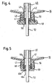
- a first conventional variant is shown, is held in the tubular heater 40 by means of a Isolierperle 58 preferably made of plastic in the mounting hole 46.
- the insulating bead 58 is pushed from the outside to the tubular heater 40 and preferably attached thereto. With the insulating bead 58 of the support ring 56 is firmly connected.
- the solid connection can be effected, for example, by casting the ring 56 in the casting process of the insulating bead 58.
- the function of the support ring 56 of this embodiment and its determination takes place in the same manner as in the support ring 56 in Fig. 3 ,
- the second conventional embodiment shown differs from that in FIG Fig. 4 shown in that the mounting hole 46 has on its outwardly facing end face a constriction 46c, whose inner diameter is approximately the diameter of the connecting bolt 52 of the tubular heater 40 corresponds.
- the tubular heater 40 is inserted from the inside of the housing part 14 or 16 until the end face 40a of the jacket tube of the tubular heater 40 abuts against the constriction 46c.
- the connecting bolt 52 of the Rohrrichgropers 40 passes through the constriction 46c.
- the support ring 56 can be pushed onto the extension 48 from the outside and jammed there, as it is in connection with the Fig. 3 has been explained above.
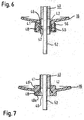
- the conventional embodiment shown differs from the previous one in that the tubular heater 40 is inserted into the mounting opening 46 in such a way that the tubular heater 40 is overmolded during injection of the housing part 14 or 16, so that the mounting opening 46 forms in this injection process.
- the tubular heater 40 may be provided with an overmold seal 50 again.
- a corresponding support ring 56 is provided in order to increase the anchoring of the seal 50 to the tubular heater 40.
- a constriction 42 may be provided on the jacket tube 41 of the tubular heater 40.
- a fourth conventional embodiment is shown, the essential difference from the previous embodiments comprises that the front end 40a of the jacket tube of the tubular heater 40 is widened and at the same time when injecting the housing parts 14 or 16 is inserted into the mounting hole 46.
- the flared end of the jacket tube of the tubular heater 40 is molded directly with plastic, so that the mounting hole 46 is formed during the injection process and the tubular heater 40 is integrated directly into the respective housing part 14 or 16 after the injection process.
- the frontal expansion of the jacket tube can form an acute or obtuse angle with the axis of the mounting hole.
- the jacket tube 7 is the end-side widening funnel-like shape or the expansion of the jacket tube extends to the axial direction of the mounting opening at an acute angle in the direction of the boiler interior.
- the jacket tube has at its front end a larger diameter than the inner diameter of the mounting hole and tapers toward the boiler interior to the normal diameter of the jacket tube.
- the embodiment differs from the Fig. 7 from, for example, the Fig. 4, 5 or 6 on the container inner wall by a directed into the boiler interior extension 48 'in addition to the extension 48 which is directed to the boiler outer wall to the outside.
- the effective strength of the mounting opening is increased, which leads to an improvement in the attachment and support of the jacket tube of the tubular heater 40.
- the wall thickness of the boiler can be dimensioned so that none of the extensions is necessary.
- the tubular heater 40 may be additionally provided with one or more overmold seals similar to the gasket 50 discussed in the other embodiments.
- one or more constrictions (s) similar to the constriction 42, which may be used, for example, in FIG Fig. 6 is shown
- one or more expansion (s) such as the expansion of the tubular casing of the tubular heater of the Fig. 12 ), which in the Fig. 7 are not shown in detail, may be provided on the jacket tube of the tubular heater 40.
- Another option is to provide an additional support ring, similar to the support ring 56 described above, on the extension 48.
- Fig. 8 an embodiment of the invention for a mounting hole 46 and for the embodiment of the attachment of the heater 40 is shown in this.
- the sealing element 50 is inserted in the form of an O-ring.
- the fastener is formed in this embodiment by a clamping sleeve 58, which, as shown in Fig.
- double-walled is formed in such a way that the clamping sleeve 58 can be pushed over the widening 48a of the extension 48 from the outside and the two double-wall forming portions 58a, 58b of the clamping sleeve 58, the wall of the expansion 48a between them.
- the two double-wall forming wall sections 58a, 58b of the clamping sleeve 58 are interconnected by an unspecified bottom, the round contour is adapted in cross-section to the contour of the expansion 48a of the extension 48, as is apparent from Fig. 8 is removable.
- the axial length of the clamping sleeve 58 is selected so that it protrudes beyond the end of the widening 48a of the extension 48 with the outer wall section 58a, which is axially longer than the inner wall section 58b.
- the free end of this wall portion 58a is then, as also out Fig. 8 can be removed, plastically deformed in such a way that the clamping sleeve 58 is fixed to the widening 48 a of the extension 48.
- a Erdungsspeednut 60 is pushed, as is apparent from Fig. 8 emerges, which serves as a ground connection.
- the jacket tube of the heater 40 is closed fluid-tight by an insulating bead 61.
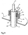
- FIG. 9 The sixth conventional embodiment for a mounting hole 46 is different from that in FIG Fig. 8 shown in that the widening 48a of the extension 48 is not continuous but discontinuous in the form of a substantially radially extending step.
- a double-walled sealing member 62 is used, the opening formed by the two wall portions facing outward.
- the sealing element 62 is adapted at its connecting portion or its bottom of the shape or the step of the expansion 48a.
- a grounding sleeve 63 is inserted, wherein the outwardly facing end face of the grounding sleeve 63 is crimped in the direction of the jacket tube 41 of the tubular heater 40.
- 48b of the support ring 56 is pushed or pressed. It should be noted that in the presentation of the Fig. 9 the insulating bead 61 which is in Fig. 8 is not shown, although it is present in the operational state of the boiler 10.
- the extension 48 has a larger inner diameter than the actual mounting hole 46 in the housing wall of the boiler 10.
- the sealing element 50 is inserted in the between the inner wall of the extension 48, whose outer diameter is greater than the outer diameter of the expansion 40 a of the heater 40, existing space.
- the sealing element 50 can in turn be inserted or sprayed onto the widening 40a of the jacket tube 41, the sealing element 50 also being widened during the production of the widening 40a.
- a sleeve 63 with a grounding flat plug is used, which serves as a ground connection for the heating device 40.
- On the outer side of the extension 48 of the support ring 56 is still provided.
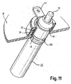
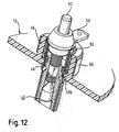
- the in the Fig. 11 and 12 differs from that in FIG Fig. 10 only to the extent that the jacket tube 41 of the heater 40 at the extending from the wall of the housing 12 of the boiler 10 inwardly extending portion has a circumferential recess 40 b, in which the edge of the actual Mounting opening 46 engages. As a result, the heater 40 is axially fixed both in the outward direction and the inward direction.
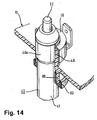
- a further embodiment of the invention is shown, in which an extension 48 is provided not only on the outside of the housing 12 of the boiler 10, but also on the inside of the housing 12.
- This further extension 68 serves to receive or attach a double-walled sealing element 69, which overlaps the extension 68 on both sides.
- the jacket tube 41 of the heater 40 has a widening 40a.
- On the outer extension 48 of the support ring 56 is placed and flanged. This in turn has a grounding flat plug.
- Fig. 16 is another preferably circular mounting opening 70 in the housing 12 of the boiler 10 and in one of the housing parts 14 or 16 reproduced.
- This mounting opening 70 serves to attach a control unit 72 in the housing wall.
- the control unit 72 which preferably has a cylindrical outer contour, is fixed in the mounting opening 70, if necessary with the interposition of a sealing element (not shown), by preferably elastic snap-in lugs 70a which are integrally formed on the outer side of the mounting opening 70.
- the control unit 70 is in heat-conducting contact with the heating device 40 via a corrugated heat conduction plate 74, so that the control unit 70 can detect the temperature of the heating device 70.
- the corrugation of the intoleitblechs 74 serves to compensate for the changes in length during its heating and cooling. It should also be noted that the heat conducting sheet 74 may be fixedly connected to the heater 40 and / or the control unit 72 by a welding or soldering operation.
Landscapes
- Engineering & Computer Science (AREA)
- Physics & Mathematics (AREA)
- Thermal Sciences (AREA)
- Chemical & Material Sciences (AREA)
- Combustion & Propulsion (AREA)
- Mechanical Engineering (AREA)
- General Engineering & Computer Science (AREA)
- Resistance Heating (AREA)
- Instantaneous Water Boilers, Portable Hot-Water Supply Apparatuses, And Control Of Portable Hot-Water Supply Apparatuses (AREA)
Claims (10)
- Chauffe-eau pour réchauffer un milieu susceptible de s'écouler, notamment pour réchauffer de l'eau, comprenantune enveloppe (12) de chauffe-eau en matière plastique,un dispositif (40) de chauffage, qui pénètre par une ouverture (46) de montage de l'enveloppe (12) du chauffe-eau à l'intérieur de l'enveloppe (12) du chauffe-eau et qui est immobilisé dans l'ouverture (46) de montage par des moyens de fixation formés par au moins un élément (56) de serrage, etau moins un élément (50) d'étanchéité, qui est monté entre la paroi intérieure de l'ouverture (46) de montage et la paroi extérieure du dispositif (40) de chauffage, dans lequel le diamètre intérieur de l'ouverture (46) de montage dans l'enveloppe (12) du chauffe-eau correspond, au moins à peu près, au moins par endroit, au diamètre extérieur du dispositif (40) de chauffage,caractériséen ce que le dispositif (40) de chauffage a, au moins dans la zone de l'ouverture (46) de montage, une partie (42) non chauffée, qui se prolonge à l'intérieur de l'enveloppe (12) du chauffe-eau,en ce que l'ouverture (46) de montage pour le dispositif (40) de chauffage est formée par un prolongement (48), qui est monté sur l'enveloppe (12) du chauffe-eau, dont la longueur axiale est plus grande que l'épaisseur de paroi de l'enveloppe (12) du chauffe-eau et qui s'étend vers l'extérieur, de préférence à partir de la paroi de l'enveloppe (12) du chauffe-eau, le moyen de fixationa) étant formé par un manchon (58) de serrage, de manière à ce que le prolongement (48) ait, à son extrémité tournée vers le côté extérieur du chauffe-eau (10), un élargissement (48a) qui fait le tour complètement, dans lequel l'élément (50) d'étanchéité sous la forme d'un joint torique est inséré, le manchon (58) de serrage étant constitué à double paroi, de manière à ce que le manchon (58) de serrage puisse être emmanché de l'extérieur sur l'élargissement (48a) du prolongement (48) et de manière à ce que les deux parties (58a, 58b), formant la double paroi, du manchon (58) de serrage reçoivent entre elles la paroi de l'élargissement (48a), les deux parties (58a, 58b), formant la double paroi, du manchon (58) de serrage étant reliées l'une à l'autre par un fond, dont le contour circulaire en section transversale est adapté au contour de l'élargissement (48a) du prolongement (48), la longueur axiale du manchon (58) de serrage étant choisie, de manière à ce que, par la partie (58a) de paroi se trouvant à l'extérieur et plus longue axialement que la partie (58b) de paroi se trouvant à l'intérieur, il dépasse de l'extrémité de l'élargissement (48a) du prolongement (48), l'extrémité libre de cette partie (58a) de paroi étant alors déformée plastiquement, de manière à fixer le manchon (58) de serrage sur l'élargissement (48a) du prolongement (48) oub) est formé d'une bague (56) d'appui, de manière à ce que, dans la région du prolongement (48), un tube (41) d'enveloppe du dispositif (40) de chauffage ait un élargissement (40a), la bague (56) d'appui étant posée et rabattue sur le prolongement (48) se trouvant à l'extérieur et
en ce que le moyen de fixation peut servir de connexion à la terre, au moins pour le dispositif (40) de chauffage. - Chauffe-eau suivant la revendication 1, caractériséen ce que la partie (42) non chauffée du dispositif (40) de chauffage se prolonge du côté extérieur de l'enveloppe (12) du chauffe-eau, eten ce que la longueur de la partie (42) non chauffée du dispositif (40) de chauffage, dans la direction du côté intérieur de l'enveloppe (12) du chauffe-eau, est plus grande que dans la direction du côté extérieur.
- Chauffe-eau suivant l'une des revendications précédentes, caractériséen ce que l'élément (56) de serrage est immobilisé par déformation plastique du dispositif (40) de chauffage dans l'ouverture (46) de montage pour le dispositif de chauffage.
- Chauffe-eau suivant l'une des revendications 1 à 3, caractériséen ce qu'au moins une autre ouverture (70) de montage est prévue pour le montage d'au moins une unité (72) de commande, qui est en contact de conduction de la chaleur avec une partie chauffée du dispositif (40) de chauffage, le contact de conduction de la chaleur s'effectuant par conduction de la chaleur par un élément (74) conducteur de la chaleur, de préférence une tôle de conduction de la chaleur.
- Chauffe-eau suivant la revendication 4, caractériséen ce que l'unité (72) de commande est formée par un élément PTC, par un élément NTC, par un fusible ou par un régleur.
- Chauffe-eau suivant l'une des revendications 4 ou 5, caractériséen ce que l'unité (72) de commande est maintenue dans l'ouverture (46) de montage par une opération d'encliquetage et/ou par des éléments (70a) de fixation.
- Chauffe-eau suivant l'une des revendications 1 à 6, caractériséen ce que l'enveloppe (12) du chauffe-eau est constituée d'au moins deux parties (14, 16),la au moins une ouverture (46) de montage étant prévue dans l'une des deux parties (14, 16) de l'enveloppe du chauffe-eau.
- Chauffe-eau suivant la revendication 7, dans lequelles deux parties (14, 16) de l'enveloppe sont reliées entre elles à complémentarité de matière, à complémentarité de forme ou à complémentarité de force avec interposition d'au moins une étanchéité (22) sur les surfaces de joint des parties (14, 16) de l'enveloppe.
- Chauffe-eau suivant l'une des revendications 1 à 8, caractériséen ce que le dispositif de chauffage est un radiateur (40) tubulaire.
- Chauffe-eau suivant la revendication 1, caractériséen ce qu'un autre prolongement (48', 68) est monté sur l'ouverture (46) de montage du côté intérieur de l'enveloppe du chauffe-eau.
Applications Claiming Priority (1)
| Application Number | Priority Date | Filing Date | Title |
|---|---|---|---|
| DE10526919 | 2005-06-10 |
Publications (4)
| Publication Number | Publication Date |
|---|---|
| EP1731850A2 EP1731850A2 (fr) | 2006-12-13 |
| EP1731850A3 EP1731850A3 (fr) | 2009-05-13 |
| EP1731850B1 EP1731850B1 (fr) | 2013-02-13 |
| EP1731850B2 true EP1731850B2 (fr) | 2016-08-17 |
Family
ID=36910977
Family Applications (1)
| Application Number | Title | Priority Date | Filing Date |
|---|---|---|---|
| EP06011532.6A Not-in-force EP1731850B2 (fr) | 2005-06-10 | 2006-06-02 | Chaudière en matière plastique sans bride |
Country Status (1)
| Country | Link |
|---|---|
| EP (1) | EP1731850B2 (fr) |
Families Citing this family (4)
| Publication number | Priority date | Publication date | Assignee | Title |
|---|---|---|---|---|
| DE102017124062A1 (de) | 2017-10-16 | 2019-04-18 | Bleckmann Gmbh & Co. Kg | Dampfgenerator mit Sicherheitstemperaturbegrenzervorrichtung |
| FR3103885B1 (fr) * | 2019-11-29 | 2021-12-24 | Soc Commerciale Et Dengineering | Réservoir de liquide apte à être chauffé |
| CA3158093A1 (fr) * | 2019-11-29 | 2021-06-03 | Societe Commerciale Et D'engineering | Reservoir de liquide apte a etre chauffe |
| EP3936007A1 (fr) | 2020-07-09 | 2022-01-12 | Bleckmann GmbH & Co. KG | Dispositif de génération de vapeur et d'eau chaude |
Citations (9)
| Publication number | Priority date | Publication date | Assignee | Title |
|---|---|---|---|---|
| US2748251A (en) † | 1953-04-20 | 1956-05-29 | Wiegand Co Edwin L | Heating devices |
| US3134888A (en) † | 1960-12-19 | 1964-05-26 | Wiegand Co Edwin L | Immersion heater assemblies |
| FR2088630A5 (fr) † | 1970-04-20 | 1972-01-07 | Pyror Procedes | |
| CA1019026A (en) † | 1973-11-05 | 1977-10-11 | Carl G. Strobach | Immersion type heating element with a plastic head for a storage water heater tank |
| DE3333698A1 (de) † | 1983-09-17 | 1985-04-04 | Stiebel Eltron Gmbh & Co Kg, 3450 Holzminden | Befestigungseinrichtung eines elektrischen rohrheizkoerpers und verfahren zu deren herstellung |
| DE3804326A1 (de) † | 1988-02-12 | 1989-08-24 | Ego Elektro Blanc & Fischer | Endstueck fuer rohrheizkoerper |
| EP1211466A2 (fr) † | 1997-12-29 | 2002-06-05 | MERLONI TERMOSANITARI S.p.A. | Chauffe-eau en matière plastique résistant à la pression |
| WO2003002919A1 (fr) † | 2001-06-26 | 2003-01-09 | BSH Bosch und Siemens Hausgeräte GmbH | Chauffe-eau electrique |
| WO2004083738A1 (fr) † | 2003-03-21 | 2004-09-30 | BSH Bosch und Siemens Hausgeräte GmbH | Chauffe-eau |
Family Cites Families (2)
| Publication number | Priority date | Publication date | Assignee | Title |
|---|---|---|---|---|
| DE7512731U (de) * | 1975-10-23 | Stiebel Eltron Gmbh & Co Kg | Behälter für einen Heißwasserbereiter | |
| GB9322526D0 (en) * | 1993-11-02 | 1993-12-22 | Strix Ltd | Electrical heaters |
-
2006
- 2006-06-02 EP EP06011532.6A patent/EP1731850B2/fr not_active Not-in-force
Patent Citations (9)
| Publication number | Priority date | Publication date | Assignee | Title |
|---|---|---|---|---|
| US2748251A (en) † | 1953-04-20 | 1956-05-29 | Wiegand Co Edwin L | Heating devices |
| US3134888A (en) † | 1960-12-19 | 1964-05-26 | Wiegand Co Edwin L | Immersion heater assemblies |
| FR2088630A5 (fr) † | 1970-04-20 | 1972-01-07 | Pyror Procedes | |
| CA1019026A (en) † | 1973-11-05 | 1977-10-11 | Carl G. Strobach | Immersion type heating element with a plastic head for a storage water heater tank |
| DE3333698A1 (de) † | 1983-09-17 | 1985-04-04 | Stiebel Eltron Gmbh & Co Kg, 3450 Holzminden | Befestigungseinrichtung eines elektrischen rohrheizkoerpers und verfahren zu deren herstellung |
| DE3804326A1 (de) † | 1988-02-12 | 1989-08-24 | Ego Elektro Blanc & Fischer | Endstueck fuer rohrheizkoerper |
| EP1211466A2 (fr) † | 1997-12-29 | 2002-06-05 | MERLONI TERMOSANITARI S.p.A. | Chauffe-eau en matière plastique résistant à la pression |
| WO2003002919A1 (fr) † | 2001-06-26 | 2003-01-09 | BSH Bosch und Siemens Hausgeräte GmbH | Chauffe-eau electrique |
| WO2004083738A1 (fr) † | 2003-03-21 | 2004-09-30 | BSH Bosch und Siemens Hausgeräte GmbH | Chauffe-eau |
Non-Patent Citations (1)
| Title |
|---|
| Wikipediaeintrag "Rohrheizkörper" † |
Also Published As
| Publication number | Publication date |
|---|---|
| EP1731850A2 (fr) | 2006-12-13 |
| EP1731850B1 (fr) | 2013-02-13 |
| EP1731850A3 (fr) | 2009-05-13 |
Similar Documents
| Publication | Publication Date | Title |
|---|---|---|
| EP2296433B1 (fr) | Dispositif de chauffage électrique et procédé de fabrication d'un dispositif de chauffage électrique | |
| EP2637475B1 (fr) | Elément chauffant | |
| EP1816901B1 (fr) | Radiateur doté d'une masse d'isolation dans la zone d'extrémité de raccordement | |
| EP2407069A1 (fr) | Chauffe-eau instantané dynamique | |
| EP2211588B1 (fr) | Elément de contact pour spirale chauffante d'un élément chauffant tubulaire et son procédé de fabrication | |
| EP2637474A1 (fr) | Elément chauffant | |
| EP2171336B1 (fr) | Raccord tubulaire doté d'un boîtier pour robinetterie | |
| EP1731850B2 (fr) | Chaudière en matière plastique sans bride | |
| DE102005026919A1 (de) | Flanschloser Kunststoff-Boiler | |
| DE3443306C1 (de) | Elektrischer Patronenheizkoerper | |
| DE10349925A1 (de) | Einbauventil für einen Heizkörper, insbesondere Gliederheizkörper | |
| DE60000640T2 (de) | Bürstenhaltermontage für elektrische maschinen wie kfz-anlasser | |
| EP1816899B1 (fr) | Collet à cliquet | |
| EP1995994B1 (fr) | Dispositif de chauffage électrique | |
| DE10336776B4 (de) | Einfüllstutzen für den Kraftstoffbehälter eines Kraftfahrzeuges mit einem automatischen Tankverschluss | |
| DE102009024059A1 (de) | Durchlauferhitzer | |
| EP3023039B1 (fr) | Corps de chauffage, chauffe-eau instantané pour machines à boissons chaudes et son procédé de fabrication | |
| EP3843502B1 (fr) | Dispositif de chauffage électrique | |
| EP1541069A1 (fr) | Bouilloire | |
| DE102011000246A1 (de) | Heizeinrichtung | |
| EP1111962B1 (fr) | Dispositif de chauffage possédant une enveloppe tubulaire divisée | |
| DE10062539B4 (de) | Anschlußbaugruppe für eine elektrische Heizvorrichtung sowie Verfahren zur Montage der Heizvorrichtung | |
| DE202010011994U1 (de) | Boiler mit lötfreier Durchführung für Heizkörperanschlussendabschnitte | |
| DE202018105899U1 (de) | Elektrische Bauteilheizung | |
| DE102018121047A1 (de) | Verbindungsanordnung eines Rohranschlusses an einem Haustechnikgerät sowie Haustechnikgerät mit einer solchen Verbindungsanordnung |
Legal Events
| Date | Code | Title | Description |
|---|---|---|---|
| PUAI | Public reference made under article 153(3) epc to a published international application that has entered the european phase |
Free format text: ORIGINAL CODE: 0009012 |
|
| AK | Designated contracting states |
Kind code of ref document: A2 Designated state(s): AT BE BG CH CY CZ DE DK EE ES FI FR GB GR HU IE IS IT LI LT LU LV MC NL PL PT RO SE SI SK TR |
|
| AX | Request for extension of the european patent |
Extension state: AL BA HR MK YU |
|
| PUAL | Search report despatched |
Free format text: ORIGINAL CODE: 0009013 |
|
| AK | Designated contracting states |
Kind code of ref document: A3 Designated state(s): AT BE BG CH CY CZ DE DK EE ES FI FR GB GR HU IE IS IT LI LT LU LV MC NL PL PT RO SE SI SK TR |
|
| AX | Request for extension of the european patent |
Extension state: AL BA HR MK YU |
|
| 17P | Request for examination filed |
Effective date: 20091002 |
|
| AKX | Designation fees paid |
Designated state(s): AT BE BG CH CY CZ DE DK EE ES FI FR GB GR HU IE IS IT LI LT LU LV MC NL PL PT RO SE SI SK TR |
|
| 17Q | First examination report despatched |
Effective date: 20100304 |
|
| REG | Reference to a national code |
Ref country code: DE Ref legal event code: R079 Ref document number: 502006012480 Country of ref document: DE Free format text: PREVIOUS MAIN CLASS: F24H0001200000 Ipc: F24H0009180000 |
|
| RIC1 | Information provided on ipc code assigned before grant |
Ipc: F24H 9/18 20060101AFI20120712BHEP Ipc: F24H 1/20 20060101ALI20120712BHEP |
|
| GRAP | Despatch of communication of intention to grant a patent |
Free format text: ORIGINAL CODE: EPIDOSNIGR1 |
|
| GRAS | Grant fee paid |
Free format text: ORIGINAL CODE: EPIDOSNIGR3 |
|
| GRAA | (expected) grant |
Free format text: ORIGINAL CODE: 0009210 |
|
| AK | Designated contracting states |
Kind code of ref document: B1 Designated state(s): AT BE BG CH CY CZ DE DK EE ES FI FR GB GR HU IE IS IT LI LT LU LV MC NL PL PT RO SE SI SK TR |
|
| REG | Reference to a national code |
Ref country code: GB Ref legal event code: FG4D Free format text: NOT ENGLISH |
|
| RIN1 | Information on inventor provided before grant (corrected) |
Inventor name: HENDLER, RENE Inventor name: PLESCHINGER, ANDREAS Inventor name: HOEFER, JOHANN |
|
| REG | Reference to a national code |
Ref country code: AT Ref legal event code: REF Ref document number: 596711 Country of ref document: AT Kind code of ref document: T Effective date: 20130215 |
|
| REG | Reference to a national code |
Ref country code: IE Ref legal event code: FG4D Free format text: LANGUAGE OF EP DOCUMENT: GERMAN |
|
| REG | Reference to a national code |
Ref country code: DE Ref legal event code: R096 Ref document number: 502006012480 Country of ref document: DE Effective date: 20130411 |
|
| REG | Reference to a national code |
Ref country code: NL Ref legal event code: T3 |
|
| REG | Reference to a national code |
Ref country code: LT Ref legal event code: MG4D |
|
| PG25 | Lapsed in a contracting state [announced via postgrant information from national office to epo] |
Ref country code: SE Free format text: LAPSE BECAUSE OF FAILURE TO SUBMIT A TRANSLATION OF THE DESCRIPTION OR TO PAY THE FEE WITHIN THE PRESCRIBED TIME-LIMIT Effective date: 20130213 Ref country code: LT Free format text: LAPSE BECAUSE OF FAILURE TO SUBMIT A TRANSLATION OF THE DESCRIPTION OR TO PAY THE FEE WITHIN THE PRESCRIBED TIME-LIMIT Effective date: 20130213 Ref country code: BG Free format text: LAPSE BECAUSE OF FAILURE TO SUBMIT A TRANSLATION OF THE DESCRIPTION OR TO PAY THE FEE WITHIN THE PRESCRIBED TIME-LIMIT Effective date: 20130513 Ref country code: IS Free format text: LAPSE BECAUSE OF FAILURE TO SUBMIT A TRANSLATION OF THE DESCRIPTION OR TO PAY THE FEE WITHIN THE PRESCRIBED TIME-LIMIT Effective date: 20130613 Ref country code: ES Free format text: LAPSE BECAUSE OF FAILURE TO SUBMIT A TRANSLATION OF THE DESCRIPTION OR TO PAY THE FEE WITHIN THE PRESCRIBED TIME-LIMIT Effective date: 20130524 |
|
| PG25 | Lapsed in a contracting state [announced via postgrant information from national office to epo] |
Ref country code: FI Free format text: LAPSE BECAUSE OF FAILURE TO SUBMIT A TRANSLATION OF THE DESCRIPTION OR TO PAY THE FEE WITHIN THE PRESCRIBED TIME-LIMIT Effective date: 20130213 Ref country code: SI Free format text: LAPSE BECAUSE OF FAILURE TO SUBMIT A TRANSLATION OF THE DESCRIPTION OR TO PAY THE FEE WITHIN THE PRESCRIBED TIME-LIMIT Effective date: 20130213 Ref country code: PL Free format text: LAPSE BECAUSE OF FAILURE TO SUBMIT A TRANSLATION OF THE DESCRIPTION OR TO PAY THE FEE WITHIN THE PRESCRIBED TIME-LIMIT Effective date: 20130213 Ref country code: PT Free format text: LAPSE BECAUSE OF FAILURE TO SUBMIT A TRANSLATION OF THE DESCRIPTION OR TO PAY THE FEE WITHIN THE PRESCRIBED TIME-LIMIT Effective date: 20130613 Ref country code: LV Free format text: LAPSE BECAUSE OF FAILURE TO SUBMIT A TRANSLATION OF THE DESCRIPTION OR TO PAY THE FEE WITHIN THE PRESCRIBED TIME-LIMIT Effective date: 20130213 Ref country code: GR Free format text: LAPSE BECAUSE OF FAILURE TO SUBMIT A TRANSLATION OF THE DESCRIPTION OR TO PAY THE FEE WITHIN THE PRESCRIBED TIME-LIMIT Effective date: 20130514 |
|
| PG25 | Lapsed in a contracting state [announced via postgrant information from national office to epo] |
Ref country code: SK Free format text: LAPSE BECAUSE OF FAILURE TO SUBMIT A TRANSLATION OF THE DESCRIPTION OR TO PAY THE FEE WITHIN THE PRESCRIBED TIME-LIMIT Effective date: 20130213 Ref country code: CZ Free format text: LAPSE BECAUSE OF FAILURE TO SUBMIT A TRANSLATION OF THE DESCRIPTION OR TO PAY THE FEE WITHIN THE PRESCRIBED TIME-LIMIT Effective date: 20130213 Ref country code: DK Free format text: LAPSE BECAUSE OF FAILURE TO SUBMIT A TRANSLATION OF THE DESCRIPTION OR TO PAY THE FEE WITHIN THE PRESCRIBED TIME-LIMIT Effective date: 20130213 Ref country code: RO Free format text: LAPSE BECAUSE OF FAILURE TO SUBMIT A TRANSLATION OF THE DESCRIPTION OR TO PAY THE FEE WITHIN THE PRESCRIBED TIME-LIMIT Effective date: 20130213 Ref country code: EE Free format text: LAPSE BECAUSE OF FAILURE TO SUBMIT A TRANSLATION OF THE DESCRIPTION OR TO PAY THE FEE WITHIN THE PRESCRIBED TIME-LIMIT Effective date: 20130213 |
|
| PLBI | Opposition filed |
Free format text: ORIGINAL CODE: 0009260 |
|
| 26 | Opposition filed |
Opponent name: STIEBEL ELTRON GMBH & CO. KG Effective date: 20131113 |
|
| BERE | Be: lapsed |
Owner name: BLECKMANN GMBH & CO. KG Effective date: 20130630 |
|
| PLAX | Notice of opposition and request to file observation + time limit sent |
Free format text: ORIGINAL CODE: EPIDOSNOBS2 |
|
| PG25 | Lapsed in a contracting state [announced via postgrant information from national office to epo] |
Ref country code: MC Free format text: LAPSE BECAUSE OF FAILURE TO SUBMIT A TRANSLATION OF THE DESCRIPTION OR TO PAY THE FEE WITHIN THE PRESCRIBED TIME-LIMIT Effective date: 20130213 |
|
| REG | Reference to a national code |
Ref country code: CH Ref legal event code: PL |
|
| REG | Reference to a national code |
Ref country code: DE Ref legal event code: R026 Ref document number: 502006012480 Country of ref document: DE Effective date: 20131113 |
|
| GBPC | Gb: european patent ceased through non-payment of renewal fee |
Effective date: 20130602 |
|
| REG | Reference to a national code |
Ref country code: IE Ref legal event code: MM4A |
|
| PG25 | Lapsed in a contracting state [announced via postgrant information from national office to epo] |
Ref country code: BE Free format text: LAPSE BECAUSE OF NON-PAYMENT OF DUE FEES Effective date: 20130630 |
|
| PG25 | Lapsed in a contracting state [announced via postgrant information from national office to epo] |
Ref country code: CH Free format text: LAPSE BECAUSE OF NON-PAYMENT OF DUE FEES Effective date: 20130630 Ref country code: LI Free format text: LAPSE BECAUSE OF NON-PAYMENT OF DUE FEES Effective date: 20130630 Ref country code: GB Free format text: LAPSE BECAUSE OF NON-PAYMENT OF DUE FEES Effective date: 20130602 Ref country code: IE Free format text: LAPSE BECAUSE OF NON-PAYMENT OF DUE FEES Effective date: 20130602 |
|
| PLBB | Reply of patent proprietor to notice(s) of opposition received |
Free format text: ORIGINAL CODE: EPIDOSNOBS3 |
|
| REG | Reference to a national code |
Ref country code: AT Ref legal event code: MM01 Ref document number: 596711 Country of ref document: AT Kind code of ref document: T Effective date: 20130602 |
|
| PG25 | Lapsed in a contracting state [announced via postgrant information from national office to epo] |
Ref country code: AT Free format text: LAPSE BECAUSE OF NON-PAYMENT OF DUE FEES Effective date: 20130602 |
|
| PG25 | Lapsed in a contracting state [announced via postgrant information from national office to epo] |
Ref country code: TR Free format text: LAPSE BECAUSE OF FAILURE TO SUBMIT A TRANSLATION OF THE DESCRIPTION OR TO PAY THE FEE WITHIN THE PRESCRIBED TIME-LIMIT Effective date: 20130213 Ref country code: CY Free format text: LAPSE BECAUSE OF FAILURE TO SUBMIT A TRANSLATION OF THE DESCRIPTION OR TO PAY THE FEE WITHIN THE PRESCRIBED TIME-LIMIT Effective date: 20130213 |
|
| PG25 | Lapsed in a contracting state [announced via postgrant information from national office to epo] |
Ref country code: LU Free format text: LAPSE BECAUSE OF NON-PAYMENT OF DUE FEES Effective date: 20130602 Ref country code: HU Free format text: LAPSE BECAUSE OF FAILURE TO SUBMIT A TRANSLATION OF THE DESCRIPTION OR TO PAY THE FEE WITHIN THE PRESCRIBED TIME-LIMIT; INVALID AB INITIO Effective date: 20060602 |
|
| APBM | Appeal reference recorded |
Free format text: ORIGINAL CODE: EPIDOSNREFNO |
|
| APBP | Date of receipt of notice of appeal recorded |
Free format text: ORIGINAL CODE: EPIDOSNNOA2O |
|
| APAH | Appeal reference modified |
Free format text: ORIGINAL CODE: EPIDOSCREFNO |
|
| APBU | Appeal procedure closed |
Free format text: ORIGINAL CODE: EPIDOSNNOA9O |
|
| REG | Reference to a national code |
Ref country code: FR Ref legal event code: PLFP Year of fee payment: 11 |
|
| PUAH | Patent maintained in amended form |
Free format text: ORIGINAL CODE: 0009272 |
|
| STAA | Information on the status of an ep patent application or granted ep patent |
Free format text: STATUS: PATENT MAINTAINED AS AMENDED |
|
| 27A | Patent maintained in amended form |
Effective date: 20160817 |
|
| AK | Designated contracting states |
Kind code of ref document: B2 Designated state(s): AT BE BG CH CY CZ DE DK EE ES FI FR GB GR HU IE IS IT LI LT LU LV MC NL PL PT RO SE SI SK TR |
|
| REG | Reference to a national code |
Ref country code: DE Ref legal event code: R102 Ref document number: 502006012480 Country of ref document: DE |
|
| REG | Reference to a national code |
Ref country code: NL Ref legal event code: FP |
|
| REG | Reference to a national code |
Ref country code: FR Ref legal event code: PLFP Year of fee payment: 12 |
|
| REG | Reference to a national code |
Ref country code: FR Ref legal event code: PLFP Year of fee payment: 13 |
|
| PGFP | Annual fee paid to national office [announced via postgrant information from national office to epo] |
Ref country code: NL Payment date: 20180625 Year of fee payment: 13 |
|
| PGFP | Annual fee paid to national office [announced via postgrant information from national office to epo] |
Ref country code: FR Payment date: 20180625 Year of fee payment: 13 |
|
| PGFP | Annual fee paid to national office [announced via postgrant information from national office to epo] |
Ref country code: IE Payment date: 20180816 Year of fee payment: 12 |
|
| REG | Reference to a national code |
Ref country code: NL Ref legal event code: MM Effective date: 20190701 |
|
| PG25 | Lapsed in a contracting state [announced via postgrant information from national office to epo] |
Ref country code: NL Free format text: LAPSE BECAUSE OF NON-PAYMENT OF DUE FEES Effective date: 20190701 Ref country code: IT Free format text: LAPSE BECAUSE OF NON-PAYMENT OF DUE FEES Effective date: 20190602 |
|
| PG25 | Lapsed in a contracting state [announced via postgrant information from national office to epo] |
Ref country code: FR Free format text: LAPSE BECAUSE OF NON-PAYMENT OF DUE FEES Effective date: 20190630 |
|
| P01 | Opt-out of the competence of the unified patent court (upc) registered |
Effective date: 20230517 |
|
| PGFP | Annual fee paid to national office [announced via postgrant information from national office to epo] |
Ref country code: DE Payment date: 20240704 Year of fee payment: 19 |
|
| REG | Reference to a national code |
Ref country code: DE Ref legal event code: R119 Ref document number: 502006012480 Country of ref document: DE |
|
| PG25 | Lapsed in a contracting state [announced via postgrant information from national office to epo] |
Ref country code: DE Free format text: LAPSE BECAUSE OF NON-PAYMENT OF DUE FEES Effective date: 20260101 |