EP1731864A1 - Echangeur de chaleur métallique et procédé de fabrication de celui-ci - Google Patents
Echangeur de chaleur métallique et procédé de fabrication de celui-ci Download PDFInfo
- Publication number
- EP1731864A1 EP1731864A1 EP05012589A EP05012589A EP1731864A1 EP 1731864 A1 EP1731864 A1 EP 1731864A1 EP 05012589 A EP05012589 A EP 05012589A EP 05012589 A EP05012589 A EP 05012589A EP 1731864 A1 EP1731864 A1 EP 1731864A1
- Authority
- EP
- European Patent Office
- Prior art keywords
- projections
- flat tubes
- heat exchanger
- tube
- metal heat
- Prior art date
- Legal status (The legal status is an assumption and is not a legal conclusion. Google has not performed a legal analysis and makes no representation as to the accuracy of the status listed.)
- Withdrawn
Links
- 238000004519 manufacturing process Methods 0.000 title claims abstract description 12
- 238000000034 method Methods 0.000 title abstract description 9
- 229910052751 metal Inorganic materials 0.000 claims abstract description 22
- 239000002184 metal Substances 0.000 claims abstract description 22
- IHQKEDIOMGYHEB-UHFFFAOYSA-M sodium dimethylarsinate Chemical class [Na+].C[As](C)([O-])=O IHQKEDIOMGYHEB-UHFFFAOYSA-M 0.000 claims description 7
- 230000001747 exhibiting effect Effects 0.000 claims 1
- 230000015572 biosynthetic process Effects 0.000 abstract 2
- 238000005755 formation reaction Methods 0.000 abstract 2
- 238000005476 soldering Methods 0.000 description 8
- 230000008569 process Effects 0.000 description 7
- 230000008901 benefit Effects 0.000 description 5
- 229910000679 solder Inorganic materials 0.000 description 5
- 230000002349 favourable effect Effects 0.000 description 3
- 238000005219 brazing Methods 0.000 description 2
- 238000013461 design Methods 0.000 description 2
- 230000000694 effects Effects 0.000 description 2
- 238000003780 insertion Methods 0.000 description 2
- 230000037431 insertion Effects 0.000 description 2
- 229910000838 Al alloy Inorganic materials 0.000 description 1
- 229910052782 aluminium Inorganic materials 0.000 description 1
- XAGFODPZIPBFFR-UHFFFAOYSA-N aluminium Chemical compound [Al] XAGFODPZIPBFFR-UHFFFAOYSA-N 0.000 description 1
- 238000013459 approach Methods 0.000 description 1
- 238000006243 chemical reaction Methods 0.000 description 1
- 238000010276 construction Methods 0.000 description 1
- 238000001816 cooling Methods 0.000 description 1
- 238000005516 engineering process Methods 0.000 description 1
- 230000004048 modification Effects 0.000 description 1
- 238000012986 modification Methods 0.000 description 1
- 230000035515 penetration Effects 0.000 description 1
- 230000009467 reduction Effects 0.000 description 1
- 230000000717 retained effect Effects 0.000 description 1
- 238000001228 spectrum Methods 0.000 description 1
Images


Classifications
-
- F—MECHANICAL ENGINEERING; LIGHTING; HEATING; WEAPONS; BLASTING
- F28—HEAT EXCHANGE IN GENERAL
- F28F—DETAILS OF HEAT-EXCHANGE AND HEAT-TRANSFER APPARATUS, OF GENERAL APPLICATION
- F28F21/00—Constructions of heat-exchange apparatus characterised by the selection of particular materials
- F28F21/08—Constructions of heat-exchange apparatus characterised by the selection of particular materials of metal
- F28F21/081—Heat exchange elements made from metals or metal alloys
- F28F21/084—Heat exchange elements made from metals or metal alloys from aluminium or aluminium alloys
-
- B—PERFORMING OPERATIONS; TRANSPORTING
- B21—MECHANICAL METAL-WORKING WITHOUT ESSENTIALLY REMOVING MATERIAL; PUNCHING METAL
- B21D—WORKING OR PROCESSING OF SHEET METAL OR METAL TUBES, RODS OR PROFILES WITHOUT ESSENTIALLY REMOVING MATERIAL; PUNCHING METAL
- B21D53/00—Making other particular articles
- B21D53/02—Making other particular articles heat exchangers or parts thereof, e.g. radiators, condensers fins, headers
- B21D53/08—Making other particular articles heat exchangers or parts thereof, e.g. radiators, condensers fins, headers of both metal tubes and sheet metal
- B21D53/085—Making other particular articles heat exchangers or parts thereof, e.g. radiators, condensers fins, headers of both metal tubes and sheet metal with fins places on zig-zag tubes or parallel tubes
-
- F—MECHANICAL ENGINEERING; LIGHTING; HEATING; WEAPONS; BLASTING
- F28—HEAT EXCHANGE IN GENERAL
- F28D—HEAT-EXCHANGE APPARATUS, NOT PROVIDED FOR IN ANOTHER SUBCLASS, IN WHICH THE HEAT-EXCHANGE MEDIA DO NOT COME INTO DIRECT CONTACT
- F28D1/00—Heat-exchange apparatus having stationary conduit assemblies for one heat-exchange medium only, the media being in contact with different sides of the conduit wall, in which the other heat-exchange medium is a large body of fluid, e.g. domestic or motor car radiators
- F28D1/02—Heat-exchange apparatus having stationary conduit assemblies for one heat-exchange medium only, the media being in contact with different sides of the conduit wall, in which the other heat-exchange medium is a large body of fluid, e.g. domestic or motor car radiators with heat-exchange conduits immersed in the body of fluid
- F28D1/04—Heat-exchange apparatus having stationary conduit assemblies for one heat-exchange medium only, the media being in contact with different sides of the conduit wall, in which the other heat-exchange medium is a large body of fluid, e.g. domestic or motor car radiators with heat-exchange conduits immersed in the body of fluid with tubular conduits
- F28D1/053—Heat-exchange apparatus having stationary conduit assemblies for one heat-exchange medium only, the media being in contact with different sides of the conduit wall, in which the other heat-exchange medium is a large body of fluid, e.g. domestic or motor car radiators with heat-exchange conduits immersed in the body of fluid with tubular conduits the conduits being straight
- F28D1/0535—Heat-exchange apparatus having stationary conduit assemblies for one heat-exchange medium only, the media being in contact with different sides of the conduit wall, in which the other heat-exchange medium is a large body of fluid, e.g. domestic or motor car radiators with heat-exchange conduits immersed in the body of fluid with tubular conduits the conduits being straight the conduits having a non-circular cross-section
- F28D1/05366—Assemblies of conduits connected to common headers, e.g. core type radiators
-
- F—MECHANICAL ENGINEERING; LIGHTING; HEATING; WEAPONS; BLASTING
- F28—HEAT EXCHANGE IN GENERAL
- F28F—DETAILS OF HEAT-EXCHANGE AND HEAT-TRANSFER APPARATUS, OF GENERAL APPLICATION
- F28F13/00—Arrangements for modifying heat-transfer, e.g. increasing, decreasing
- F28F13/06—Arrangements for modifying heat-transfer, e.g. increasing, decreasing by affecting the pattern of flow of the heat-exchange media
-
- F—MECHANICAL ENGINEERING; LIGHTING; HEATING; WEAPONS; BLASTING
- F28—HEAT EXCHANGE IN GENERAL
- F28F—DETAILS OF HEAT-EXCHANGE AND HEAT-TRANSFER APPARATUS, OF GENERAL APPLICATION
- F28F3/00—Plate-like or laminated elements; Assemblies of plate-like or laminated elements
- F28F3/02—Elements or assemblies thereof with means for increasing heat-transfer area, e.g. with fins, with recesses, with corrugations
- F28F3/025—Elements or assemblies thereof with means for increasing heat-transfer area, e.g. with fins, with recesses, with corrugations the means being corrugated, plate-like elements
-
- F—MECHANICAL ENGINEERING; LIGHTING; HEATING; WEAPONS; BLASTING
- F28—HEAT EXCHANGE IN GENERAL
- F28F—DETAILS OF HEAT-EXCHANGE AND HEAT-TRANSFER APPARATUS, OF GENERAL APPLICATION
- F28F9/00—Casings; Header boxes; Auxiliary supports for elements; Auxiliary members within casings
- F28F9/001—Casings in the form of plate-like arrangements; Frames enclosing a heat exchange core
-
- F—MECHANICAL ENGINEERING; LIGHTING; HEATING; WEAPONS; BLASTING
- F28—HEAT EXCHANGE IN GENERAL
- F28F—DETAILS OF HEAT-EXCHANGE AND HEAT-TRANSFER APPARATUS, OF GENERAL APPLICATION
- F28F9/00—Casings; Header boxes; Auxiliary supports for elements; Auxiliary members within casings
- F28F9/02—Header boxes; End plates
- F28F9/0219—Arrangements for sealing end plates into casing or header box; Header box sub-elements
- F28F9/0224—Header boxes formed by sealing end plates into covers
-
- F—MECHANICAL ENGINEERING; LIGHTING; HEATING; WEAPONS; BLASTING
- F28—HEAT EXCHANGE IN GENERAL
- F28D—HEAT-EXCHANGE APPARATUS, NOT PROVIDED FOR IN ANOTHER SUBCLASS, IN WHICH THE HEAT-EXCHANGE MEDIA DO NOT COME INTO DIRECT CONTACT
- F28D21/00—Heat-exchange apparatus not covered by any of the groups F28D1/00 - F28D20/00
- F28D2021/0019—Other heat exchangers for particular applications; Heat exchange systems not otherwise provided for
- F28D2021/008—Other heat exchangers for particular applications; Heat exchange systems not otherwise provided for for vehicles
- F28D2021/0082—Charged air coolers
Definitions
- the invention relates to a whole-metal heat exchanger, consisting of flat tubes and ribs, which form a block and at least one tube plate and a collecting box, wherein preferably at edges of the collecting tank at intervals arranged projections are arranged, which serve for mounting the heat exchanger. Furthermore, a manufacturing method for whole-metal heat exchangers is proposed.
- the heat exchanger described above is for example from the DE 198 19 247 A1 known.
- the projections correspond there with openings in the tube sheets.
- a provisional cohesion of the items is provided before performing the soldering process.
- the cost of soldering auxiliary device can be significantly reduced.
- a certain disadvantage of the known heat exchanger is that there is still a clear overhang of the tube bottom over the rib-flat tube block, which could be regarded as an unnecessary space requirement.
- the ratio of the cross sections occupied by the flat tubes is not optimal in comparison with the entire cross section of the heat exchanger or its tube plates, so that improvements are possible with regard to efficient heat exchange.
- the object of the invention is to provide a heat exchanger which achieves a smaller space requirement with comparatively good thermal-technical values.
- the solution according to the invention results with respect to the all-metal heat exchanger by the use of the features of claim 1.
- the production method according to the invention is the subject of claim 14. It is envisaged that the projections in the region of the narrow sides engage in the ends of the flat tubes. The projections are preferably located on the opposite longitudinal edges of the header tank.
- embodiments may be provided, in which the projections are arranged on the longitudinal edges of the tube sheet, possibly associated with the disadvantage that the tube sheets are expensive and some other advantages do not occur.
- Another possible construction is that a metallic, frame-like additional part, which has the projections, is provided.
- the manufacturing process leads to a number of advantages.
- the plugged into the flat tube ends projections on both opposite edges of the header hold the flat tubes during the subsequent soldering process to tension, so that the risk of so-called "collapse" of the flat tubes, with the result of insufficient solder joints with the tube sheet has been substantially reduced.
- the invention therefore also allows the use of flat tubes, the broad sides of which may have larger dimensions and thus avoids the production-technically complicated use of several Flachroh marinan in the direction of the depth of the flat-tube rib block.
- heat exchangers can be made available in a much broader performance spectrum with much less modification effort.
- the flat tubes extend over the entire depth of the tubesheet, preferably even beyond, there is virtually no space that would not be available for heat exchange purposes.
- the flow-through cross-sectional area of the flat tubes is in a more favorable ratio to the total occupied by the tube sheet surface, which in turn is about equal to the relevant area, which is occupied by the entire heat exchanger.
- the proposed heat exchanger has a higher process reliability in the production, as heat exchangers, which have no tube plates but instead of the tubesheets flared flat tube ends, as for example from DE 195 43 986 A1 or from much older documents are known.
- the first-mentioned alternative is, as mentioned, preferred, because it is better to prevent the already mentioned "collapse" of the flat tubes, since in this case the Edge of the headers with the projections from the outside rests on the edge of the tube sheet and therefore because the projections against forces acting in the direction of the broad side, ie transversely to the longitudinal direction of the flat tubes, are particularly resistant. Furthermore, this alternative also appears to be more favorable in terms of creating dense connections.
- the projections each touch the narrow sides of the flat tubes from the inside and they are preferably soldered there.
- the tubesheet preferably has in a conventional manner bent edges and openings for receiving a respective flat tube end.
- the openings are proposed to extend into the bent edges.
- the tubesheets have only on the two longitudinal sides bent edges, so that they can be produced from a metal strip with any length.
- the tooling costs and the costs for conversion to different heat exchanger sizes are thereby significantly reduced.
- each collection box has frontal openings.
- each collection box turns out to be merely a sheet with two folds, which is also advantageous in terms of manufacturing technology.
- the frontal openings of the collecting tank are closed by per se known side parts, which are extended beyond the length of the flat tubes out.
- the projections are appropriately shaped so that the insertion thereof into the ends of the flat tubes is assisted.
- the all-metal heat exchanger can be used everywhere in the widest sense with advantages where a small space requirement with good heat exchange efficiency should be present.
- the inventor remembers to use such heat exchangers especially as air-cooled intercoolers in motor vehicles, but without excluding any other possible use, especially in the field of motor vehicles.
- the inventive method for producing a whole-metal heat exchanger wherein flat tubes and ribs are merged into a flat-tube fin block, after which tube plates are attached to the ends of the flat tubes and finally collecting boxes are attached with their edges to the edges of the tube sheets is characterized in that arranged on a component projections in the narrow sides of the flat tubes are inserted in the ends thereof.
- the longitudinal edges of the header are outside on the longitudinal edges of the tube sheet.
- the narrow sides of the flat tubes project over the longitudinal edges of the tube bottom, so that the protrusions located on the longitudinal edges of the collecting box can be inserted into the protruding flat tube regions. In this way, the projections hold the flat tubes in a tensioned state.
- All illustrated individual parts of the heat exchanger are made of metal, preferably of aluminum or aluminum alloys, which is expediently coated with a layer of solder.
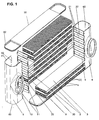
- the items such as flat tubes 1, ribs 4, tubesheets 5, 6 manifolds and side panels 30 are made of sheets, which, however, is not excluded that, for example, the flat tubes 1 could also be produced as drawn tubes.
- the flat tubes 1 have an approximately rectangular cross-section, but the narrow sides 2 can also be curved slightly outwards.
- internal inserts are in the flat tubes 1.
- the flat tubes 1 are then stacked with the ribs 4 to to form a flat tube ribbed block.
- the webs 22 are present.
- the webs 22 may be formed profiled to increase their rigidity.
- the side parts 30 are attached, which simultaneously close the frontal openings 60 of the collecting tanks 6 .
- the side parts 30 each have at their ends a cup-shaped reshaped closure piece which fits into the opening 60 into it.
- deformable holding elements 61 which engage in a slot 62 of the side parts, the side parts 30 are pre-fixed and hold the individual parts of the heat exchanger together.
- the heat exchanger is substantially prepared to carry out the CAB brazing process. All connections are made in a single pass in a brazing furnace.
- the shape of the projections 11 is suitably adapted to the existing in the narrow sides 2 contour of the flat tubes 1 , so that both the insertion is facilitated as well as dense solder joints are provided. This also certain manufacturing tolerances are absorbed.
- the distance between the projections 11 at the edge of the manifolds 6 corresponds to the distance between the flat tubes 1 in the row or with the height of the arranged between the flat tubes 1 ribs 4.
- certain tolerances must be allowed, however, by the appropriate shape of the projections 11th can be compensated.
- the headers 6 are particularly easy to manufacture, simple shape. Only two folds are necessary to form the two longitudinal walls and a transverse wall. For example, connecting pieces 70 can be easily realized by forming processes.
- tube sheets 5 are used, which are made of endless tape and only need to be cut to the appropriate length, because they have no bevelled edges on their faces. There are therefore no expensive drawing tools needed.
- Figs. 4 and 5 There it can be seen that at the edge 10 of the collecting tank 6 with the projections 11 comparable approach 100 is present. This cooperates with the corresponding cutout 101 on the edge 20 of the tube plate 5 and ensures there dense solder joints. It can also be seen from FIG. 5 that the openings 21 in the tubesheet 5 extend into the rim 20 , which is indicated by the reference numeral 22 .
- the tubesheets 5 during assembly can also be pushed transversely to their longitudinal direction, or in the direction of the broad sides 3 of the flat tube ends, onto the same. In the prior art, this requires a movement in the longitudinal direction of the flat tubes. There is talk of "pulling up" the tubesheets.
- FIGS. 3 and 6 show, in a view of one of the side parts 30, that there are no lateral projections of the tubesheets 5 over the flat tube ribs block.
- the width of the side parts 30 corresponds approximately to the extent of the broad sides 3 of the flat tubes . 1
- the heat exchanger according to the invention allows a fairly easy access from the outside to soldering critical connections.
- Such critical connections are the flat tube tube sheet connections. If there are any leaks after the soldering process has been carried out, the corresponding points can be simply aftertreated and eliminated in a second soldering pass as they are largely accessible. In heat exchangers of the prior art, such a thing is often not possible, which is expressed by high reject rates.
- Fig. 7 shows schematically a single flat tube 1, namely a view of the flat tube end.
- Such flat tubes 1 are present in the desired number of heat exchangers.
- two projections extend 11.
- the penetration depth needs to be only a few millimeters, 10 - 15 mm is already more than enough. Practically it will be less.
- the one projection 11 is located at one edge of the collecting tank 6 and the other projection 11 at the opposite other edge 10 of the Collection box 6.
- the projections 11 are close to the narrow sides 2 of the flat tube 1 from the inside.
- an inner insert 80 as is typical in particular for charged with cooling air charge air cooler. In other applications, an indoor use is completely dispensed with.
- the projections 11 have a favorable effect on the reduction of the harmful bypass, which comes into play as a further advantage of the invention.
- the small gaps in the corners of the flat tube 1 have their cause in the representation. In practice, they are not available or are securely closed during the soldering process. The mentioned gaps will also level when inserting the projections 11 , because the projections 11 hold both broad sides 3 in the direction of the arrow under a certain tension.
- FIGS. 8 and 9 now show an alternative design, in which the projections 11 are arranged on the tubesheets 5 .
- the tubesheets 5 must be mounted in the tube longitudinal direction, at the same time the projections 11 are inserted into the flat tube ends 1 . Thereafter, the headers 6 and the side members 30 are attached and mounted.
- the invention accordingly provides an innovative product which, compared to the state of the art, leaves only little to be desired.
Landscapes
- Engineering & Computer Science (AREA)
- Mechanical Engineering (AREA)
- Physics & Mathematics (AREA)
- Thermal Sciences (AREA)
- General Engineering & Computer Science (AREA)
- Heat-Exchange Devices With Radiators And Conduit Assemblies (AREA)
- Details Of Heat-Exchange And Heat-Transfer (AREA)
Priority Applications (9)
| Application Number | Priority Date | Filing Date | Title |
|---|---|---|---|
| EP05012589A EP1731864A1 (fr) | 2005-06-11 | 2005-06-11 | Echangeur de chaleur métallique et procédé de fabrication de celui-ci |
| CNA2006800207763A CN101194140A (zh) | 2005-06-11 | 2006-02-18 | 全金属换热器及其制造方法 |
| US11/916,459 US20080230213A1 (en) | 2005-06-11 | 2006-02-18 | Fully-Metal Heat Exchanger And Method For Its Production |
| EP06707072A EP1774245B1 (fr) | 2005-06-11 | 2006-02-18 | Echangeur thermique integralement metallique et procede de fabrication associe |
| KR1020087000720A KR100957665B1 (ko) | 2005-06-11 | 2006-02-18 | 풀-메탈 열 교환기 및 이의 제조 방법 |
| ES06707072T ES2302323T3 (es) | 2005-06-11 | 2006-02-18 | Intercambiadores de calor enteramente metalico y procedimiento para su fabricacion. |
| BRPI0611998-0A BRPI0611998A2 (pt) | 2005-06-11 | 2006-02-18 | trocador de calor integralmente de metal e método para sua produção |
| PCT/EP2006/001487 WO2006133748A1 (fr) | 2005-06-11 | 2006-02-18 | Echangeur thermique integralement metallique et procede de fabrication associe |
| DE502006000358T DE502006000358D1 (de) | 2005-06-11 | 2006-02-18 | Ganz-metall-wärmetauscher und verfahren zu seiner herstellung |
Applications Claiming Priority (1)
| Application Number | Priority Date | Filing Date | Title |
|---|---|---|---|
| EP05012589A EP1731864A1 (fr) | 2005-06-11 | 2005-06-11 | Echangeur de chaleur métallique et procédé de fabrication de celui-ci |
Publications (1)
| Publication Number | Publication Date |
|---|---|
| EP1731864A1 true EP1731864A1 (fr) | 2006-12-13 |
Family
ID=35124736
Family Applications (1)
| Application Number | Title | Priority Date | Filing Date |
|---|---|---|---|
| EP05012589A Withdrawn EP1731864A1 (fr) | 2005-06-11 | 2005-06-11 | Echangeur de chaleur métallique et procédé de fabrication de celui-ci |
Country Status (2)
| Country | Link |
|---|---|
| EP (1) | EP1731864A1 (fr) |
| CN (1) | CN101194140A (fr) |
Cited By (5)
| Publication number | Priority date | Publication date | Assignee | Title |
|---|---|---|---|---|
| CN103105091A (zh) * | 2013-02-20 | 2013-05-15 | 安徽天祥空调科技有限公司 | 用于整体钎焊全铝质模块散热器的边板 |
| CN109405302A (zh) * | 2018-11-30 | 2019-03-01 | 浙江华地电子有限公司 | 一种不锈钢换热器水盒子 |
| CN112577334A (zh) * | 2019-09-27 | 2021-03-30 | 浙江盾安热工科技有限公司 | 换热器 |
| DE102021213357A1 (de) | 2021-11-26 | 2023-06-01 | Robert Bosch Gesellschaft mit beschränkter Haftung | Kühlvorrichtung zur Kühlung von elektronischen Bauteilen |
| WO2024139389A1 (fr) * | 2022-12-30 | 2024-07-04 | 华为技术有限公司 | Condenseur et système de dissipation de chaleur |
Families Citing this family (6)
| Publication number | Priority date | Publication date | Assignee | Title |
|---|---|---|---|---|
| US9309839B2 (en) | 2010-03-18 | 2016-04-12 | Modine Manufacturing Company | Heat exchanger and method of manufacturing the same |
| AU2011201083B2 (en) * | 2010-03-18 | 2013-12-05 | Modine Manufacturing Company | Heat exchanger and method of manufacturing the same |
| CN102996230A (zh) * | 2012-11-19 | 2013-03-27 | 泰安鼎鑫冷却器有限公司 | 用于中冷器的冷却管加强卡 |
| CN106802099B (zh) * | 2015-11-25 | 2020-09-29 | 浙江三花汽车零部件有限公司 | 一种换热器 |
| CN110887393A (zh) * | 2018-09-07 | 2020-03-17 | 浙江盾安热工科技有限公司 | 扁管及换热器 |
| CN110514029A (zh) * | 2019-09-02 | 2019-11-29 | 枣庄学院 | 一种增压空气冷却器 |
Citations (5)
| Publication number | Priority date | Publication date | Assignee | Title |
|---|---|---|---|---|
| EP0656517A1 (fr) * | 1993-12-03 | 1995-06-07 | THERMAL-WERKE Wärme-, Kälte-, Klimatechnik GmbH | Echangeur de chaleur eau-air en aluminium pour véhicules automobiles |
| EP0704666A1 (fr) * | 1994-09-29 | 1996-04-03 | Zexel Corporation | Echangeur de chaleur |
| DE19819247A1 (de) * | 1998-04-29 | 1999-11-11 | Valeo Klimatech Gmbh & Co Kg | Wärmetauscher für Kraftfahrzeuge, insbesondere Wasser/Luft-Wärmetauscher oder Verdampfer |
| DE19942458A1 (de) * | 1998-09-29 | 2000-03-30 | Denso Corp | Wärmetauscher für eine Fahrzeug-Klimaanlage |
| DE10244629A1 (de) * | 2001-09-27 | 2003-04-10 | Denso Corp | Wärmetauscher mit stufenförmigem Behälter |
-
2005
- 2005-06-11 EP EP05012589A patent/EP1731864A1/fr not_active Withdrawn
-
2006
- 2006-02-18 CN CNA2006800207763A patent/CN101194140A/zh active Pending
Patent Citations (5)
| Publication number | Priority date | Publication date | Assignee | Title |
|---|---|---|---|---|
| EP0656517A1 (fr) * | 1993-12-03 | 1995-06-07 | THERMAL-WERKE Wärme-, Kälte-, Klimatechnik GmbH | Echangeur de chaleur eau-air en aluminium pour véhicules automobiles |
| EP0704666A1 (fr) * | 1994-09-29 | 1996-04-03 | Zexel Corporation | Echangeur de chaleur |
| DE19819247A1 (de) * | 1998-04-29 | 1999-11-11 | Valeo Klimatech Gmbh & Co Kg | Wärmetauscher für Kraftfahrzeuge, insbesondere Wasser/Luft-Wärmetauscher oder Verdampfer |
| DE19942458A1 (de) * | 1998-09-29 | 2000-03-30 | Denso Corp | Wärmetauscher für eine Fahrzeug-Klimaanlage |
| DE10244629A1 (de) * | 2001-09-27 | 2003-04-10 | Denso Corp | Wärmetauscher mit stufenförmigem Behälter |
Cited By (6)
| Publication number | Priority date | Publication date | Assignee | Title |
|---|---|---|---|---|
| CN103105091A (zh) * | 2013-02-20 | 2013-05-15 | 安徽天祥空调科技有限公司 | 用于整体钎焊全铝质模块散热器的边板 |
| CN109405302A (zh) * | 2018-11-30 | 2019-03-01 | 浙江华地电子有限公司 | 一种不锈钢换热器水盒子 |
| CN112577334A (zh) * | 2019-09-27 | 2021-03-30 | 浙江盾安热工科技有限公司 | 换热器 |
| CN112577334B (zh) * | 2019-09-27 | 2025-07-18 | 浙江盾安热工科技有限公司 | 换热器 |
| DE102021213357A1 (de) | 2021-11-26 | 2023-06-01 | Robert Bosch Gesellschaft mit beschränkter Haftung | Kühlvorrichtung zur Kühlung von elektronischen Bauteilen |
| WO2024139389A1 (fr) * | 2022-12-30 | 2024-07-04 | 华为技术有限公司 | Condenseur et système de dissipation de chaleur |
Also Published As
| Publication number | Publication date |
|---|---|
| CN101194140A (zh) | 2008-06-04 |
Similar Documents
| Publication | Publication Date | Title |
|---|---|---|
| EP0519334B1 (fr) | Echangeur de chaleur à tubes plats, procédé pour sa fabrication, applications et tubes plats pour échangeur de chaleur | |
| EP1281923B1 (fr) | Tube plat pour échangeur de chaleur et procédé de fabrication | |
| EP1774245B1 (fr) | Echangeur thermique integralement metallique et procede de fabrication associe | |
| EP0656517B1 (fr) | Echangeur de chaleur eau-air en aluminium pour véhicules automobiles | |
| DE102014005149B4 (de) | Gelöteter Wärmetauscher | |
| EP0864838B1 (fr) | Echangeur de chaleur pour véhicule automobile | |
| EP1701125A2 (fr) | Echangeur de chaleur à tubes plats et tube plat pour échangeur de chaleur | |
| EP2021717B1 (fr) | Échangeur thermique pour vehicules automobiles | |
| DE4305060C2 (de) | Gelöteter Wärmetauscher, insbesondere Verdampfer | |
| DE10219867A1 (de) | Wärmetauscher, insbesondere Ladeluftkühler | |
| DE19722098B4 (de) | Wärmeübertrager für ein Kraftfahrzeug | |
| EP1710526B1 (fr) | Échangeur de chaleur, notament refroidisseur d'air de suralimentation | |
| EP1273864A2 (fr) | Echangeur de chaleur | |
| EP1657512B1 (fr) | Echangeur de chaleur avec un profilé ouvert en tant que boîtier | |
| EP1376043B1 (fr) | Echangeur de chaleur avec diffuseur | |
| DE3834822A1 (de) | Waermetauscher | |
| EP1731864A1 (fr) | Echangeur de chaleur métallique et procédé de fabrication de celui-ci | |
| EP1567819A1 (fr) | Unite de transfert de chaleur, destinee en particulier a un vehicule automobile, et procede de production | |
| DE102017214822A1 (de) | Wärmeübertrager | |
| DE102008036614A1 (de) | Wärmetauscher | |
| DE102010040983A1 (de) | Gaskühler | |
| DE8801411U1 (de) | Wärmetauscher, insbesondere Wasser/Luft-Kühler aus Aluminium | |
| EP1148312B1 (fr) | Radiateur de véhicules | |
| DE102009012509A1 (de) | Wärmetauscher | |
| EP2167895B1 (fr) | Échangeur de chaleur |
Legal Events
| Date | Code | Title | Description |
|---|---|---|---|
| PUAI | Public reference made under article 153(3) epc to a published international application that has entered the european phase |
Free format text: ORIGINAL CODE: 0009012 |
|
| AK | Designated contracting states |
Kind code of ref document: A1 Designated state(s): AT BE BG CH CY CZ DE DK EE ES FI FR GB GR HU IE IS IT LI LT LU MC NL PL PT RO SE SI SK TR |
|
| AX | Request for extension of the european patent |
Extension state: AL BA HR LV MK YU |
|
| STAA | Information on the status of an ep patent application or granted ep patent |
Free format text: STATUS: THE APPLICATION HAS BEEN WITHDRAWN |
|
| 17P | Request for examination filed |
Effective date: 20070613 |
|
| 18W | Application withdrawn |
Effective date: 20070622 |