EP1733883A2 - Tête d'éjection de liquide et dispositif d'enregistrement - Google Patents
Tête d'éjection de liquide et dispositif d'enregistrement Download PDFInfo
- Publication number
- EP1733883A2 EP1733883A2 EP06115463A EP06115463A EP1733883A2 EP 1733883 A2 EP1733883 A2 EP 1733883A2 EP 06115463 A EP06115463 A EP 06115463A EP 06115463 A EP06115463 A EP 06115463A EP 1733883 A2 EP1733883 A2 EP 1733883A2
- Authority
- EP
- European Patent Office
- Prior art keywords
- vibration plate
- liquid chamber
- discharge head
- liquid
- liquid discharge
- Prior art date
- Legal status (The legal status is an assumption and is not a legal conclusion. Google has not performed a legal analysis and makes no representation as to the accuracy of the status listed.)
- Granted
Links
- 239000007788 liquid Substances 0.000 title claims abstract description 236
- 238000007599 discharging Methods 0.000 claims abstract description 36
- 238000005452 bending Methods 0.000 claims abstract description 33
- 239000010408 film Substances 0.000 claims description 16
- 239000000463 material Substances 0.000 claims description 10
- 239000010409 thin film Substances 0.000 claims description 4
- 238000006073 displacement reaction Methods 0.000 description 50
- 230000000052 comparative effect Effects 0.000 description 35
- 238000000034 method Methods 0.000 description 28
- XUIMIQQOPSSXEZ-UHFFFAOYSA-N Silicon Chemical compound [Si] XUIMIQQOPSSXEZ-UHFFFAOYSA-N 0.000 description 25
- 229910052710 silicon Inorganic materials 0.000 description 25
- 239000010703 silicon Substances 0.000 description 25
- 238000005530 etching Methods 0.000 description 22
- 239000000976 ink Substances 0.000 description 21
- 239000000758 substrate Substances 0.000 description 15
- 238000005498 polishing Methods 0.000 description 12
- 238000004891 communication Methods 0.000 description 9
- 239000011521 glass Substances 0.000 description 9
- 238000009616 inductively coupled plasma Methods 0.000 description 9
- 241000511976 Hoya Species 0.000 description 7
- 230000001965 increasing effect Effects 0.000 description 7
- 238000000059 patterning Methods 0.000 description 7
- KRHYYFGTRYWZRS-UHFFFAOYSA-N Fluorane Chemical compound F KRHYYFGTRYWZRS-UHFFFAOYSA-N 0.000 description 6
- 238000004519 manufacturing process Methods 0.000 description 6
- 229920002120 photoresistant polymer Polymers 0.000 description 6
- 230000002093 peripheral effect Effects 0.000 description 5
- 230000000694 effects Effects 0.000 description 4
- 239000003086 colorant Substances 0.000 description 3
- 238000000206 photolithography Methods 0.000 description 3
- 238000004080 punching Methods 0.000 description 3
- 238000000638 solvent extraction Methods 0.000 description 3
- 230000002708 enhancing effect Effects 0.000 description 2
- 239000004744 fabric Substances 0.000 description 2
- 238000005192 partition Methods 0.000 description 2
- 238000011084 recovery Methods 0.000 description 2
- 238000004544 sputter deposition Methods 0.000 description 2
- 238000002474 experimental method Methods 0.000 description 1
- 239000010985 leather Substances 0.000 description 1
- 230000010355 oscillation Effects 0.000 description 1
- 239000000123 paper Substances 0.000 description 1
- 238000007639 printing Methods 0.000 description 1
- 238000000790 scattering method Methods 0.000 description 1
- 239000007787 solid Substances 0.000 description 1
- 238000010998 test method Methods 0.000 description 1
- 230000007704 transition Effects 0.000 description 1
Images



Classifications
-
- B—PERFORMING OPERATIONS; TRANSPORTING
- B41—PRINTING; LINING MACHINES; TYPEWRITERS; STAMPS
- B41J—TYPEWRITERS; SELECTIVE PRINTING MECHANISMS, i.e. MECHANISMS PRINTING OTHERWISE THAN FROM A FORME; CORRECTION OF TYPOGRAPHICAL ERRORS
- B41J2/00—Typewriters or selective printing mechanisms characterised by the printing or marking process for which they are designed
- B41J2/005—Typewriters or selective printing mechanisms characterised by the printing or marking process for which they are designed characterised by bringing liquid or particles selectively into contact with a printing material
- B41J2/01—Ink jet
- B41J2/015—Ink jet characterised by the jet generation process
- B41J2/04—Ink jet characterised by the jet generation process generating single droplets or particles on demand
- B41J2/045—Ink jet characterised by the jet generation process generating single droplets or particles on demand by pressure, e.g. electromechanical transducers
-
- B—PERFORMING OPERATIONS; TRANSPORTING
- B41—PRINTING; LINING MACHINES; TYPEWRITERS; STAMPS
- B41J—TYPEWRITERS; SELECTIVE PRINTING MECHANISMS, i.e. MECHANISMS PRINTING OTHERWISE THAN FROM A FORME; CORRECTION OF TYPOGRAPHICAL ERRORS
- B41J2/00—Typewriters or selective printing mechanisms characterised by the printing or marking process for which they are designed
- B41J2/005—Typewriters or selective printing mechanisms characterised by the printing or marking process for which they are designed characterised by bringing liquid or particles selectively into contact with a printing material
- B41J2/01—Ink jet
- B41J2/135—Nozzles
- B41J2/14—Structure thereof only for on-demand ink jet heads
- B41J2/14201—Structure of print heads with piezoelectric elements
- B41J2/14233—Structure of print heads with piezoelectric elements of film type, deformed by bending and disposed on a diaphragm
-
- B—PERFORMING OPERATIONS; TRANSPORTING
- B41—PRINTING; LINING MACHINES; TYPEWRITERS; STAMPS
- B41J—TYPEWRITERS; SELECTIVE PRINTING MECHANISMS, i.e. MECHANISMS PRINTING OTHERWISE THAN FROM A FORME; CORRECTION OF TYPOGRAPHICAL ERRORS
- B41J11/00—Devices or arrangements of selective printing mechanisms, e.g. ink-jet printers or thermal printers, for supporting or handling copy material in sheet or web form
- B41J11/007—Conveyor belts or like feeding devices
Definitions
- the present invention relates to a liquid discharge head including a discharge port for discharging liquid droplets and a liquid chamber communicating to the discharge port, the liquid droplets being discharged by changing the volume of the liquid chamber; and a recording device.
- the liquid discharge head and the recording device of the present invention are applicable to a recording device for printing on paper, cloth, leather, nonwoven cloth, OHP sheet and the like, a patterning device, an application device and the like for applying liquid to a solid object such as a substrate, plate material and the like.
- recording devices such as an ink jet printers are widely used in the recording devices such as a printer, a facsimile and the like due to its low noise, low running cost, and easiness to miniaturize and colorize the device.
- the application of the liquid discharge head that uses piezoelectric actuator and the like as a patterning device dedicated for device manufacturing is becoming wider due to high degree of freedom of selection of the discharging liquid.
- the volume control for contracting or expanding the volume of the individual liquid chamber is performed by applying displacement that transition with time to a vibration plate configuring one part of an individual liquid chamber by providing an electrical signal.
- the liquid extends and starts to project out to the outer side in a liquid column state.
- the liquid flies over a gap or the recording gap (between liquid discharge head and material to be recorded) while being separated into a plurality of liquid droplets by surface tension.
- the object studies is the liquid discharge head referred to as a unimorph type (vendor type) piezo-recording head having a piezoelectric body and an electrode formed on the vibration plate.
- Various types with the thickness of the vibration plate changed were prepared in the piezo-recording head to compare the discharge life time.
- the criteria for determining the life time is the period during which liquid leakage is produced at the vibration plate portion due to breakage of the vibration plate. The number of discharging operations up to such point was evaluated. As can be easily assumed, the life time due to breakage of the vibration plate was shorter in the thinner the vibration plate.
- an actuator device in which the end of the lower electrode is the end of a piezoelectric body active part acting as a substantial drive portion of the piezoelectric element, and a film thickness part is arranged on the insulative layer on the outer side of the end of the lower electrode.
- a film thickness part is arranged on the insulative layer on the outer side of the end of the lower electrode.
- the present invention aims to provide a liquid discharge head with the width of the individual liquid chamber narrowed to realize high resolution, where the breakage of the vibration plate is prevented to extend the life time and ensure sufficient discharging life time; and a recording device.
- the liquid discharge head of the present invention comprises a discharge port for discharging liquid; a liquid chamber communicating to the discharge port; a piezoelectric element including one electrode layer, another electrode layer, and a piezoelectric film sandwiched between the one electrode layer and the other electrode layer independently arranged in correspondence to the liquid chamber, and including a piezoelectric drive portion at where the piezoelectric film deforms and displaces in correspondence to the liquid chamber; and a vibration plate interposed between the piezoelectric element and the liquid chamber, wherein a bending rigidity of both ends in an arranging direction of the one electrode layer of a portion corresponding to the piezoelectric drive portion of the vibration plate is greater than the bending rigidity of a region between both ends.
- the breakage of the vibration plate is prevented and the life time is extended by increasing the bending rigidity of a peripheral region of the vibration plate even if the vibration plate is thinned to sufficiently ensure displacement of the vibration plate.
- the liquid discharge head having high resolution and long life time is thereby provided.
- piezoelectric drive portion of a piezoelectric element in the present invention refers to a portion of the piezoelectric element corresponding to the self deforming portion sandwiched between a pair of electrode layers of the piezoelectric film, the portion of the piezoelectric element being displaceable in correspondence to the liquid chamber.
- the present invention has a feature in that the bending rigidity of both ends in the arrangement direction of one of the electrode layers of the portion corresponding to the piezoelectric drive portion of the vibration plate is greater than the bending rigidity of the region between both ends. In the present invention, the piezoelectric drive portion and the vibration plate being entirely contact with each other.
- Young's modulus of the portion corresponding to both ends of the vibration plate is greater than the Young's modulus of the region between both ends.
- the difference in the Young's modulus is preferably greater than or equal to 40GPa. This is because the effect of the present invention appears at a higher level.
- the portion corresponding to both ends of the vibration plate is thicker than the region between both ends.
- the difference in thickness is preferably greater than or equal to 1 ⁇ m. This is because the effect of the present invention appears at a higher level.
- a form in which the thick portion of both ends of the vibration plate bulges to the inner side of the liquid chamber is more preferable than a form in which the relevant thick portion bulges to the outer side. This is because the head is more easy to be manufactured (e.g., easy to grow film on the outer side of the vibration plate) when the bulged portion is on the inner side of the liquid chamber.
- the first exemplary embodiment is more preferable than the second exemplary embodiment. This is because the basic configuration of the first exemplary embodiment does not have the bulged portion at the vibration plate, thereby making the head easier to manufacture.
- the thickness of the vibration plate is preferably less than or equal to 10 ⁇ m. This is because the effect of the present invention appears at a higher level.
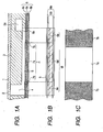
- the recording head functioning as the liquid discharge head includes a nozzle 2 functioning as a discharge port formed in a nozzle plate 1, and a communication port 4 and an individual liquid chamber 5 functioning as a liquid chamber formed in a base body 3 according to the present invention.
- a piezoelectric element 6 functioning as volume changing means is provided for pressurizing the ink or liquid in the individual liquid chamber 5 by controlling (changing) the volume of the individual liquid chamber 5. The pressurizing force by the piezoelectric element 6 is transmitted to the ink inside the individual liquid chamber 5 through the vibration plate 7.
- a first region (central region) 7a corresponding to the central part of the individual liquid chamber 5 inside the vibration plate 7 is made of heat resistance glass and the like having a small Young's modulus so as to obtain sufficient displacement of the vibration plate.
- a second region (peripheral region) 7b of the vibration plate 7 corresponding to the peripheral part of the individual liquid chamber 5 is made of silicon and the like. That is, the peripheral region or the second region 7b of the vibration plate 7 is configured to have a higher Young's modulus than the central region or the first region 7a on the inside.
- the vibration plate As miniaturization proceeds with smaller nozzle pitch of the liquid discharge head, the vibration plate must be thinned to obtain sufficient displacement of the vibration plate, which causes breakage at the vibration plate and shortens the life time of the liquid discharge head.
- the Young's modulus of the peripheral region of the vibration plate having a large displacement amount is increased to prevent the breakage of the vibration plate and to achieve longer life time of the liquid discharge head.
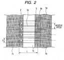
- FIGS. 1A, 1B, 1C and 2 illustrate example 1.
- a method of arranging the piezoelectric element 6 in correspondence with the nozzle 2, and discharging liquid droplets from the nozzle 2 by providing a drive signal corresponding to the recording information to the piezoelectric element 6 is adopted.
- the electrode wiring for supplying power to the piezoelectric element 6 is arranged.
- the piezoelectric element 6 includes an upper electrode (one electrode layer) 6b, a lower electrode (other electrode layer) 6c, and a piezoelectric film 6a sandwiched between a pair of electrodes.
- the vibration plate 7 and the lower electrode 6c are arranged on the entire surface of the substrate across the adjacent liquid chamber, and the piezoelectric film 6a and the upper electrode 6b are arranged corresponding individually to the liquid chamber 5 as shown in FIG. 1B (plan schematic view of FIG. 1A).
- the vibration plate 7 is arranged so as to be interposed between the piezoelectric element 6 and the liquid chamber 5.
- the reference numeral 5a is a supply path for supplying liquid to the liquid chamber 5.
- the supply path 5a is arranged extending in the direction perpendicular to the surface of FIG. 1A.
- the liquid is supplied to each of a plurality of liquid chambers 5 by way of the supply path 5b.
- the reference numeral 5 denotes the outer periphery of the liquid chamber.
- the reference numeral 6f is a piezoelectric drive portion where the piezoelectric film 6a deforms and displaces.
- the piezoelectric drive portion 6f of the piezoelectric element 6 refers to a portion corresponding to the self deforming portion sandwiched between the pair of electrodes 6b, 6c of the piezoelectric element 6, the portion (portion corresponding to the hatched portion in FIG. 1B) being displaceable in correspondence with the liquid chamber 5.
- the bending rigidity of both ends (correspond to 6e) in the arranging direction (left and right direction in FIG. 1B) of the upper electrode 6b of the portion corresponding to the piezoelectric drive portion 6f of the vibration plate 7 is greater than the bending rigidity of the region (correspond to 6d) between both ends.
- the base body 3 is manufactured in the following manner.
- An etching mask is formed on a silicon substrate using photolithography.
- An oxidized film and the like having a thickness of 1 ⁇ m is used for the etching mask.
- An ICP (Inductively Coupled Plasma) etching device is used for the etching device, and SF 6 , C 4 F 8 is used for the etching gas.
- the etching mask for forming a pattern of the individual liquid chamber 5 is arranged on the front surface of the silicon substrate having a thickness of 400 ⁇ m, and the individual liquid chamber 5 having a depth of 100 ⁇ m, width (D) of 100 ⁇ m, and length (L) of 2500 ⁇ m is formed, as shown in FIG. 2, using the ICP etching device.
- the individual liquid chamber 5 is partitioned by an individual liquid chamber partitioning wall 3a.
- the etching mask for forming a pattern of the communication port 4 is arranged on the back surface of the silicon substrate having a thickness of 400 ⁇ m.
- the communication port 4 having a depth of 300 ⁇ m is formed using the ICP etching device.
- vibration plate 7 is attached to the surface of the silicon substrate.
- the piezoelectric element 6 is then formed on the vibration plate 7, and the nozzle plate 1 separately processed through punching process and the like from the SUS plate etc. is attached to the back surface side of the silicon substrate.
- a method for manufacturing the vibration plate 7 is as described below. As shown in FIG. 1C, after bonding the (100) silicon substrate 7B having the Young's modulus of 130GPa and the heat resistance glass 7A of SD2 (anode bonding glass manufactured by HOYA) having the Young's modulus of 87GPa through anode bonding, polishing was performed for thinning, and the vibration plate 7 having a thickness of 3 ⁇ m was obtained.
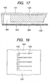
- the recording head as shown in FIGS. 17 and 18 was produced with nozzle (discharge port) density of 150dpi.
- the recording head includes a nozzle plate 1001 with nozzles 1002, a base body 1003 with a communication port 1004 and an individual liquid chamber 1005, a piezoelectric element 1006, and a vibration plate 1007.
- the width of the individual liquid chamber 1005 was about 100 ⁇ m
- the length of the individual liquid chamber 1005 was about 2500 ⁇ m
- the plate thickness of the vibration plate 1007 was about 3 ⁇ m.
- a rectangular voltage waveform was applied to the recording head, and liquid discharging operation was repeated. As a result, liquid leakage was observed at one part of the vibration plate 1007 around the 3 ⁇ 10 9th discharging operations.
- the recording head was produced with nozzle (discharge port) density of 150dpi, similar to comparative example 1.
- the width of the individual liquid chamber was about 100 ⁇ m
- the length of the individual liquid chamber was about 2500 ⁇ m
- the plate thickness of the vibration plate was about 5 ⁇ m.
- the rectangular voltage waveform was applied to the recording head, and liquid discharging operation is repeated. As a result, liquid leakage was observed at one part of the vibration plate around the 5 ⁇ 10 9th discharging operations.
- the recording head was produced with nozzle (discharge port) density of 150dpi, similar to comparative example 1.
- the width of the individual liquid chamber was about 100 ⁇ m
- the length of the individual liquid chamber was about 2500 ⁇ m
- the plate thickness of the vibration plate was about 7 ⁇ m.
- the rectangular voltage waveform was applied to the recording head, and liquid discharging operation was repeated. As a result, liquid leakage was observed at one part of the vibration plate around the 7 ⁇ 10 9th discharging operations.
- the time history data of the displacement of the surface of the vibration plate was taken using a non-contacting displacement gauge at a few points within 2500 ⁇ m in the longitudinal direction of the individual liquid chamber of comparative example 1 to grasp the displacement shape of the vibration plate. Since the thickness of the piezoelectric body and the electrode in the piezoelectric element is microscopic, the displacement of the surface of the piezoelectric element surface is assumed to be substantially the same as the displacement of the vibration plate.
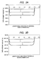
- FIG. 3A is a graph where the coordinate in the longitudinal direction of the individual liquid chamber is plotted in the horizontal axis, and the displacement amount is plotted in the vertical axis.
- the result of measuring the displacement of the surface of the vibration plate at the position of the central cross section of the individual liquid chamber at time t 1 , t 2 , t 3 of the period in which the individual liquid chamber expands is shown as graphs T 1 , T 2 , T 3 .
- the displacement of the vibration plate does not deform into a convex shape of one mountain, but deforms into two mountain shape having horns at both ends. Although there is difference in degree, such state was observed in all comparative examples 1 to 3.
- the portion of the horn at both ends receives a greater bend compared to other portions, and the bending state that is severe for the thin vibration plate is repeatedly added, whereby breakage is likely to occur.
- a method of suppressing the two mountains having horns formed at both ends in the longitudinal direction of the individual liquid chamber includes changing the material of the vibration plate to a material having a large Young's modulus. However, this method also reduces the displacement amount of the vibration plate of the central portion in the longitudinal direction of the individual liquid chamber, and a satisfactory discharge cannot be ensured.
- the vibration plate material having a large Young's modulus is used for the portion at both ends in the longitudinal direction of the individual liquid chamber, and the vibration plate material having a small Young's modulus is used for the central portion in the longitudinal direction of the individual liquid chamber in aim of suppressing the two mountains of horn shape produced at both ends in the longitudinal direction of the individual liquid chamber.
- the method for measuring the Young's modulus includes the known "film distortion method”, “pushing test method”, “Brillouin scattering method”, “ultrasonic microscopic method”, “resonance oscillation method”, “surface elastic wave method” and the like.
- the preferred range of the Young's modulus of the vibration plate will now be observed.
- the lower limit of the Young's modulus must be a value sufficient to flow (flow against weight of liquid) the "liquid present at a certain mass (or weight)" into the individual liquid chamber.
- the upper limit of the Young's modulus it is more suitable the larger the value for the purpose of preventing damage of the vibration plate.
- lowering of the displacement amount is improved by widening the width of the individual liquid chamber, and can be improved by further thinning the thickness of the vibration plate. Therefore, as long as the material is suitable for producing the recording head, the material having the largest Young's modulus that exists in the world can be used in the present embodiment.
- the experiment result of example 1 is as follows.
- the rectangular voltage waveform was applied to the recording head of example 1, and the liquid discharging operation was repeated.
- the life time enhanced compared to comparative example 1.
- the time history data of the displacement of the surface of the vibration plate was taken using the non-contacting displacement gauge at a few points within 2500 ⁇ m in the longitudinal direction of the individual liquid chamber.
- the two mountains of horn shape produced at both ends in the longitudinal direction of the individual liquid chamber, as shown in FIG. 3B, were suppressed, and thus severe bending state was not added as a consequence, and the life time is assumed to have extended.
- the (100) silicon substrate 27a having a thickness of 5 ⁇ m and the Young's modulus of 130GPa was considered as the base of the vibration plate 27.
- a thin film 27b of SiN (Young's modulus of 267GPa) was grown and stacked by sputtering and the like on the second region positioned on both ends of the first region contacting the liquid at the central part of the individual liquid chamber 5 of the silicon substrate 27a.
- the stacked configuration not only enhances bending rigidity by increasing the Young's modulus as a total, but also aims to enhance bending rigidity by increasing the thickness as a total.
- This vibration plate 27 was bonded with the base body 3 of silicon through anode bonding.
- the other producing methods are the same as comparative example 2.
- the rectangular voltage waveform was applied to the recording head and the liquid discharging operation was repeated.
- the life time enhanced compared to when the (100) silicon single body is made as the vibration plate of 5 ⁇ m.
- the time history data of the displacement of the surface of the vibration plate was taken using the non-contacting displacement gauge at a few points within 2500 ⁇ m in the longitudinal direction of the individual liquid chamber 5.
- the two mountains of horn shape produced at both ends in the longitudinal direction of the individual liquid chamber 5 were suppressed, and thus severe bending state was not added as a consequence, and the life time is assumed to have extended.
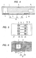
- the nozzle density is made to 80dpi (width of individual liquid chamber 5 is 270 ⁇ m), and the recording head including an individual liquid chamber 35 having a short length of 500 ⁇ m was produced in aim of greatly increasing the drive frequency.
- the end supporting distance is long in the longitudinal direction and the width direction (direction orthogonal to the arranging direction of one electrode layer) of the individual liquid chamber 35.
- deformation as shown in FIG. 3A was observed for both the longitudinal direction and the width direction of the individual liquid chamber 35.
- the vibration plate 37 including the first region 37a made of silicon and the second region 37b made of SD2 was produced by repeating bonding and polishing of (100) silicon or (111) silicon and SD2, and the recording head was produced.
- the second region 37b of the vibration plate 37 was formed by silicon, and the Young's modulus of which portion is relatively large.
- the rectangular voltage waveform was applied to the recording head and the liquid discharging operation was repeated. As a result, the life time enhanced compared to the recording head in which the vibration plate produced only with SD2. Further, the time history data of the displacement of the surface of the liquid chamber volume control means was taken using the non-contacting displacement gauge at a few points in the longitudinal direction and the width direction of the individual liquid chamber. As a result, as shown in FIG. 3B, the two mountains of horn shape produced at both ends in the longitudinal direction and the width direction of the individual liquid chamber were suppressed, and thus severe bending state was not added as a consequence, and the life time is assumed to have extended.
- the vibration plate was produced by the bonding technique and polishing, but may be produced with other techniques.
- the second region 47b having a large Young's modulus is concentrically arranged with respect to the first region 47a at the center.
- the liquid discharge head according to the present invention has the individual liquid chamber 5 or the liquid chamber formed in the base body 3 communicated to a plurality of discharge ports 2 formed in the nozzle plate 1 by way of the communication port 4.
- the piezoelectric element 6 is arranged in each individual liquid chamber 5, and the vibration plate 7 for conveying displacement by the piezoelectric element 6 to the liquid in the individual liquid chamber 5 is interposed between the piezoelectric element 6 and the individual liquid chamber 5.
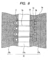
- the vibration plate 7 includes a thick thickness part 7d arranged in a region contacting the liquid in the individual liquid chamber 5, the region corresponding to both ends in the longitudinal direction of the individual liquid chamber 5; and a thin thickness part 7c arranged in a region contacting the liquid in the individual liquid chamber 5, the region corresponding to the central region of the individual liquid chamber 5.
- the thickness of the thick thickness part 7d is set to be thicker than the thin thickness part 7c to prevent breakage of the vibration plate 7.
- the present example illustrates the recording head serving as the liquid discharge head shown in FIGS. 9 and 10 produced by the method described below.
- the etching mask for patterning of the individual liquid chamber 5 made of oxidized film having a thickness of 1 ⁇ m is formed on the surface of the base body 3 of the silicon substrate and the like having a thickness of 400 ⁇ m through photolithography. Thereafter, the individual liquid chamber 5 partitioned by a partition wall 8 and having a depth of 100 ⁇ m is formed by the ICP (inductively Coupled Plasma) etching device using SF 6 , C 4 F 8 as the etching gas.
- ICP inductively Coupled Plasma
- the communication port 4 partitioned by the partitioning wall 8 and having a depth of 300 ⁇ m is formed using the ICP etching device.
- the vibration plate 7 is then attached to the surface of the base body 3 through anode bonding, and polishing is performed to obtain to a desired plate thickness.
- the vibration plate 7 is made of the anode bonding glass SD2 (manufactured by HOYA), and is produced through the method described below.
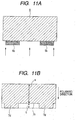
- etching is performed to a depth of 2 ⁇ m.
- Low concentration hydrofluoric acid solution was used as the etchant.
- the vibration plate 7 in which the thickness of the thick thickness part 7d is 5 ⁇ m and the thickness of the thin thickness part is 3 ⁇ m was obtained.
- the piezoelectric element 6 is formed on the vibration plate 7, and the nozzle plate 1 separately processed through punching process and the like from the SUS plate and the like is attached to the back surface of the base body 3.
- the rectangular voltage waveform was applied to the recording head according to the present example and the liquid discharge operation was repeated.
- the vibration plate 7 in which the thickness of the thick thickness part 7d of the vibration plate is 7 ⁇ m and the thickness of the thin thickness part 7c corresponding to the central region in the longitudinal direction of the individual liquid chamber 5 is 3 ⁇ m is obtained.
- Other steps are the same as example 9, and thus the explanation thereof is omitted.
- the rectangular voltage waveform was applied to the recording head according to the present example and the liquid discharge operation was repeated.
- etching was performed to a depth of 6 ⁇ m corresponding to the central region in the longitudinal direction of the vibration plate 7.
- Low concentration hydrofluoric acid solution was used as the etchant.
- the vibration plate 7 in which the thickness of the thick thickness part 7d of the vibration plate 7 is 9 ⁇ m and the thickness of the thin thickness part 7c is 3 ⁇ m was obtained.
- Other steps are the same as example 9, and thus the explanation thereof is omitted.
- the rectangular voltage waveform was applied to the recording head according to the present example and the liquid discharge operation was repeated.
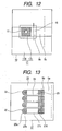
- the recording head having an extremely short individual liquid chamber 15 as shown in FIG. 12 was produced with a method similar to example 9 (80dpi).
- the individual liquid chamber 15 has a length of 500 ⁇ m and a width of 270 ⁇ m.
- deformation as shown in FIG. 3A was observed both in the longitudinal direction and the width direction of the individual liquid chamber 15.
- the vibration plate 17 of the present embodiment has a region contacting the liquid in the individual liquid chamber 15, which inner side region corresponding to the discharge port 12 configured by the thin thickness part 17c, and the outer side of the thin thickness part 17c is surrounded by the thick thickness part 17d.
- the thick thickness part 17d is made thicker than the thin thickness part 17c arranged on the inner side region corresponding to the discharge port 12.
- the rectangular voltage waveform was applied to the recording head according to the present example and the liquid discharge operation was repeated. As a result, the life time was extended compared to the recording head in which the vibration plate was produced at an even thickness.
- the result of taking the time history data of the displacement of the surface of the vibration plate using the non-contacting displacement gauge at a few points within 500 ⁇ m in the longitudinal direction and the width direction of the individual liquid chamber 15 was close to that shown in FIG. 3B. As shown in FIG. 3B, the two mountains of horn shape produced at the region corresponding to both ends in the longitudinal direction and the width direction of the individual liquid chamber 15 were suppressed, and thus severe bending state was not added as a consequence, and the life time is assumed to have extended.
- the recording head of the present comparative example is shown in FIGS. 17 and 18.
- the density of the discharge port (nozzle) 202 is 150dpi
- the width of the individual liquid chamber 205 is about 100 ⁇ m
- the length of the individual liquid chamber 205 is about 2500 ⁇ m
- the plate thickness of the vibration plate 207 is about 3 ⁇ m.
- the etching mask for patterning of the individual liquid chamber 205 is formed on the surface of the base body 203 of the silicon substrate and the like having a thickness of 400 ⁇ m through photolithography. Thereafter, the individual liquid chamber 205 partitioned by a partition wall 208 and having a depth of 100 ⁇ m is formed by the ICP etching device using SF 6 , C 4 F 8 as the etching gas.
- the communication port 204 partitioned by the partitioning wall 208 and having a depth of 300 ⁇ m is formed using the ICP etching device.
- the vibration plate 207 is then attached to the surface of the base body 203, and polishing is performed to obtain a desired plate thickness.
- the anode bonding glass SD2 (manufactured by HOYA) is used for the vibration plate 207.
- the volume changing means (piezoelectric element) 206 on the vibration plate 207 is formed, and the nozzle plate 201 separately processed through punching process and the like from the SUS plate and the like is attached to the back surface of the base body 203.
- the recording head according to the present comparative example is the same as comparative example 4 except for the fact that the plate thickness of the vibration plate 207 is about 5 ⁇ m.
- the recording head according to the present comparative example is the same as comparative example 4 except for the fact that the plate thickness of the vibration plate 207 is about 7 ⁇ m.
- the time history data of the displacement of the surface of the volume changing means was taken using a non-contacting displacement gauge at a few points within 2500 ⁇ m in the longitudinal direction of the individual liquid chamber to grasp the displacement shape of the vibration plate. Since the thickness of the piezoelectric body and the electrode in the volume changing means is microscopic, the displacement of the surface of the volume changing means is assumed to be substantially the same as the displacement of the vibration plate.
- the displacement of the surface of the volume changing means does not deform into a convex shape of one mountain, but deforms into two mountain shape having horns at both ends. Although there is difference in degree, such state was observed in all comparative examples 4 to 6.
- the portion of the horn at both ends receives a greater bend compared to other portions, and the bending state that is severe for the thin vibration plate is repeatedly added, whereby breakage is likely to occur.
- the present invention is also effective for the liquid discharge head in which the end 25a on the discharge port side of the individual liquid chamber 25 is an arc shaped liquid discharge head without horns.
- the thick thickness part 27d is formed in the region contacting the liquid in the individual liquid chamber 25 of the vibration plate 27, the region corresponding to both ends in the longitudinal direction of the individual liquid chamber according to the liquid discharge head of example 9 shown in FIGS. 9 and 10 described above.
- the thin thickness part 27c is arranged in the region contacting the liquid in the individual liquid chamber 25 of the vibration plate 27, the region corresponding to the central region in the longitudinal direction of the individual liquid chamber.
- the present invention is also effective for the liquid discharge head in which the region contacting the liquid in the individual liquid chamber of the vibration plate 37 is circular or substantially circular.
- the vibration plate 37 has the thick thickness part 37d concentrically surrounding the outer periphery of the thin thickness part 37c of the central region.
- the stacked configuration not only enhances bending rigidity by increasing The Young's modulus as a total, but also aims to enhance bending rigidity by increasing the thickness as a total. Therefore, the SiN that is grown and stacked is not limited to (100) silicon region, and may be positioned in a region across the (100) silicon and the SD2. This vibration plate was bonded to the base body of silicon through anode bonding. The other producing methods are the same as comparative example 2.
- the rectangular voltage waveform was applied to the recording head and the liquid discharging operation was repeated.
- the life time enhanced compared to when the (100) silicon single body is made as the vibration plate of 5 ⁇ m.
- the time history data of the displacement of the surface of the vibration plate was taken using the non-contacting displacement gauge at a few points within 2500 ⁇ m in the longitudinal direction of the individual liquid chamber.
- the two mountains of horn shape produced at both ends in the longitudinal direction of the individual liquid chamber 5 were suppressed, and thus severe bending state was not added as a consequence, and the life time is assumed to have extended.
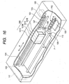
- FIG. 16 is a broken perspective view explaining the entire recording device mounted with the recording head.
- a medium to be recorded P fed to the device is conveyed to a recordable region of the recording head unit 100 by feeding rollers 109, 110 serving as medium conveying means.
- the recording head unit 100 is movably guided by two guide shafts 107, 102 along an extending direction (main scanning direction), and scans the recording region in a reciprocating manner.
- the scanning direction of the recording head unit 100 is the main scanning direction
- the conveying direction of the medium to be recorded P is the sub-scanning direction.
- the recording head for discharging ink droplets of a plurality of colors, and an ink tank 101 for supplying ink to each recording head are arranged in the recording head unit 100.
- the inks of a plurality of colors in the ink jet recording device of this example are four colors of black (Bk), cyan (C), magenta (M), and yellow (Y). The position of each color is in random order.
- a recovery system unit 112 is arranged at the lower part of the right end on the region where the recording head unit 100 is movable to perform recovery process on the discharge port of the recording head during the non-recording operation.
- the ink tanks for each color ink (Bk, C, M, Y) of black, cyan, magenta and yellow are all independently changeable.
- the recording head unit 100 is mounted with the recording head group for discharging Bk ink droplets, C ink droplets, M ink droplets, and Y ink droplets, Bk ink tank 101B, C ink tank 101C, M ink tank 101M, and Y ink tank 101Y.
- Each ink tank is connected to the recording head group, and supplies ink to the nozzle flow path communicating to the discharge port of the recording head group.
- the ink tank for each color may be integrally configured at an arbitrary combination.
- a liquid discharge head include a discharge port for discharging liquid; a liquid chamber communicating to the discharge port; a piezoelectric element including one electrode layer, another electrode layer, and a piezoelectric film sandwiched between the one electrode layer and the other electrode layer independently arranged in correspondence to the liquid chamber, and including a piezoelectric drive portion at where the piezoelectric film deforms and displaces in correspondence to the liquid chamber; and a vibration plate interposed between the piezoelectric element and the liquid chamber, wherein a bending rigidity of both ends in an arranging direction of the one electrode layer of a portion corresponding to the piezoelectric drive portion of the vibration plate is greater than the bending rigidity of a region between both ends.
Landscapes
- Particle Formation And Scattering Control In Inkjet Printers (AREA)
Applications Claiming Priority (2)
| Application Number | Priority Date | Filing Date | Title |
|---|---|---|---|
| JP2005175897 | 2005-06-16 | ||
| JP2005362597 | 2005-12-16 |
Publications (3)
| Publication Number | Publication Date |
|---|---|
| EP1733883A2 true EP1733883A2 (fr) | 2006-12-20 |
| EP1733883A3 EP1733883A3 (fr) | 2011-04-06 |
| EP1733883B1 EP1733883B1 (fr) | 2015-03-11 |
Family
ID=36956113
Family Applications (1)
| Application Number | Title | Priority Date | Filing Date |
|---|---|---|---|
| EP06115463.9A Not-in-force EP1733883B1 (fr) | 2005-06-16 | 2006-06-14 | Tête d'éjection de liquide et dispositif d'enregistrement |
Country Status (4)
| Country | Link |
|---|---|
| US (2) | US7625073B2 (fr) |
| EP (1) | EP1733883B1 (fr) |
| KR (1) | KR20060131660A (fr) |
| TW (1) | TWI295971B (fr) |
Cited By (2)
| Publication number | Priority date | Publication date | Assignee | Title |
|---|---|---|---|---|
| EP2990206A1 (fr) * | 2014-09-01 | 2016-03-02 | Seiko Epson Corporation | Tête d'éjection de liquide et appareil d'éjection de liquide |
| EP3409476A3 (fr) * | 2017-05-29 | 2019-02-13 | Seiko Epson Corporation | Dispositif piézoélectrique, tête de décharge de liquide et appareil de décharge de liquide |
Families Citing this family (7)
| Publication number | Priority date | Publication date | Assignee | Title |
|---|---|---|---|---|
| US8177142B2 (en) * | 2005-08-26 | 2012-05-15 | Ricciardi Jonathan J | Method and apparatus for an improved aerosol generator and associated uses and equipment |
| US8455271B2 (en) * | 2007-03-29 | 2013-06-04 | Xerox Corporation | Highly integrated wafer bonded MEMS devices with release-free membrane manufacture for high density print heads |
| JP5003549B2 (ja) * | 2007-03-30 | 2012-08-15 | ブラザー工業株式会社 | 液体移送装置及び液体移送装置の製造方法 |
| US9315021B2 (en) * | 2014-02-27 | 2016-04-19 | Xerox Corporation | Multiple thin film piezoelectric elements driving single jet ejection system |
| JP6631052B2 (ja) | 2015-07-02 | 2020-01-15 | セイコーエプソン株式会社 | 圧電デバイスの製造方法 |
| US11696507B2 (en) | 2018-12-14 | 2023-07-04 | Stmicroelectronics S.R.L. | Piezoelectric MEMS device with a suspended membrane having high mechanical shock resistance and manufacturing process thereof |
| JP7761423B2 (ja) * | 2021-08-20 | 2025-10-28 | 日本特殊陶業株式会社 | 超音波トランスデューサ |
Citations (2)
| Publication number | Priority date | Publication date | Assignee | Title |
|---|---|---|---|---|
| JP2000272126A (ja) | 1999-03-24 | 2000-10-03 | Seiko Epson Corp | アクチュエータ装置及びその製造方法並びにインクジェット式記録ヘッド及びインクジェット式記録装置 |
| JP3379538B2 (ja) | 1992-04-23 | 2003-02-24 | セイコーエプソン株式会社 | 液体噴射ヘッドおよび液体噴射記録装置 |
Family Cites Families (17)
| Publication number | Priority date | Publication date | Assignee | Title |
|---|---|---|---|---|
| JP2952994B2 (ja) | 1990-08-20 | 1999-09-27 | セイコーエプソン株式会社 | インクジェットヘッド |
| JP3379106B2 (ja) * | 1992-04-23 | 2003-02-17 | セイコーエプソン株式会社 | 液体噴射ヘッド |
| IT1268870B1 (it) * | 1993-08-23 | 1997-03-13 | Seiko Epson Corp | Testa di registrazione a getto d'inchiostro e procedimento per la sua fabbricazione. |
| WO1998018632A1 (fr) * | 1996-10-28 | 1998-05-07 | Seiko Epson Corporation | Tete d'enregistrement a jet d'encre |
| JP3610810B2 (ja) | 1998-02-18 | 2005-01-19 | セイコーエプソン株式会社 | インクジェット式記録ヘッド及びインクジェット式記録装置 |
| DE69924047T2 (de) * | 1998-04-28 | 2006-02-02 | Canon K.K. | Flüssigkeitsausstossverfahren |
| ATE303250T1 (de) * | 1998-06-08 | 2005-09-15 | Seiko Epson Corp | Tintenstrahlaufzeichnungskopf und tintenstrahlaufzeichnungsvorrichtung |
| JP3738804B2 (ja) | 1998-07-22 | 2006-01-25 | セイコーエプソン株式会社 | インクジェット式記録ヘッド及びインクジェット式記録装置 |
| DE69940298D1 (de) * | 1998-12-29 | 2009-03-05 | Canon Kk | Flüssigkeitsausstosskopf, Flüssigkeitsausstossverfahren und Flüssigkeitsausstossdruckgerät |
| JP2002059555A (ja) * | 2000-08-18 | 2002-02-26 | Seiko Epson Corp | インクジェット式記録ヘッド及びその製造方法並びにインクジェット式記録装置 |
| JP3491688B2 (ja) * | 2000-10-16 | 2004-01-26 | セイコーエプソン株式会社 | インクジェット式記録ヘッド |
| JP2002187271A (ja) | 2000-12-20 | 2002-07-02 | Seiko Epson Corp | インクジェット式記録ヘッド及びインクジェット式記録装置 |
| EP1199171A3 (fr) * | 2000-10-16 | 2003-04-09 | Seiko Epson Corporation | Tête d'enregistrement à jet d'encre à jet d'encre et appareil d'enregistrement à jet d'encre |
| JP3661775B2 (ja) * | 2001-02-14 | 2005-06-22 | セイコーエプソン株式会社 | インクジェット式記録ヘッドの製造方法 |
| JP3956964B2 (ja) * | 2003-09-25 | 2007-08-08 | ブラザー工業株式会社 | 液体移送装置及び圧電アクチュエータ |
| JP3820589B2 (ja) * | 2003-09-26 | 2006-09-13 | 富士写真フイルム株式会社 | 液体吐出ヘッドとその製造方法及びインクジェット記録装置 |
| JP3997485B2 (ja) * | 2003-09-26 | 2007-10-24 | ブラザー工業株式会社 | 液体移送装置 |
-
2006
- 2006-05-26 US US11/441,026 patent/US7625073B2/en not_active Expired - Fee Related
- 2006-06-02 TW TW095119712A patent/TWI295971B/zh active
- 2006-06-14 EP EP06115463.9A patent/EP1733883B1/fr not_active Not-in-force
- 2006-06-15 KR KR1020060053683A patent/KR20060131660A/ko not_active Ceased
-
2009
- 2009-04-28 US US12/431,274 patent/US8033653B2/en not_active Expired - Fee Related
Patent Citations (2)
| Publication number | Priority date | Publication date | Assignee | Title |
|---|---|---|---|---|
| JP3379538B2 (ja) | 1992-04-23 | 2003-02-24 | セイコーエプソン株式会社 | 液体噴射ヘッドおよび液体噴射記録装置 |
| JP2000272126A (ja) | 1999-03-24 | 2000-10-03 | Seiko Epson Corp | アクチュエータ装置及びその製造方法並びにインクジェット式記録ヘッド及びインクジェット式記録装置 |
Cited By (4)
| Publication number | Priority date | Publication date | Assignee | Title |
|---|---|---|---|---|
| EP2990206A1 (fr) * | 2014-09-01 | 2016-03-02 | Seiko Epson Corporation | Tête d'éjection de liquide et appareil d'éjection de liquide |
| US9346270B2 (en) | 2014-09-01 | 2016-05-24 | Seiko Epson Corporation | Liquid ejecting head and liquid ejecting apparatus |
| EP3409476A3 (fr) * | 2017-05-29 | 2019-02-13 | Seiko Epson Corporation | Dispositif piézoélectrique, tête de décharge de liquide et appareil de décharge de liquide |
| US10639893B2 (en) | 2017-05-29 | 2020-05-05 | Seiko Epson Corporation | Piezoelectric device, liquid discharging head, and liquid discharging apparatus |
Also Published As
| Publication number | Publication date |
|---|---|
| US20070002092A1 (en) | 2007-01-04 |
| US7625073B2 (en) | 2009-12-01 |
| TWI295971B (en) | 2008-04-21 |
| KR20060131660A (ko) | 2006-12-20 |
| TW200709946A (en) | 2007-03-16 |
| US20090213187A1 (en) | 2009-08-27 |
| EP1733883B1 (fr) | 2015-03-11 |
| US8033653B2 (en) | 2011-10-11 |
| EP1733883A3 (fr) | 2011-04-06 |
Similar Documents
| Publication | Publication Date | Title |
|---|---|---|
| US8033653B2 (en) | Liquid discharge head and recording device | |
| EP1170127B1 (fr) | Tête d'enregistrement par jet d'encre | |
| US20030020787A1 (en) | Ink Jet Head and ink Jet Type Recording Apparatus | |
| US7090340B2 (en) | Inkjet recording head and inkjet recording apparatus using the same | |
| US10618283B2 (en) | Piezoelectric device, liquid discharge head, and liquid discharge apparatus | |
| JP7331558B2 (ja) | 液体噴射ヘッド及び液体噴射装置 | |
| JP4032283B2 (ja) | マルチノズルインクジェットヘッド及びその製造方法 | |
| EP0950525A2 (fr) | Tête d'enregistrement à jet d'encre | |
| JPWO2001072520A1 (ja) | マルチノズルインクジェットヘッド及びその製造方法 | |
| CN100480049C (zh) | 液体排放头和记录装置 | |
| JP2008049569A (ja) | 液体移送装置及び液体移送装置の製造方法 | |
| JP2004160941A (ja) | 液滴噴射ヘッド、インクジェット記録装置 | |
| JP2001010040A (ja) | インクジェットヘッド | |
| JP2870462B2 (ja) | インクジェット記録ヘッド | |
| JP4829692B2 (ja) | 液体吐出ヘッドおよび記録装置 | |
| JP2010228276A (ja) | 液体噴射ヘッド及び液体噴射装置並びにアクチュエーター装置 | |
| JP2008055900A (ja) | 液滴噴射装置及び液滴噴射装置の製造方法 | |
| JP4639492B2 (ja) | インクジェット式記録ヘッド及びインクジェット式記録装置 | |
| JP2002248774A (ja) | インクジェット式記録ヘッド及びインクジェット式記録装置 | |
| JP2007062251A (ja) | 液体吐出ヘッド、液体吐出ヘッドの製造方法、記録液カートリッジ、画像形成装置 | |
| JP2003103778A (ja) | インクジェットヘッド及びその製造方法 | |
| JP2715969B2 (ja) | インクジェットプリントヘッド | |
| JPH11300958A (ja) | インクジェット式記録ヘッド | |
| JP2024142442A (ja) | 液体噴射ヘッド | |
| JP5568854B2 (ja) | 液体噴射ヘッド及び液体噴射装置 |
Legal Events
| Date | Code | Title | Description |
|---|---|---|---|
| PUAI | Public reference made under article 153(3) epc to a published international application that has entered the european phase |
Free format text: ORIGINAL CODE: 0009012 |
|
| AK | Designated contracting states |
Kind code of ref document: A2 Designated state(s): AT BE BG CH CY CZ DE DK EE ES FI FR GB GR HU IE IS IT LI LT LU LV MC NL PL PT RO SE SI SK TR |
|
| AX | Request for extension of the european patent |
Extension state: AL BA HR MK YU |
|
| PUAL | Search report despatched |
Free format text: ORIGINAL CODE: 0009013 |
|
| AK | Designated contracting states |
Kind code of ref document: A3 Designated state(s): AT BE BG CH CY CZ DE DK EE ES FI FR GB GR HU IE IS IT LI LT LU LV MC NL PL PT RO SE SI SK TR |
|
| AX | Request for extension of the european patent |
Extension state: AL BA HR MK RS |
|
| 17P | Request for examination filed |
Effective date: 20111006 |
|
| AKX | Designation fees paid |
Designated state(s): DE FR GB IT |
|
| 17Q | First examination report despatched |
Effective date: 20111208 |
|
| GRAP | Despatch of communication of intention to grant a patent |
Free format text: ORIGINAL CODE: EPIDOSNIGR1 |
|
| INTG | Intention to grant announced |
Effective date: 20140926 |
|
| RAP1 | Party data changed (applicant data changed or rights of an application transferred) |
Owner name: CANON KABUSHIKI KAISHA |
|
| GRAS | Grant fee paid |
Free format text: ORIGINAL CODE: EPIDOSNIGR3 |
|
| GRAA | (expected) grant |
Free format text: ORIGINAL CODE: 0009210 |
|
| AK | Designated contracting states |
Kind code of ref document: B1 Designated state(s): DE FR GB IT |
|
| REG | Reference to a national code |
Ref country code: GB Ref legal event code: FG4D |
|
| REG | Reference to a national code |
Ref country code: DE Ref legal event code: R096 Ref document number: 602006044751 Country of ref document: DE Effective date: 20150423 |
|
| PGFP | Annual fee paid to national office [announced via postgrant information from national office to epo] |
Ref country code: DE Payment date: 20150630 Year of fee payment: 10 |
|
| REG | Reference to a national code |
Ref country code: DE Ref legal event code: R097 Ref document number: 602006044751 Country of ref document: DE |
|
| PG25 | Lapsed in a contracting state [announced via postgrant information from national office to epo] |
Ref country code: IT Free format text: LAPSE BECAUSE OF FAILURE TO SUBMIT A TRANSLATION OF THE DESCRIPTION OR TO PAY THE FEE WITHIN THE PRESCRIBED TIME-LIMIT Effective date: 20150311 |
|
| PLBE | No opposition filed within time limit |
Free format text: ORIGINAL CODE: 0009261 |
|
| STAA | Information on the status of an ep patent application or granted ep patent |
Free format text: STATUS: NO OPPOSITION FILED WITHIN TIME LIMIT |
|
| 26N | No opposition filed |
Effective date: 20151214 |
|
| REG | Reference to a national code |
Ref country code: FR Ref legal event code: ST Effective date: 20160229 |
|
| PG25 | Lapsed in a contracting state [announced via postgrant information from national office to epo] |
Ref country code: FR Free format text: LAPSE BECAUSE OF NON-PAYMENT OF DUE FEES Effective date: 20150630 |
|
| PGFP | Annual fee paid to national office [announced via postgrant information from national office to epo] |
Ref country code: GB Payment date: 20160628 Year of fee payment: 11 |
|
| REG | Reference to a national code |
Ref country code: DE Ref legal event code: R119 Ref document number: 602006044751 Country of ref document: DE |
|
| PG25 | Lapsed in a contracting state [announced via postgrant information from national office to epo] |
Ref country code: DE Free format text: LAPSE BECAUSE OF NON-PAYMENT OF DUE FEES Effective date: 20170103 |
|
| GBPC | Gb: european patent ceased through non-payment of renewal fee |
Effective date: 20170614 |
|
| PG25 | Lapsed in a contracting state [announced via postgrant information from national office to epo] |
Ref country code: GB Free format text: LAPSE BECAUSE OF NON-PAYMENT OF DUE FEES Effective date: 20170614 |